Deflected Wake Interaction of Tandem Flapping Foils
Abstract
Symmetric flapping foils are known to produce deflected jets at high frequency-amplitude combinations even at a zero mean angle of attack. This reduces the frequency range of useful propulsive configurations without side force. In this study, we numerically analyse the interaction of these deflected jets for tandem flapping foils undergoing coupled heave to pitch motion in a two dimensional domain. The impact of the flapping Strouhal number, foil spacing and phasing on wake interaction is investigated. Our primary finding is that the back foil is capable of cancelling the wake deflection and mean side force of the front foil, even when located up to 5 chord lengths downstream. This is achieved by attracting the incoming dipoles and disturbing their cohesion within the limits of the back foil’s range of flapping motion. We also show that the impact on cycle averaged thrust varies from high augmentation to drag generation depending on the wake patterns downstream of the back foil. These findings provide new insights towards the design of biomimetic tandem propulsors, as they expand their working envelope and ability to rapidly increase or decrease the forward speed by manipulating the size of the shed vortices.
keywords
1 Introduction

Due to their prevalence within the airborne and aquatic wildlife, single flapping foils have caught the interest of scientists and engineers alike since the early twentieth century (Knoller 1909; Betz 1912). Moreover, tandem flapping configurations e.g. insect wings (Alexander 1984; Thomas et al. 2004), plesiosaur flippers (Muscutt et al. 2017a) etc. are shown to outperform single flappers under certain wake-to-wake interactions.
For a single flapping foil the onset of thrust generation is marked by a reverse street (see figure 1b) downstream of its trailing edge (T.E.) (Von Karman 1935), although a lag between the two conditions exist (Godoy-Diana et al. 2008; Bohl & Koochesfahani 2009; Lagopoulos et al. 2019). This wake pattern is determined by the oscillating T.E. amplitude and frequency of the motion, which form together an Strouhal number as described by Triantafyllou et al. 1991. An increasing leads to permanent deflection of the jet (see figure 1c) and thus side force generation even when both the camber and the mean angle of attack are zero (Godoy-Diana et al. 2009; Cleaver et al. 2012). This is the result of formation when shedding vortices become strong enough to attract each other and depart from the centreline (Godoy-Diana et al. 2009; Godoy-Diana et al. 2008). Although three dimensional effects compromise the coherence of these structures (Zurman-Nasution et al. 2020), the formation and subsequent deflection of the dipole maintains its quasi two dimensional nature (Couder & Basdevant 1986; Godoy-Diana et al. 2008).
To improve the propulsive performance of a flapping system, various researchers have proposed the use of multiple foil configurations. In particular, tandem flapping foils are shown to improve thrust generation via both numerically (Muscutt et al. 2017b; Broering & Lian 2012; Akhtar et al. 2007) and experimentally (Muscutt et al. 2017a; Warkentin & DeLaurier 2007; Usherwood & Lehmann 2008). More specifically, thrust and efficiency augmentation can be achieved when the hind foil is weaving within the incoming vortices shed by the front one, determined by the inter foil spacing and phase lag.
A prominent feature of these studies is the relative lack of influence the downstream foil is said to have on the wake and forces of the upstream foil. However, those studies focus on cases with symmetric reverse streets where momentum exchange between shedding vortices is minimal. On the other hand, vortices of deflected wakes are often in very close proximity to each other, forming a long chain of well defined and correlated dipoles.
This paper focuses on the interaction between deflected wakes of tandem flapping foils undergoing harmonic motion. Simulations are conducted for single and tandem flapping configurations at a range of that ensures steady dipole formation. As the primary mechanism for wake deflection is two dimensional, we restrict ourselves to two-dimensional simulations in this work. It is revealed that certain phase-spacing combinations neutralise deflection for both foils. Distinct types of wake to wake interaction are observed and described in terms of their propulsive characteristics. In addition we clarify the mechanism of deflection cancellation and determine its limits in terms of a simple non-dimensional parameter, the spacing based Strouhal number.
2 Methodology
2.1 Geometry and kinematics
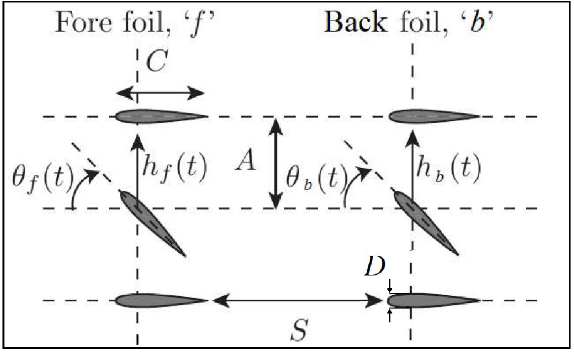
Figure 2 shows the basic elements of the simulated configuration. Two rigid NACA0016 with a thickness (where is the chord length) undergo sinusoidal heave to pitch coupling around the quarter chord, against a uniform free stream velocity . The pitching component of the motion is a sinusoidal rotation about the pivot point (normalised by the chord ) while the heaving part is a sinusoidal vertical translation with respect to the centreline. Since both motions are harmonic, coupling is simply achieved by the superposition of the two kinematic components:
| (1) |
where subscript refers to the single foil configuration while the subscripts and refer to the heaving and pitching component respectively.
The instantaneous angle of the foil due to pitching is expressed as the harmonic with the and being the amplitudes of pure heave and pure pitch respectively. In addition, the heave to pitch phase difference is set as = , which is shown to maximize the propulsive efficiency of the foil within the frequency range of interest (Platzer & Jones 2008).
Another important kinematic parameter in coupled motions is the effective angle of attack , which is the summation of the instantaneous pitch angle and the heave induced angle of attack. Thus for = the amplitude of is:
| (2) |
where is the amplitude of . Here, we set to achieve high efficiency kinematics (Muscutt et al. 2017b). Furthermore, the phase lag between the two foils is expressed as and will be referred to as simply the :
| (3) |
where subscripts and denote the front and back foils respectively.
2.2 Dimensionless parameters
Three aerodynamic parameters, scaled by , are used to describe the interaction between the flapping foil and the free stream (Koochesfahani 1989; Marais et al. 2012; Kim & Lee 2019). These are the Reynolds number (with being the kinematic viscosity), the Strouhal number, and the normalised peak-to-peak T.E. amplitude, defined as:
| (4) |
where is the cumulative T.E. amplitude of the coupled motion. Note that the use of in the definition of the above parameters enables us to retrieve the classic amplitude based Strouhal via the product . The latter can be understood as the ratio between the speed of the foil tip and (Godoy-Diana et al. 2008). To allow comparison with the results of Godoy-Diana et al. 2008, all simulations of this study are conducted for .
Another key parameter of a tandem configuration is the distance between the T.E. of the front foil and the L.E. of the back foil on the streamwise direction known as the inter foil (see figure 2). Therefore the chord normalised spacing is defined as:
| (5) |
The propulsive performance of the system is characterised by the thrust and lift coefficients. These are the x and y components of the force acting on the foil, normalised by the dynamic pressure:
| (6) |
Cycle averaged quantities are presented with an overbar to distinguish them from their instantaneous counterparts.
2.3 Computational method
The CFD solver utilized in this work is capable of simulating complex geometries and moving boundaries for a variety of Reynolds numbers in 2D and 3D domains, via the boundary data immersion method BDIM (Schlanderer et al. 2017). BDIM solves the viscous time-dependent Navier-Stokes equations and simulates the entire domain by combining the moving body and the ambient fluid through a kernel function. This technique has quadratic convergence and has been validated for flapping foil simulations over a wide span of kinematics (Maertens & Weymouth 2015; Polet et al. 2015).
The mesh profile is a rectangular Cartesian grid. A dense uniform grid is used near the body and in the near wake while an exponentially stretched mesh is used in the far-field. The boundary conditions consist of a uniform inflow, zero-gradient outflow and free-slip conditions on the upper and lower boundaries. Moreover, no slip conditions are imposed on the surface of the oscillating foil.
Mesh density is indicated by the number of grid points per chord. A grid convergence analysis was conducted to identify the appropriate resolution. As documented in Lagopoulos et al. 2019, a grid spacing of results in force predictions with less than error compared to a grid with twice the resolution in each direction and is therefore used for all simulations in this manuscript.
3 Results and discussion
3.1 Single foil analysis
Single foil arrangements undergoing harmonic heave to pitch coupling are tested for and in a two dimensional domain. is chosen so that across the entire range, ensuring steady wake deflection. Furthermore, the relatively high Strouhals guarantee that, all deflected wakes are thrust producing. The kinematic details and resulting are shown in table 1.

| 0.6250 | 1.405 | 0.59 | 0.400 | |||
| 0.9375 | 0.651 | 0.49 | 0.400 | |||
| 1.2500 | 0.437 | 0.42 | 0.400 | |||
| 1.5625 | 0.326 | 0.37 | 0.400 | |||
| 1.8750 | 0.258 | 0.32 | 0.390 | |||
| 2.1875 | 0.213 | 0.28 | 0.395 | |||
| 2.5000 | 0.181 | 0.33 | 0.405 |
The resultant wakes (see figure 3) maintain the basic features and deflection mechanism of asymmetric jets reported in literature for pure pitch (Godoy-Diana et al. 2009; Godoy-Diana et al. 2008; He et al. 2012) and pure heave (Cleaver et al. 2012; Kozłowski & Kudela 2014). Vortex circulation is proportional to the flapping frequency while the opposite is true for the distance between consecutive vortices. In the beginning, the first shed vortex follows an independent path away from the centreline. Yet, the distance between the second and the third subsequent vortices is noticeably smaller. This results in the formation of a dipole as shorter distances lead to stronger synergy among vortices according to the vortex induction law (Zheng & Wei 2012). The initial dipole departs from the centerline, breaking the symmetry of the mean jet and imposing its path to the subsequent dipole (Godoy-Diana et al. 2008).
3.2 Tandem foil analysis
Two dimensional tandem foils are tested for the kinematics and of the previous section. Simulations are performed for a wide range of spacings and in increments of , respectively. It is revealed that, at certain - combinations, the presence of the downstream foil results in a stable symmetric wake and zero net lift, even for the upstream foil. Specifically, we define lift cancellation as the condition when:
| (7) |
This condition is illustrated for two spacing at in figure 4. At and both curves are converging to zero, demonstrating complete lift cancellation on the front and back foil due to wake interaction. However, at , while at least two phases lead to , there is no phase which causes lift cancellation on both foils.


The manner in which the lift is cancelled depends on the interaction between the back foil and the incoming wake of the front foil. The specific type of interaction affects both the front and the back wake and has a crucial effect on the system‘s overall thrust (see table 2). In figure 5, three possible modes of lift cancellation are reported:
- •
Type I, where the back foil slides within the channel between the two vortices that form the incoming dipole (see figure 5a).
- •
Type II, where the back foil collides with one of the two vortical components of the dipole (see figure 5b).
- •
Type III, which is effectively an intermediate condition between the previous two modes as the aft foil partly collides with the outer region of the incoming vortex (see figure 5c).
Interestingly, figure 5a shows that at lift cancellation is still present even for a . In contrast, most published work supports the idea that downstream flow has no impact on the propulsive characteristics of the fore foil. These studies, however, focus on the interaction between non deflected jets where momentum exchange among subsequent vortices and the ambient fluid is minimal.
| Test Case | ||||||||
|---|---|---|---|---|---|---|---|---|
| Single Foil (Symmetric) | 0.2000 | 2.467 | - | - | 0.535 | - | 0.000 | - |
| Single Foil (Deflected) | 0.6250 | 1.405 | - | - | 0.590 | - | 0.400 | - |
| Tandem Foils (Classic) | 0.2000 | 2.467 | 5.0 | 0.535 | 0.910 | 0.002 | 0.014 | |
| Tandem Foils (Type I) | 0.6250 | 1.405 | 5.0 | 0.969 | 3.076 | -0.019 | 0.022 | |
| Tandem Foils (Classic) | 0.2000 | 2.467 | 2.0 | 0.535 | 0.909 | -0.017 | 0.033 | |
| Tandem Foils (Type II) | 0.6250 | 1.405 | 2.0 | 0.646 | -1.191 | 0.039 | -0.013 | |
| Tandem Foils (Classic) | 0.2000 | 2.467 | 1.0 | 0.535 | 0.828 | -0.003 | 0.010 | |
| Tandem Foils (Type III) | 1.5625 | 0.326 | 1.0 | 0.595 | 0.340 | 0.030 | 0.002 |
3.3 Thrust considerations
Thrust augmentation is a well reported phenomenon of in line flappers. When the back foil weaves between the incoming vortices, it experiences a higher compared to the front foil. This increases its thrust generation capacity and cases of have been observed (Muscutt et al. 2017b). Table 2 shows that Type I wake modes manage to exceed these values reaching up to . This should be expected since Type I occurs at a much higher compared to symmetric wake cases found in literature. Hence the circulation of the wake vortices experienced by the back foil is greater enabling the formation of similarly increased strength vortices by the foil and thereby a higher thrust augmentation.
Figure 6 shows the differences in the time averaged streamwise velocity between high performance conventional cases at and Type I modes at . Conventional test cases utilize the optimal combinations and derived from the work of Muscutt et al. 2017b while Type I wake modes are derived for and respectively. Clearly, the peak value of is much higher within Type I wakes due to the higher circulation of the vortices. Furthermore, the comparatively shorter distance between these vortices leads to a much narrower jet. Since , this condition enables the higher values of thrust reported above.

3.4 The physics of lift cancellation

The mechanism of lift cancellation is depicted in figure 7a. The initial dipole shed from the leading foil advects downstream and splits in to two after colliding with the vertically moving aft foil. Consequently, the advection speed of the clockwise vortex (red) decreases which reduces its distance from the subsequent dipole shed by the front foil. This affects the cohesion of the second dipole and its clockwise vortex (blue) is now under the influence of two counter-clockwise vortices. This situation propagates upstream, affecting every subsequent dipole in the same manner, resulting in wake convergence towards the centreline forming a classic reverse street.
As the collision of the first dipole with the rear foil is necessary for the lift cancellation, we need to examine the circumstances that would lead to this interception. By definition, a collision between two entities is only possible if their paths intersect. Assuming that the first dipole travels along an inclined downstream path set by the initial advection speed (see figure 7b), it can be shown that this path diverts from the freestream at an angle of (or ). This is based on assuming that the horizontal advection speed is proportional to the freestream speed () and the vertical advection speed is proportional to the vertical speed of the trailing edge of the front foil (). Note that the actual path of the dipole is not a straight line as it follows a more complex elliptic path. However, the factors leading to the overall angle are sufficient for this discussion. To achieve lift cancellation, this angle, , must be smaller than the largest angle between the trailing edge of the front foil and the L.E. of the back foil, so that:
| (8) |
This suggests that there is a Strouhal number that will act as a clear boundary between areas where lift cancellation is possible and areas where wake deflection is maintained. This geometric relationship accounts for all possible phase differences between the fore and aft foils and could even be independent of the frequency of the aft foil. This Strouhal number only depends on the ratio between the horizontal and vertical advection speeds of the dipole shed by the front foil which may vary with the kinematics of the front foil.
The number of lift cancellation instances are plotted on the map of figure 8 as a function of non-dimensional spacing () and non-dimensional frequency (). We observe that lift cancellation is impossible above a certain region marked with dashed solid black curve. This curve has the form . Fitting this equation to the data in figure 8 gives a Strouhal number that determines the lift cancellation border at . Taking into account 8 this means that . In other words, for a given spacing the back foil has the opportunity to impose wake symmetry only if its vertical speed is approximately less than (or equal to) a quarter of the horizontal advection speed of the first shed dipole.


A careful look at figure 8 reveals that the highest concentration of lift cancellations occurs at and . Once again this is linked to the development and propagation of the first permanent dipole. Figure 9 shows that at and the path of the dipole coincides with the centreline. In addition, the channel between its two vortices is approximately equal to the thickness of the back foil. This is an ideal condition, as it maximises the chances of collision with the dipole and thus the number of that lead to lift cancellation. Any increase in the changes the direction of the dipole and narrows the channel between its vortices, making it harder to dissolve by the back foil. On the other hand, a lower frequency leads to underdeveloped and more disoriented dipoles, minimizing the chances of impact. Consequently the amount of able to eliminate is reduced and with it, the amount of lift cancellation instances. This essentially describes a Goldilocks condition where the is the optimal combination for lift cancellation throughout the tested parameter space. i
4 Conclusions
Flapping foils, generating fully deflected wakes, are analysed in both single and tandem configurations undergoing coupled heave and pitch kinematics. We find that deflected wakes generated by foils undergoing coupled heave and pitch motion are similar to those reported for pure heave or pure pitch cases. Likewise, the driving mechanism of deflection is the development of dipole structures and their subsequent departure from the centreline.
Tandem configurations are able to reorder deflected jets into symmetric wakes with . Certain combinations are shown to direct both wakes back to the centreline even for inter foil distances of 5 chord lengths. To achieve lift cancellation the back foil has to dissolve the first shed dipole of the front wake and this is achieved when the angle between the T.E. of the front foil and the L.E. of the back is greater than the dipole’s convection angle. This can be expressed via a maximum , , above which any lift cancellation is impossible. Physically, this limit implies that the back foil must encounter the upstream wake within a few motion cycles for lift cancellation to be possible.
When the total lift of the tandem configuration is cancelled, the wake downstream becomes symmetric. Three wake modes are reported. Type I occurs when the back foil separates the two vortical components of the incoming dipole by weaving between them which leads to a remarkable increase in . Type II mode occurs when the L.E. directly collides on one of the dipole’s vortices which introduces a significant drag penalty. In addition, an intermediate mode Type III is reported whose behaviour varies according to the intensity of the vortex-foil collision.
This study is the first to provide evidence of the significant impact of the downstream field to the front foil. Furthermore, it is demonstrated that the wake deflection can be diminished with a subsequent remarkable thrust enhancement. These findings can support the design of high performance biomimetic propulsors, as a simple change of the back foil’s phase enables high thrust generation without side force at high frequencies previously considered impossible.
Acknowledgements
This research was supported financially by the Office of Naval Research award no. N62909-18-1-2091 and the Engineering and Physical Sciences Research Council doctoral training award (1789955). All data and post processing scripts supporting this study are openly available via the University of Southampton repository at https://doi.org/10.5258/SOTON/D1397.
References
- Akhtar et al. (2007) Akhtar, I., Mittal, R., Lauder, G. V. & Drucker, E. 2007 Hydrodynamics of a biologically inspired tandem flapping foil configuration. Theoretical and Computational Fluid Dynamics 21 (3), 155–170.
- Alexander (1984) Alexander, D. E. 1984 Unusual phase relationships between the forewings and hindwings in flying dragonflies. Journal of Experimental Biology 109 (1), 379–383.
- Betz (1912) Betz, A. 1912 Ein beitrag zur erklaerung segelfluges. Z Flugtech Motorluftschiffahrt 3, 269–272.
- Bohl & Koochesfahani (2009) Bohl, D.G. & Koochesfahani, M.M. 2009 MTV measurements of the vortical field in the wake of an airfoil oscillating at high reduced frequency. Journal of Fluid Mechanics 620, 63–88.
- Broering & Lian (2012) Broering, T. M. & Lian, Y.-S. 2012 The effect of phase angle and wing spacing on tandem flapping wings. Acta Mechanica Sinica 28 (6), 1557–1571.
- Cleaver et al. (2012) Cleaver, D.J., Wang, Z. & Gursul, I. 2012 Bifurcating flows of plunging aerofoils at high strouhal numbers. Journal of Fluid Mechanics 708, 349–376.
- Couder & Basdevant (1986) Couder, Y. & Basdevant, C. 1986 Experimental and numerical study of vortex couples in two-dimensional flows. Journal of Fluid Mechanics 173, 225–251.
- Godoy-Diana et al. (2008) Godoy-Diana, R., Aider, J.L. & Wesfreid, J.E. 2008 Transitions in the wake of a flapping foil. Physical Review E 77 (1), 016308.
- Godoy-Diana et al. (2009) Godoy-Diana, R., Marais, C., Aider, J.L. & Wesfreid, J.E. 2009 A model for the symmetry breaking of the reverse bénard–von kármán vortex street produced by a flapping foil. Journal of Fluid Mechanics 622, 23–32.
- He et al. (2012) He, G.-Y., Wang, Q., Zhang, X. & Zhang, S.-G. 2012 Numerical analysis on transitions and symmetry-breaking in the wake of a flapping foil. Acta Mechanica Sinica 28 (6), 1551–1556.
- Kim & Lee (2019) Kim, M. J. & Lee, J. H. 2019 Wake transitions of flexible foils in a viscous uniform flow. Physics of Fluids 31 (11), 111906.
- Knoller (1909) Knoller, R. 1909 Die gesetzedes luftwiderstandes. Flug-und Motortechnik (Wien) 3 (21), 1–7.
- Koochesfahani (1989) Koochesfahani, M.M. 1989 Vortical patterns in the wake of an oscillating airfoil. AIAA journal 27 (9), 1200–1205.
- Kozłowski & Kudela (2014) Kozłowski, T. & Kudela, H. 2014 Transitions in the vortex wake behind the plunging profile. Fluid Dynamics Research 46 (6), 061406.
- Lagopoulos et al. (2019) Lagopoulos, N. S., Weymouth, G. D. & Ganapathisubramani, B. 2019 Universal scaling law for drag-to-thrust wake transition in flapping foils. Journal of Fluid Mechanics 872.
- Maertens & Weymouth (2015) Maertens, A.P. & Weymouth, G.D. 2015 Accurate cartesian-grid simulations of near-body flows at intermediate reynolds numbers. Computer Methods in Applied Mechanics and Engineering 283, 106 – 129.
- Marais et al. (2012) Marais, C., Thiria, B., Wesfreid, J. E. & Godoy-Diana, R. 2012 Stabilizing effect of flexibility in the wake of a flapping foil. Journal of Fluid Mechanics 710, 659–669.
- Muscutt et al. (2017a) Muscutt, L. E., Dyke, G., Weymouth, G.l D., Naish, D., Palmer, C. & Ganapathisubramani, B. 2017a The four-flipper swimming method of plesiosaurs enabled efficient and effective locomotion. Proceedings of the Royal Society B: Biological Sciences 284 (1861), 20170951.
- Muscutt et al. (2017b) Muscutt, L. E., Weymouth, G. D. & Ganapathisubramani, B. 2017b Performance augmentation mechanism of in-line tandem flapping foils. Journal of Fluid Mechanics 827, 484–505.
- Platzer & Jones (2008) Platzer, M. & Jones, K. 2008 Flapping wing aerodynamics-progress and challenges. In 44th AIAA Aerospace Sciences Meeting and Exhibit, p. 500.
- Polet et al. (2015) Polet, D.T., Rival, D.E. & Weymouth, G.D. 2015 Unsteady dynamics of rapid perching manoeuvres. Journal of Fluid Mechanics 767, 323–341.
- Schlanderer et al. (2017) Schlanderer, S. C., Weymouth, G. D. & Sandberg, R. D. 2017 The boundary data immersion method for compressible flows with application to aeroacoustics. Journal of computational Physics 333, 440–461.
- Thomas et al. (2004) Thomas, A. L. R., Taylor, G. K., Srygley, R. B., Nudds, R. L. & Bomphrey, R. J. 2004 Dragonfly flight: free-flight and tethered flow visualizations reveal a diverse array of unsteady lift-generating mechanisms, controlled primarily via angle of attack. Journal of Experimental Biology 207 (24), 4299–4323.
- Triantafyllou et al. (1991) Triantafyllou, M.S., Triantafyllou, G.S. & Gopalkrishnan, R. 1991 Wake mechanics for thrust generation in oscillating foils. Physics of Fluids A: Fluid Dynamics 3 (12), 2835––2837.
- Usherwood & Lehmann (2008) Usherwood, J. R. & Lehmann, F.-O. 2008 Phasing of dragonfly wings can improve aerodynamic efficiency by removing swirl. Journal of The Royal Society Interface 5 (28), 1303–1307.
- Von Karman (1935) Von Karman, T. 1935 General aerodynamic theory-perfect fluids. Aerodynamic theory 2, 346–349.
- Warkentin & DeLaurier (2007) Warkentin, J. & DeLaurier, J. 2007 Experimental aerodynamic study of tandem flapping membrane wings. Journal of Aircraft 44 (5), 1653–1661.
- Zheng & Wei (2012) Zheng, Z. C. & Wei, Z. 2012 Study of mechanisms and factors that influence the formation of vortical wake of a heaving airfoil. Physics of Fluids 24 (10), 103601.
- Zurman-Nasution et al. (2020) Zurman-Nasution, A.N., Ganapathisubramani, B. & Weymouth, G.D. 2020 Influence of three-dimensionality on propulsive flapping. Journal of Fluid Mechanics 886.