Waveform-Domain NOMA: The Future of Multiple Access
Abstract
This paper introduces a novel noma (noma) concept named waveform-domain noma, which proposes the coexistence of different waveforms in the same re (re). Regarding the demands of each ues, appropriate waveforms are assigned intelligently and decoded at the receiver side properly. Since the performance gain of power-domain noma compared to mumimo (mumimo) degrades in the case of sic (sic) and channel estimation errors, noma is not considered as a work-item in 3GPP anymore. The novel waveform-domain noma concept provides a remedy for the problems of the power-domain noma scheme as well as flexibility in terms of reliability, latency, and energy efficiency. To mitigate sic errors, ldpc (ldpc) codes aided soft interference cancellation technique is used. As numerically evaluated, the proposed waveform-domain noma scheme outperforms the conventional power-domain noma in the power-balanced scenario.
Index Terms:
non-orthogonal multiple access, OFDM, OFDM-IM, power-domain NOMA, waveform-domain NOMAI Introduction
Over almost thirty years, tremendous efforts have been devoted to investigating new types of multiple access techniques based on the idea of serving multiple users at the same frequency, time, code, and spatial resources. Currently, these efforts are termed as noma, which has two different techniques, including power-domain and code-domain. The main motivation behind noma is the increased connectivity compared to oma (oma), which can meet the harsh requirements of the iot (iot) [1]. Besides studies, the concept of noma has included in various standardization efforts. A study for the application of noma in downlink transmission, named multi-user superposition transmission (MUST), was carried out for the 3rd Generation Partnership Project (3GPP) Release 14 [2]. A study for the application of noma for uplink transmission has been recently carried out for 3GPP Release 16, where different implementations of noma have been studied [3]. However, since power-domain noma has performance degradation in some cases mentioned throughout the paper, it is not considered as a work-item in Release 17.
Power-domain noma can yield much better spectral efficiency compared to oma unless channel gains of users are not similar [4]. To date, the literature on power-domain noma has based its work on perfect sic process [5], i.e., there is no residual error during the detection, reconstruction, and subtraction of the decoded user’s waveform from the superimposed received signal. However, this assumption is infeasible because the signal of the firstly decoded user should be estimated perfectly at the receiver [6]. Additionally, although the impact of channel estimation accuracy on the performance of bler (bler) is negligible for downlink noma [7], it should be considered for uplink noma regarding the reconstruction of firstly decoded user’s waveform. On the other hand, the transmit power of users is arranged in a way that the users’ power received at the bs (bs) is significantly different in order to enhance the overall system throughput in power-domain noma [8]. Since users transmitting at a similar power level may also be grouped in the case of high connectivity, various researches have been conducted to find new noma schemes that operate in power-balanced scenarios [9].
A novel uplink noma scheme with two users based on ofdm (ofdm) and ofdmim (ofdmim) is proposed in [10] where inherent power imbalance of ofdmim leads to better throughput compared to conventional ofdm and ofdm noma in the case of power-balanced scenario. However, the throughput performance of this scheme is not evaluated in the case of various power differences between the user’s received signal. Besides, noma with codeword-level sic is studied in [11] with turbo decoding to improve the reliability of the firstly decoded signal. However, in this study, the demodulated bits are reencoded and then subtracted from the superimposed received signal to perform demodulation for the second user. The catastrophic errors that would occur in the case of reencoding the falsely decoded bits are not considered.
This paper proposes a novel noma scheme called waveform-domain noma with transceiver design utilizing ldpc codes aided soft interference cancellation to improve bler performance through all received power level variations of users. The llr (llr) calculations are evaluated depending on the waveform type that is decoded first. The reconstruction of the firstly decoded user’s waveform is investigated with two different techniques in terms of evm (evm) as well as considering channel estimation errors. It is shown that the proposed waveform-domain noma scheme outperforms the conventional power-domain noma scheme in terms of bler performance in the power-balanced scenarios. Moreover, waveform-domain noma provides flexibility among users regarding their demands.
II System Model
For brevity, consider two users uplink noma scenario where both users transmit to a single bs over subcarriers in the presence of frequency selective channels, including awgn (awgn). Although the uplink scenario is considered, the waveform-domain noma concept is also applicable for downlink transmission.
II-A Conventional power-domain noma with ofdm+ofdm
Firstly, both ues encode their messages by ldpc codes and modulate via qam (qam), where data symbols of users are drawn from a complex symbol alphabet . Then, these symbols are ofdm modulated and transmitted to be received by the bs over the same re. Moreover, and denote the signal power of user 1 and user 2 for each subcarrier, respectively. In the ofdm with total subcarriers, the total powers of user 1 and user 2 become and , respectively. After the process of fft (fft) and removal of cyclic prefix, the baseband received signal at the th subcarrier is expressed as follows:
| (1) |
where , , , and are the channel gains and data symbols of users 1, and 2, respectively. Also, denotes the awgn at the th subcarrier.
Assuming that the signal of user 1 is decoded first, the capacity of user 1 () in conventional power-domain noma is given by
| (2) |
Assuming perfect sic, which is infeasible, the capacity of user 2 () is calculated as follows:
| (3) |
In the case of mlmud (mlmud) without sic, the decoding order does not have any effect on the sum-rate; therefore, any arbitrary decoding order can be assumed to be performed [12]. On the other hand, when ml (ml)- mud (mud) with sic is used, the stronger user should be decoded first.
II-B noma with ofdmim+ofdm
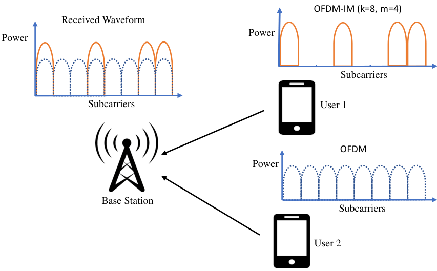
As Fig. 1 depicts, user 1 has utilized ofdmim waveform, whereas user 2 sends its signal via ofdm waveform over subcarriers. In the ofdmim scheme [13], the total bits are transmitted as follows: Firstly, subcarriers are split into subblocks consisting of subcarriers. The bits are used to determine the indices of active subcarriers where the total number of active subcarrier positions is denoted as . In each subblock , only out of subcarriers have activated. Activated subcarriers are used to map bits on to -ary signal constellation symbols selected from the complex set . The information of user 1 carried in the subblock is given by . As seen in Fig. 2a, the interleaved grouping is performed to increase the achievable rate of ofdmim [14]. In subblock , the vector of modulated symbols of user 2 carried with ofdm waveform is denoted by .
After fft and cyclic prefix removal, the superimposed received signal at the th subcarrier becomes
| (4) |
where . Moreover, denote as the received signal at the th subgroup. Fig. 2b depicts the reception process of the proposed noma scheme by decoding the ofdmim waveform first. However, the decoding may not always start with the ofdmim waveform. It depends on both power, subcarrier allocation, and modulation order.
III llr Calculations
This section includes the llr calculations of each user for two different noma schemes. Calculated llrs are sent to the ldpc decoder as input. For the sake of fair comparison, we have used the log-sum approximation technique [15] to calculate approximate llrs of two different noma schemes.
III-A llr calculations for noma with ofdm+ofdm
With ml-mud algorithm, the llr of the bit of user 1 at the th subcarrier, , is calculated as
| (5) | |||||
where denotes the set of all symbols whose label has in bit position . The complexity of this llr calculation, in terms of complex multiplications, becomes . After ldpc decoder fed with llrs, the symbols of user 1 is reconstructed and subtracted from the superimposed signal with inevitable sic error. The llrs of user 2 are calculated with the remaining signal and sent to the ldpc decoder in order to obtain bit decisions of user 2.
III-B llr calculations for noma with ofdmim+ofdm
The llr calculations for users’ bits in the ofdmim+ofdm noma scheme depend on which waveform is decided to be decoded first. As it is shown via numerical results in Section V, the total power level is not the unique limitation to decide which waveform should be decoded first. By decoding the ofdmim waveform first, the llr of the bit of user 1 at the th subgroup, is
| Λ_β^(i)^u_1 | (6) | ||||
| - min_u_1,β :u_1,β^(i)=0,u_2,β ∈{S}^k ∥ r β -h 1,β ⊙u 1,β -h 2,β ⊙u 2,β ∥ 2 σ 2 | |||||
where and denote the csi (csi) of users 1 and 2 through th subgroup, respectively, and denotes Hadamard multiplication. When the ofdmim waveform is decoded first, the complexity of llr calculation, in terms of complex multiplications, becomes . On the other hand, starting the decoding process with the ofdm waveform, the llr of the bit of user 2 at the th subcarrier, , becomes
| (7) | |||||
By decoding the ofdm waveform first, the complexity of llr calculation, in terms of complex multiplications, becomes . The waveform, whichever is decoded first, is reconstructed and subtracted from the aggregate received signal before the next user’s signal is decoded.
IV Waveform Domain noma
The waveform consisting of symbol, pulse shape, and lattice is the physical shape of the signal carrying modulated information [16]. The novel waveform-domain noma concept proposes the combination of different waveforms along with the non-orthogonal resources to introduce flexibility, separability, and detectability.
IV-A Waveform Selection
Some intelligent techniques for overlapping of users with different waveforms are studied in the prior works [17, 18, 19]. In [17], the separability aspect on the overlapping of two different waveforms, which are ofdm and cdma (cdma), is investigated with an iterative receiver design that is computationally complex. Similarly, the coexistence of ofdm and sc-fdma (sc-fdma) is studied in [18]. It is shown that the proposed mud approach utilizing iterative likelihood testing and sinr (sinr) based processing outperforms conventional sic. Moreover, the otfs (otfs) waveform is used for the high mobility user, whereas the signal of the low mobility user is transmitted via the ofdm waveform in [19]. This noma concept provides flexibility among users according to their mobility profiles. In our study, due to some superiority of ofdmim over ofdm such as ergodic achievable rate, papr (papr) reduction, and robustness to ici (ici) [20], ofdmim is chosen as a candidate for waveform-domain noma.
IV-B Reconstruction of the Waveform
In the uplink noma, errors in channel estimation and information detection propagate through the users coming in successive decoding order. To mitigate the performance degradation, we have used ldpc codes aided soft-interference cancellation. The soft reconstruction scheme is compared with the reencoding scheme proposed in [11] in terms of evm performance. evm is calculated as the ratio of rms (rms) power of the error vector to the rms power of the reference symbol overall ofdm subcarriers. For user 1, evm is calculated as follows:
| EVM(dB) |
where corresponds to the reconstructed symbol of user 1 at the th subcarrier. Two different techniques are used to reconstruct the decoded waveform to be stripped away from the superimposed received signal:
- 1.
If the signal of user 1 is demodulated first, the decoded bits of user 1 are reencoded and remodulated to reconstruct the waveform of user 1. Then it is subtracted from the superimposed signal to decode the signal of user 2.
- 2.
For the reconstruction of the firstly decoded signal, we have utilized the Gallager sum-product algorithm [21] that provides the total llr of each variable node at the stopping stage. The total llr shows how reliable the symbol consisting of the related bit can be reconstructed. Soft decision reconstruction is done at the end of the iterative process of the sum-product algorithm over the variable node as follows:
(8) where denotes the scale factor for the symbol consisting of the related bit and is the sum of the extrinsic llrs from connected check nodes and initial llr of the bit . For example, in BPSK modulation, the reconstructed signal of user 2 for the th bit on the th subcarrier becomes . Subsequently, the reconstructed signal is canceled from the aggregate received signal to decode the signal of another user.
Comparison of different reconstruction schemes is evaluated through Monte Carlo simulations over the Frequency Selective Channel with 10 taps. pdp (pdp) of the channel is considered as uniform. Moreover, mse (mse) is defined as the expected value of the normalized difference between the channel response and the channel estimation , , where denotes the expected value. In Fig. 3, evm results are provided for different mses in channel estimation. It portrays the superiority of the proposed reconstruction scheme with extrinsic soft llrs information obtained from the ldpc decoder. It can also be seen that, in the uplink noma, accuracy in channel estimation has a high impact on the reconstruction of the firstly decoded user’s waveform.
V Simulation Results and Discussion
The proposed technique is evaluated numerically through Monte Carlo simulations. As modulation order, QPSK signaling is used for both two noma schemes, where the equal data rate is satisfied with three active subcarriers in the group of four subcarriers (, ) for the user utilizing the ofdmim waveform. For ofdm+ofdm noma, the user with high received power is decoded first, then reconstructed, and canceled from the superimposed signal. On the other hand, for ofdmim+ofdm noma, decoding order is determined according to waveform type. Firstly decoded waveform is shown as bold for all given plots.
Fig. 4a and Fig. 4b demonstrate the uncoded performance of both noma schemes over the awgn channel for user 1 and user 2, respectively. The vertical axis denotes the required snr (snr) for a user to achieve the target bler of , whereas the horizontal axis denotes the power difference in terms of between two different users. ofdm+ofdm noma performance degrades significantly when users’ power is close to each other. As reference [10] shows that, ofdmim+ofdm noma is superior in terms of bler at the region, where power difference between users is very close to . This superiority comes from the inherent power difference of the ofdmim structure. However, as power imbalance between the users nears , the performance degrades significantly because power coefficients and in (4) equate the aggregate to the decision boundary. These regions are called as ambiguity region where user’s messages are not decoded even with high snr.
Fig. 5a, and Fig. 5b compare the ldpc coded conventional power-domain and the proposed waveform-domain noma with 0.5 code rate for users 1 and 2, respectively. The block length is chosen as 256. For waveform-domain noma, the decoding order should be chosen properly to enhance the performance gain. As opposed to conventional power-domain noma, the superior region of the user 1 and user 2 is roughly below and above , respectively. Using forward error correction with soft reconstruction and cancellation removes deep performance losses in the range of certain power differences for ofdmim+ofdm noma scheme. However, conventional power-domain noma still has a region where the performance degrades significantly. The proposed waveform-domain noma scheme is superior at the region where the power of users is close to each other without having significant performance losses as the power difference between users increases.
Fig. 6 depicts the bler performance of the conventional power-domain and the proposed waveform-domain noma schemes through frequency selective channel with 10 taps where users modulate their signal with equal power. Throughout the simulation, it is assumed that channel knowledge is present at the receiver. Since the channel is frequency selective, the received signal has different power imbalances over each subcarrier; in other words, power equality does not hold any more at the receiver side. Even in this case, better performance is obtained with the proposed waveform-domain noma scheme. Nearly gain is achieved for both users at the target bler of .
VI Conclusions
In this paper, the novel waveform-domain noma concept is presented and compared with the conventional power-domain noma scheme. The numerical results demonstrate that the proposed waveform-domain noma scheme is capable of overcoming the problems of power-domain noma in power-balanced scenarios. Moreover, waveform-domain noma gives flexibility to the users regarding their demands such as reliability, energy efficiency, spectral efficiency, and latency. A promising future research direction is to investigate the optimal waveforms that can be paired in waveform-domain noma. Also, the optimal coding schemes that are convenient for the chosen waveforms may be studied. The promising results of the waveform-domain noma concept may potentially spur the interest of the wireless industry, and academia; and pave the way for being possible multiple access scheme of 6G and beyond.
VII Acknowledgement
This work is supported by the National Science Foundation under Grant ECCS-1609581.
References
- [1] Z. Ding, Y. Liu, J. Choi, Q. Sun, M. Elkashlan, C. I, and H. V. Poor, “Application of non-orthogonal multiple access in LTE and 5G networks,” IEEE Commun. Mag., vol. 55, no. 2, pp. 185–191, Feb. 2017.
- [2] 3GPP, “Study on Downlink Multiuser Superposition Transmission (MUST) for LTE,” 3rd Generation Partnership Project (3GPP), Technical Report (TR) 36.859, 01 2016, version 13.0.0.
- [3] ——, “Study on Non-Orthogonal Multiple Access (NOMA) for NR,” 3rd Generation Partnership Project (3GPP), Technical Report (TR) 38.812, 12 2018, version 13.0.0.
- [4] M. Vaezi, R. Schober, Z. Ding, and H. V. Poor, “Non-orthogonal multiple access: Common myths and critical questions,” IEEE Wireless Commun., vol. 26, no. 5, pp. 174–180, Oct. 2019.
- [5] S. M. R. Islam, N. Avazov, O. A. Dobre, and K. Kwak, “Power-domain non-orthogonal multiple access (NOMA) in 5G systems: Potentials and challenges,” IEEE Commun. Surveys Tuts., vol. 19, no. 2, pp. 721–742, 2nd Quart., 2017.
- [6] M. Saideh, Y. Alsaba, I. Dayoub, and M. Berbineau, “Joint interference cancellation for multi-carrier modulation-based non-orthogonal multiple access,” IEEE Commun. Lett., vol. 23, no. 11, pp. 2114–2117, Nov. 2019.
- [7] C. Yan, A. Harada, A. Benjebbour, Y. Lan, A. Li, and H. Jiang, “Receiver design for downlink non-orthogonal multiple access (NOMA),” in 2015 IEEE 81st Veh. Technol. Conf. (VTC Spring), May 2015, pp. 1–6.
- [8] M. S. Ali, H. Tabassum, and E. Hossain, “Dynamic user clustering and power allocation for uplink and downlink non-orthogonal multiple access (NOMA) systems,” IEEE Access, vol. 4, pp. 6325–6343, Aug. 2016.
- [9] H. Pan, L. Lu, and S. C. Liew, “Practical power-balanced non-orthogonal multiple access,” IEEE J. Sel. Areas Commun., vol. 35, no. 10, pp. 2312–2327, Oct. 2017.
- [10] S. Doğan, A. Tusha, and H. Arslan, “NOMA with index modulation for uplink URLLC through grant-free access,” IEEE J. Sel. Topics Signal Process., vol. 13, no. 6, pp. 1249–1257, Oct. 2019.
- [11] X. Wei, H. Liu, Z. Geng, K. Zheng, R. Xu, Y. Liu, and P. Chen, “Software defined radio implementation of a non-orthogonal multiple access system towards 5G,” IEEE Access, vol. 4, pp. 9604–9613, Dec. 2016.
- [12] M. Al-Imari, P. Xiao, M. A. Imran, and R. Tafazolli, “Uplink non-orthogonal multiple access for 5G wireless networks,” in Proc. 11th Int. Symp. on Wireless Commun. Syst., Aug. 2014, pp. 781–785.
- [13] E. Başar, Ü. Aygölü, E. Panayırcı, and H. V. Poor, “Orthogonal frequency division multiplexing with index modulation,” IEEE Trans. Signal Process., vol. 61, no. 22, pp. 5536–5549, Nov. 2013.
- [14] M. Wen, X. Cheng, M. Ma, B. Jiao, and H. V. Poor, “On the achievable rate of OFDM with index modulation,” IEEE Trans. Signal Process., vol. 64, no. 8, pp. 1919–1932, Apr. 2016.
- [15] G. Caire, G. Taricco, and E. Biglieri, “Bit-interleaved coded modulation,” IEEE Trans. Inf. Theory, vol. 44, no. 3, pp. 927–946, May 1998.
- [16] A. Sahin, I. Guvenc, and H. Arslan, “A survey on multicarrier communications: Prototype filters, lattice structures, and implementation aspects,” IEEE Commun. Surveys Tuts., vol. 16, no. 3, pp. 1312–1338, 3rd Quart., 2014.
- [17] A. Maatouk, E. Çalışkan, M. Koca, M. Assaad, G. Gui, and H. Sari, “Frequency-domain NOMA with two sets of orthogonal signal waveforms,” IEEE Commun. Lett., vol. 22, no. 5, pp. 906–909, May 2018.
- [18] M. B. Çelebi and H. Arslan, “Theoretical analysis of the co-existence of LTE-A signals and design of an ML-SIC receiver,” IEEE Trans. Wireless Commun., vol. 14, no. 8, pp. 4626–4639, Aug. 2015.
- [19] Z. Ding, R. Schober, P. Fan, and H. Vincent Poor, “OTFS-NOMA: An efficient approach for exploiting heterogenous user mobility profiles,” IEEE Trans. Commun., vol. 67, no. 11, pp. 7950–7965, Nov. 2019.
- [20] E. Basar, M. Wen, R. Mesleh, M. Di Renzo, Y. Xiao, and H. Haas, “Index modulation techniques for next-generation wireless networks,” IEEE Access, vol. 5, pp. 16 693–16 746, 2017.
- [21] W. E. Ryan and S. Lin, Channel Codes - Classical and Modern. Cambridge University Press, 2009.