Coherent suppression of backscattering in optical microresonators
Abstract
As light propagates along a waveguide, a fraction of the field can be reflected by Rayleigh scatterers. In high-quality-factor whispering-gallery-mode microresonators, this intrinsic backscattering is primarily caused by either surface or bulk material imperfections. For several types of microresonator-based experiments and applications, minimal backscattering in the cavity is of critical importance, and thus, the ability to suppress backscattering is essential. We demonstrate that the introduction of an additional scatterer into the near field of a high-quality-factor microresonator can coherently suppress the amount of backscattering in the microresonator by more than 30 dB. The method relies on controlling the scatterer position such that the intrinsic and scatterer-induced backpropagating fields destructively interfere. This technique is useful in microresonator applications where backscattering is currently limiting the performance of devices, such as ring-laser gyroscopes and dual frequency combs, which both suffer from injection locking. Moreover, these findings are of interest for integrated photonic circuits in which back reflections could negatively impact the stability of laser sources or other components.
Optical whispering-gallery-mode (WGM) microresonators are widely used in photonics for a range of applications, including sensing and metrology1, 2, 3, 4, 5, 6, optomechanics7, 8, 9, quantum optics10, 11, as well as classical and quantum information processing12, 13, 14. Microresonators can adopt a range of different geometries, but for all of them, imperfections in the resonator surface or bulk material can cause scattering of some portion of the light into the counter-propagating whispering-gallery mode15, 16, 17, 18.
The backscattered light limits the performance of applications, for example causing unwanted injection locking in laser gyroscopes operating at low rotational speeds19, 20, 21, or in dual frequency combs22, 23. Backscattering also reduces the nonlinear enhancement and contributes to back-reflections in devices relying on symmetry breaking of counter-propagating fields24 for sensing25, optical computing26, 27 or isolator28 applications. Furthermore, control over backscattering permits tuning of the standing wave pattern to maximise coupling by moving an anti-node of the standing wave along the resonator perimeter, which is beneficial for systems relying on evanescent coupling, such as evanescent optomechanics8, or biomedical near-field sensors29. In addition, telecom applications14, 30 can benefit from lower backscattering levels.
The imperfections causing backscattering in microresonators are typically distributed around the cavity, but can be approximated as a single scatterer with specific amplitude and phase, as the coherence length of the circulating field is much longer than the cavity round-trip length31. The elastically reflected field is resonant in the cavity, and therefore builds up in the counter-propagating direction32, 33. This coupling of the two travelling-wave modes generally results in non-orthogonal chiral eigenmodes composed of unequal superpositions of the two travelling-wave modes34. These superposition modes typically have different frequencies and losses. For high levels of backscattering, the mode splitting may be spectrally resolvable, i.e., detected as two separate resonances16, 18. Previous experimental work has focussed on controlling and changing backscattering in such systems with intrinsically high backscattering rates, tuning the mode splitting with a near-field scatterer34, 35 or induced chirality for light flow control36, 37, without investigating backscattering suppression. The backscattering problem is now attracting interest in the community, and recently, an optomechanical method to reduce backscattering was demonstrated38, showing suppression from resolved to unresolved mode splitting.
Here, we show an unprecedented 34 dB suppression of the backscattered light from a WGM resonator, limited by the photodetector noise. This is achieved by manipulating the position of a sub-wavelength-size scatterer within the near field of the optical mode (Fig. 1a), coherently controlling the effective backscattering. We demonstrate the effect in two silica rod microresonators with intrinsically low backscattering, meaning neither one shows resolved frequency mode splitting (resonator diameters and ).
In our setup, a sub-wavelength tungsten tip (Fig. 1b-d) controls the backscattering by coherently scattering additional light from the pumped optical mode into the counter-propagating mode (Fig. 1e), leading to interference between the intrinsic backscattering and that caused by the metal tip2. With sufficient induced backscattering and an appropriate phase offset between the intrinsic and induced backscatter, the net backscattering can be made to vanish. As the radial position of the tip controls the induced amount of backscattering and the azimuthal position governs the phase offset between the intrinsic and induced backscatter, the tip position can coherently control the net backscattered field (Fig. 1f). When the tip is inducing backscattering of equal magnitude to the intrinsic backscattering, we call this critical tip coupling. The tip also scatters to free-space modes; however, for a small tip diameter, the reduction in the Q-factor is small. This technique enables full control of the amplitude and phase of the backscattering in a microresonator, and in this experiment, we show that it can be reduced by orders of magnitude beyond the unresolved frequency splitting level.

Results
Response of the resonator to the perturbation in the near field.
We studied the backscattering amplitude and resonance linewidth as functions of the distance of the tungsten tip from the resonator surface and its azimuthal position , while keeping the tip in the resonator plane ( plane in Fig. 2a). The microrod resonator was pumped with a tuneable, continuous-wave laser using a tapered optical fibre40 to couple light into the cavity. The of input optical power was scanned downwards in frequency in order to obtain spectral data of the resonance. To avoid thermal broadening41 of the resonance, the laser frequency was scanned at a rate of . The nonlinear Kerr effect is faster than the scanning rate and thus causes some broadening; however, with low input powers, this broadening is small. A circulator allowed the backscattered light from the cavity to be monitored with a photodetector, along with the cavity transmission (see Fig. 2a). The field-perturbing probe was fixed to a computer-controlled piezoelectric positioner for three-axis control of the tip position.
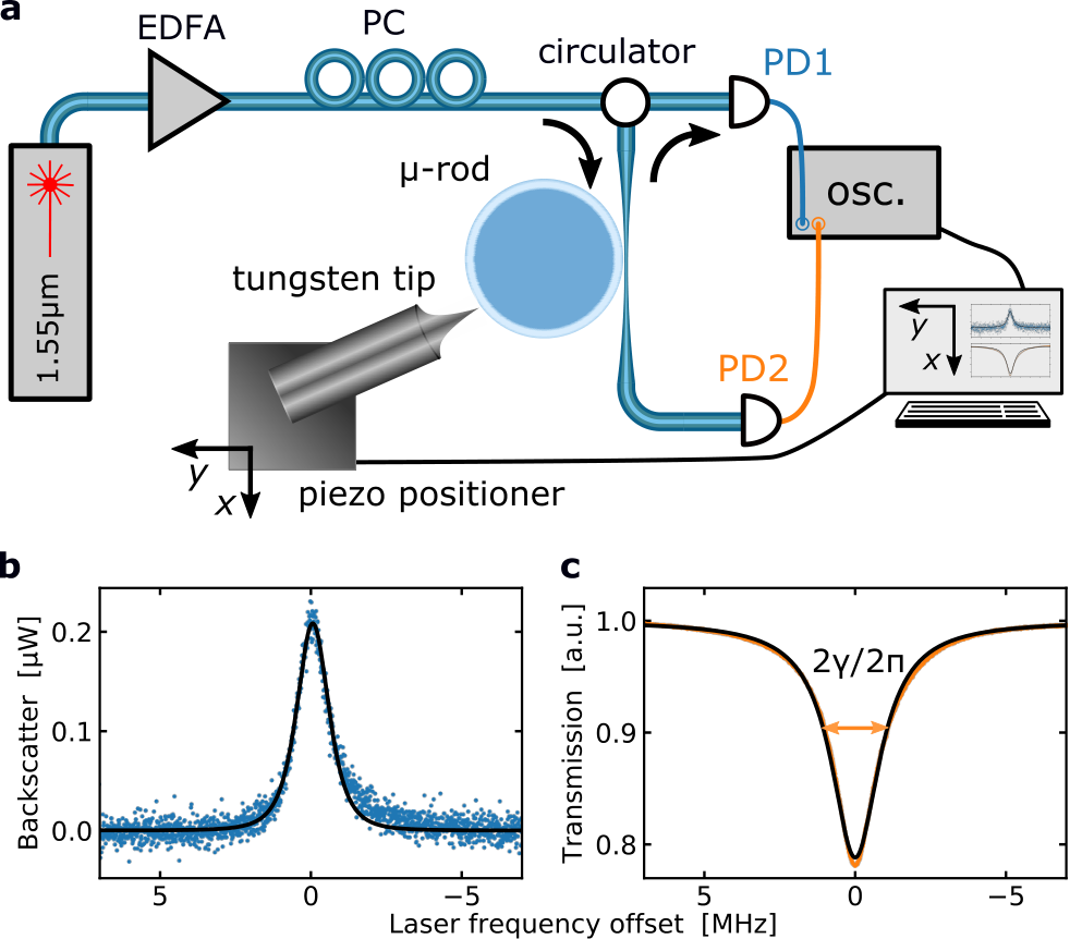
The tip position was raster scanned with a step-size of over a grid of positions in the resonator plane. At each position, transmission and backscattering spectra were simultaneously recorded. The spectra were subsequently fitted with Lorentzian functions (see Materials and methods), as shown for the examples in Fig. 2b and c, to extract the backscatter amplitude , and the pump-resonance half-linewidth , respectively. The resulting data grids for the resonator with are shown in Fig. 3a and b, where each pixel corresponds to a position on the measurement grid. For positions corresponding to , the tip was touching the resonator and sliding along its surface due to the force applied by the piezo positioner.

We performed numerical fitting of the linewidth and amplitude data vs. the two spatial coordinates to determine the position of the resonator surface and radial distance dependences and estimate the periodicity in the fringe pattern and suppression achieved for the backscattering amplitude.
The near-field decay and resonator boundary.
Assuming a linear coupling between the evanescent near field and the tip, we expect the radial dependence of the linewidth to have the same functional dependence as the energy density in the near field. The evanescent electric field from a waveguide decays exponentially with respect to the perpendicular distance from the surface – i.e., for a WGM resonator, the radial distance from the surface, . The evanescent field can be expressed , where is the field strength at the surface, and the decay length is
| (1) |
for a field of vacuum wavelength in a waveguide of refractive index surrounded by air42. With the evanescent field energy density proportional to , we expect the tip-induced loss and backscatter amplitude also to be proportional to this quantity.
However, the prefactors corresponding to coupling back to the resonator clockwise and counter-clockwise directions, coupling to free-space modes, and absorption by the tip are dependent on the size, geometry, and material of the scatterer, as well as on the polarisation of the mode. As propagating modes of different orders than the mode in question have different resonance frequencies, we do not expect light to couple to other WGM modes. Note that in addition to coupling into free space modes, the tip could also induce losses via coupling into non-guided modes within the fused silica. It has previously been shown that for a silica sub-wavelength tip, it is the tip size relative to the mode volume that determines the amount of induced losses34, and furthermore, the tip can cause mode splitting with no change in the quality factor compared to when the tip is not present43, 2.
The linewidth data were fitted with a piecewise function comprising an exponential decay from the resonator surface, and a linear plateau for the tip positions where it is touching the resonator surface (detailed fitting function given in Materials and methods). The fitted interface between the plateau and the exponential decay determined the resonator surface , shown as black lines in Fig. 3a and b. Figure 3c shows cross sections of interpolated values (circles) and the fit (solid) for the linewidth data along the radial direction. The fit gives an exponential decay length for the linewidth of , compared to the calculated near-field power decay length using Eq. 1 for silica at . The steeper decay coefficient in the experimental data compared to the calculated value can be explained by the tip geometry; as the tip approaches the surface, the effective scattering cross section/polarisability increases, leading to an increasingly larger broadening.

Backscatter suppression analysis.
The backscattering data in Fig. 3b show maxima and minima when the tip is in the near-field rather than at the surface due to over-coupling of the tip – i.e., the induced backscattering is larger than the intrinsic backscattering. The radial distance at which the tip minimises the backscattering, , is indicated. The data is fitted with a function which is effectively an exponential decay of coefficient , multiplied with a fringe pattern (see Materials and methods).
The fringe pattern arises due to the relative phase change of the induced backscattering as the tip is translated parallel to the surface (along the azimuthal direction). The expected periodicity of the fringe pattern can be estimated by for silica at our pump wavelength (see Supplementary information). Figures 3d and e show cross sections of interpolated values (circles) and fit (solid) along the radial and azimuthal directions, respectively, for the backscattering data. The fit gave a fringe period of and a decay coefficient for the backscattering of , similar to the linewidth decay length. The current setup is stable enough for the fringe pattern position to remain in place for measurements of at least 45 minutes.
Backscattering suppression in resonators with higher Q-factors.
Figure 4 shows data from a similar measurement in a resonator with . Due to the extremely high Q-factor, this measurement was performed with a lower scanning speed () to avoid ring-down signals, calling for a lower input power () to avoid thermal broadening. The backscattering pattern now shows a decrease in the backscattering for all azimuthal positions as the tip approaches the resonator as the backscattering is linewidth dependent (see Methods) and the linewidth now decreases more than for the resonator in Fig. 3. The maximum backscattering suppression obtained, , is limited by the photodetector noise.
Discussion
Optical microresonators provide prospects for miniaturised sensing and communications systems; however, backscattering compromises the performance of some microresonator-based systems. We have demonstrated a method for coherently suppressing the intrinsic backscattering in an optical WGM microresonator, with the suppression exceeding (limited by photodetectors) from a level where frequency splitting is not resolved. Suppression of backscattering opens opportunities for pure travelling-wave resonators, improving the performance in microresonator applications where backscattering is a limiting factor. These applications include symmetry-breaking-based sensing or non-reciprocal systems, optomechanics applications, laser gyroscopes and dual frequency combs; thus, backscattering suppression enables the development of high-accuracy, portable optical spectroscopy systems, gyroscopes and other sensors. The technique is of particular interest for on-chip resonators, where a scatterer can be permanently integrated on chip to coherently suppress back reflections. In addition, one could envision tuneable on-chip backscattering suppression with a MEMS-based device.
Materials and methods
Resonator and tapered fibre fabrication.
The rod resonators were machined using a CO2 laser, milling commercially available 3--diameter silica glass rods. The procedure follows that of Del’Haye et. al.44, but to reach the highest Q-factor of , the resonator is fabricated in a nitrogen atmosphere, seeking to avoid the formation of near-IR-absorbing OH groups. The rod is fixed to a spindle motor and the glass is evaporated with the focused laser beam. First, the low (high) rod was milled down to a 2.7--diameter (1.7--diameter) cylindrical shape, then the resonator was created by making two ring cuts separated by ().
The tapered fibre was made from a stripped 125--diameter standard single-mode silica optical fibre. The fibre was clamped to stepper motor stages, with a hydrogen flame placed under the fibre to heat it while simultaneously pulling symmetrically from both sides.
Tungsten tip fabrication.
The fabrication of the tungsten tip was based on methods used in scanning tunnelling electron microscopy and atomic force microscopy tip fabrication45, 46. The process relies surface tension to form a meniscus of solution around a piece of tungsten wire and on the aqueous electrochemical reaction
etching the solid tungsten (W) anode through oxidation. When the minimum potential difference () is overcome, the etching rate varies along the wire due to a hydroxide concentration gradient: the etching rate is slower on the top of the meniscus as the ‘hydroxide supply’ is lower in the meniscus above the horizontal surface. This causes a tip shape to form. Further down, the wire is protected as the tungstate () ions fall along the sides of the wire, forming an increasingly dense laminar layer, protecting the lower end of the tip from being etched. When the diameter at the meniscus is decreased sufficiently, gravity will break off the lower part of the wire.
Temper-annealed, 250--diameter, purity polycrystalline tungsten wire was used in the fabrication. The electrolyte was made by dissolving potassium hydroxide (KOH) in deionised water, making a concentration aqueous solution. The second electrode used was tinned copper electrical wire of diameter . The tungsten wire was pre-etched for five seconds at to reduce the surface roughness. After pre-etching, the wire was lifted before continuing the etching process at until the lower part fell off. The total etching time was approximately two minutes.
Experimental setup.
A fibre-coupled external cavity diode laser at , connected to an erbium-doped fibre amplifier, was used as the light source in the experiments. To obtain spectral measurements of the microresonator mode, the frequency of the laser source was scanned by current modulation with a triangular wave signal at (Fig. 3) and (Fig. 4). As the light was subsequently fed into an amplifier operating in saturation, the optical power was kept constant. A polarisation controller was used for optimising coupling to a resonator mode, and a circulator to separate out the backward-propagating light in the tapered fibre for detection. The tapered fibre was mounted on a manual piezo stage to control the coupling to the resonator. Amplified photodetectors and an oscilloscope were used for simultaneously monitoring the transmission and backscattered light.
The tungsten tip was fixed to a polylactic acid (PLA) plastic mount, sitting on a three-axis piezo positioner. The tip position was raster-scanned over a area in the resonator plane, and spectra for backscattering and transmission were obtained for each (Fig. 3) or (Fig. 4) step. The tip-positioner and oscilloscope were simultaneously computer-controlled, allowing a capture time of a few minutes for each of the two measurements reported.
Data analysis.
Least squares fitting procedures were applied to the spectra obtained in the measurement, determining the pump transmission half-linewidth and amplitude , and backscattering amplitude of the cavity for each position in the measurement. No spectrally resolvable mode splitting was observed.
For the pump resonance, a normal Lorentzian dip from a background is used, , where the detuning with respect to the resonance angular frequency is . However, the spectral shape for the backscattering is distorted as it is effectively pumped by a Lorentzian (the pump resonance), resulting in a lineshape in the limit of small backscattering (see Supplementary information for the derivation).
Subsequent to fitting the individual measurements, the grid data of linewidth and backscattering amplitude measurements were fitted. The functions used for the grid data fitting are expressed in a rotated (cartesian) coordinate system at an angle to the measurement coordinate system , where the coordinate transformation is given by
In this coordinate system, the axis is normal to the resonator surface, and can be approximated as the azimuthal position over a short distance compared to the resonator’s radius of curvature. The rotation angle was determined as one of the free parameters of the linewidth grid fit, where the linewidth function expressed in the coordinate system is
with the unperturbed linewidth , decay coefficient , amplitude of the exponential decay , linear slope of the plateau at the resonator surface , and the coordinate system offset as free parameters.
The relative backscattering amplitude grid was subsequently fitted with the parameters and fixed to the values obtained from the linewidth fit. Only the portion of data outside the resonator boundary, , was fitted. The function fitted for the backscattering amplitude is derived in the Supplementary information, and reads
where is the fitted linewidth function, and the coupling from the forward- to the back-propagating mode
where is the fitted linewidth function, the intrinsic backscattering strength, is a position-dependent phase responsible for the fringe pattern, in which is a radially dependent phase accounting for the shape of the tip and/or drift. The period of the fringe pattern is given by .
References
- Heylman et al. (2017) K. D. Heylman, K. A. Knapper, E. H. Horak, M. T. Rea, S. K. Vanga, and R. H. Goldsmith, Optical Microresonators for Sensing and Transduction: A Materials Perspective, Adv. Mater. 29, 1700037 (2017).
- Foreman et al. (2015) M. R. Foreman, J. D. Swaim, and F. Vollmer, Whispering gallery mode sensors, Adv. Opt. Photonics 7, 168 (2015).
- Righini et al. (2011) G. C. Righini, Y. Dumeige, P. Féron, M. Ferrari, G. N. Conti, D. Ristic, and S. Soria, Whispering Gallery Mode microresonators: Fundamentals and applications, Riv. del Nuovo Cim. 34, 435 (2011).
- Kippenberg et al. (2011) T. J. Kippenberg, R. Holzwarth, and S. A. Diddams, Microresonator-Based Optical Frequency Combs, Science 332, 555 (2011).
- Matsko et al. (2007) A. B. Matsko, A. A. Savchenkov, N. Yu, and L. Maleki, Whispering-gallery-mode resonators as frequency references. I. Fundamental limitations, J. Opt. Soc. Am. B 24, 1324 (2007).
- Del’Haye et al. (2007) P. Del’Haye, A. Schliesser, O. Arcizet, T. Wilken, R. Holzwarth, and T. J. Kippenberg, Optical frequency comb generation from a monolithic microresonator, Nature 450, 1214 (2007).
- Aspelmeyer et al. (2014) M. Aspelmeyer, T. J. Kippenberg, and F. Marquardt, Cavity optomechanics, Rev. Mod. Phys. 86, 1391 (2014).
- Wilson et al. (2015) D. J. Wilson, V. Sudhir, N. Piro, R. Schilling, A. Ghadimi, and T. J. Kippenberg, Measurement-based control of a mechanical oscillator at its thermal decoherence rate, Nature 524, 325 (2015).
- Enzian et al. (2019) G. Enzian, M. Szczykulska, J. Silver, L. Del Bino, S. Zhang, I. A. Walmsley, P. Del’Haye, and M. R. Vanner, Observation of Brillouin optomechanical strong coupling with an 11 GHz mechanical mode, Optica 6, 7 (2019).
- Strekalov et al. (2016) D. V. Strekalov, C. Marquardt, A. B. Matsko, H. G. L. Schwefel, and G. Leuchs, Nonlinear and quantum optics with whispering gallery resonators, J. Opt. 18, 123002 (2016).
- Fürst et al. (2011) J. U. Fürst, D. V. Strekalov, D. Elser, A. Aiello, U. L. Andersen, C. Marquardt, and G. Leuchs, Quantum light from a whispering-gallery-mode disk resonator, Phys. Rev. Lett. 106, 113901 (2011).
- Marin-Palomo et al. (2017) P. Marin-Palomo, J. N. Kemal, M. Karpov, A. Kordts, J. Pfeifle, M. H. P. Pfeiffer, P. Trocha, S. Wolf, V. Brasch, M. H. Anderson, et al., Microresonator-based solitons for massively parallel coherent optical communications, Nature 546, 274 (2017).
- Reimer et al. (2016) C. Reimer, M. Kues, P. Roztocki, B. Wetzel, F. Grazioso, B. E. Little, S. T. Chu, T. Johnston, Y. Bromberg, L. Caspani, D. J. Moss, and R. Morandotti, Generation of multiphoton entangled quantum states by means of integrated frequency combs, Science 351, 1176 (2016).
- Pfeifle et al. (2014) J. Pfeifle, V. Brasch, M. Lauermann, Y. Yu, D. Wegner, T. Herr, K. Hartinger, P. Schindler, J. Li, D. Hillerkuss, R. Schmogrow, C. Weimann, R. Holzwarth, W. Freude, J. Leuthold, T. J. Kippenberg, and C. Koos, Coherent terabit communications with microresonator Kerr frequency combs, Nat. Photonics 8, 375 (2014).
- Mohageg et al. (2007) M. Mohageg, A. Savchenkov, and L. Maleki, Coherent backscattering in lithium niobate whispering-gallery-mode resonators, Opt. Lett. 32, 2574 (2007).
- Kippenberg et al. (2002) T. J. Kippenberg, S. M. Spillane, and K. J. Vahala, Modal coupling in traveling-wave resonators, Opt. Lett. 27, 1669 (2002).
- Gorodetsky et al. (2000) M. L. Gorodetsky, A. D. Pryamikov, and V. S. Ilchenko, Rayleigh scattering in high-Q microspheres, J. Opt. Soc. Am. B 17, 1051 (2000).
- Weiss et al. (1995) D. S. Weiss, V. Sandoghdar, J. Hare, V. Lefèvre-Seguin, J.-M. Raimond, and S. Haroche, Splitting of high-Q Mie modes induced by light backscattering in silica microspheres, Opt. Lett. 20, 1835 (1995).
- Chow et al. (1985) W. W. Chow, J. Gea-Banacloche, L. M. Pedrotti, V. E. Sanders, W. Schleich, and M. O. Scully, The ring laser gyro, Rev. Mod. Phys. 57, 61 (1985).
- Dell’Olio et al. (2014) F. Dell’Olio, T. Tatoli, C. Ciminelli, and M. Armenise, Recent advances in miniaturized optical gyroscopes, J. Eur. Opt. Soc. Rapid 9, 14013 (2014).
- Liang et al. (2017) W. Liang, V. S. Ilchenko, A. A. Savchenkov, E. Dale, D. Eliyahu, A. B. Matsko, and L. Maleki, Resonant microphotonic gyroscope, Optica 4, 114 (2017).
- Yang et al. (2017) Q.-F. Yang, X. Yi, K. Y. Yang, and K. Vahala, Counter-propagating solitons in microresonators, Nat. Photonics 11, 560 (2017).
- Lucas et al. (2018) E. Lucas, G. Lihachev, R. Bouchand, N. G. Pavlov, A. S. Raja, M. Karpov, M. L. Gorodetsky, and T. J. Kippenberg, Spatial multiplexing of soliton microcombs, Nat. Photonics 12, 699 (2018).
- Del Bino et al. (2017) L. Del Bino, J. M. Silver, S. L. Stebbings, and P. Del’Haye, Symmetry Breaking of Counter-Propagating Light in a Nonlinear Resonator, Sci. Rep. 7, 43142 (2017).
- Kaplan and Meystre (1981) A. E. Kaplan and P. Meystre, Enhancement of the Sagnac effect due to nonlinearly induced nonreciprocity. Opt. Lett. 6, 590 (1981).
- Moroney et al. (2020) N. Moroney, L. Del Bino, M. Woodley, G. Ghalanos, J. Silver, A. Svela, S. Zhang, and P. Del’Haye, Logic Gates based on Interaction of Counterpropagating Light in Microresonators, J. Light. Techn. (2020), 10.1109/JLT.2020.2975119.
- Del Bino et al. (2020) L. Del Bino, N. Moroney, and P. Del’Haye, Optical memories and switching dynamics of counterpropagating light states in microresonators, (2020), 2002.02954 .
- Del Bino et al. (2018) L. Del Bino, J. M. Silver, M. T. M. Woodley, S. L. Stebbings, X. Zhao, and P. Del’Haye, Microresonator isolators and circulators based on the intrinsic nonreciprocity of the Kerr effect, Optica 5, 279 (2018).
- Kim et al. (2017) E. Kim, M. D. Baaske, and F. Vollmer, Towards next-generation label-free biosensors: recent advances in whispering gallery mode sensors, Lab Chip 17, 1190 (2017).
- Little et al. (2000) B. E. Little, S. T. Chu, W. Pan, and Y. Kokubun, Microring resonator arrays for VLSI photonics, IEEE Photonics Technol. Lett. 12, 323 (2000).
- Matres and Sorin (2017) J. Matres and W. V. Sorin, Simple model for ring resonators backscatter, Opt. Express 25, 3242 (2017).
- MacKintosh and John (1988) F. C. MacKintosh and S. John, Coherent backscattering of light in the presence of time-reversal-noninvariant and parity-nonconserving media, Phys. Rev. B 37, 1884 (1988).
- Golubentsev (1984) A. A. Golubentsev, Suppression of interference effects in multiple scattering of light, Sov. Phys. JETP 59, 26 (1984).
- Mazzei et al. (2007) A. Mazzei, S. Götzinger, L. de S. Menezes, G. Zumofen, O. Benson, and V. Sandoghdar, Controlled coupling of counterpropagating whispering-gallery modes by a single Rayleigh scatterer: A classical problem in a quantum optical light, Phys. Rev. Lett. 99, 173603 (2007).
- Zhu et al. (2010) J. Zhu, Ş. K. Özdemir, L. He, and L. Yang, Controlled manipulation of mode splitting in an optical microcavity by two Rayleigh scatterers, Opt. Express 18, 23535 (2010).
- Peng et al. (2016) B. Peng, Ş. K. Özdemir, M. Liertzer, W. Chen, J. Kramer, H. Yılmaz, J. Wiersig, S. Rotter, and L. Yang, Chiral modes and directional lasing at exceptional points, Proc. Natl. Acad. Sci. 113, 6845 (2016).
- Wang et al. (2020) C. Wang, X. Jiang, G. Zhao, M. Zhang, C. W. Hsu, B. Peng, A. D. Stone, L. Jiang, and L. Yang, Electromagnetically induced transparency at a chiral exceptional point, Nat. Phys. (2020), 10.1038/s41567-019-0746-7.
- Kim et al. (2019) S. Kim, J. M. Taylor, and G. Bahl, Dynamic suppression of Rayleigh backscattering in dielectric resonators, Optica 6, 1016 (2019).
- Wiersig (2011) J. Wiersig, Structure of whispering-gallery modes in optical microdisks perturbed by nanoparticles, Phys. Rev. A 84, 063828 (2011).
- Spillane et al. (2003) S. M. Spillane, T. J. Kippenberg, O. J. Painter, and K. J. Vahala, Ideality in a fiber-taper-coupled microresonator system for application to cavity quantum electrodynamics, Phys. Rev. Lett. 91, 043902 (2003).
- Zhu et al. (2019) J. Zhu, M. Zohrabi, K. Bae, T. M. Horning, M. B. Grayson, W. Park, and J. T. Gopinath, Nonlinear characterization of silica and chalcogenide microresonators, Optica 6, 716 (2019).
- de Fornel (2001) F. de Fornel, Evanescent Waves, Optical Sciences, Vol. 73 (Springer-Verlag, 2001).
- Götzinger et al. (2002) S. Götzinger, O. Benson, and V. Sandoghdar, Influence of a sharp fiber tip on high-Q modes of a microsphere resonator, Opt. Lett. 27, 80 (2002).
- Del’Haye et al. (2013) P. Del’Haye, S. A. Diddams, and S. B. Papp, Laser-machined ultra-high-Q microrod resonators for nonlinear optics, Appl. Phys. Lett. 102, 221119 (2013).
- Ibe et al. (1990) J. P. Ibe, P. P. Bey, S. L. Brandow, R. A. Brizzolara, N. A. Burnham, D. P. DiLella, K. P. Lee, C. R. K. Marrian, and R. J. Colton, On the electrochemical etching of tips for scanning tunneling microscopy, J. Vac. Sci. Technol. A 8, 3570 (1990).
- Hagedorn et al. (2011) T. Hagedorn, E. Ouali, W. Paul, and D. Oliver, Refined tip preparation by electrochemical etching and ultrahigh vacuum treatment to obtain atomically sharp tips for scanning tunneling microscope and atomic force microscope, Rev. Sci. Instrum. 82, 113903 (2011).
Acknowledgements
This work has been supported by the National Physical Laboratory Strategic Research Programme and the European Research Council (CounterLight, 756966), Marie Skłodowska-Curie Actions (MSCA) (CoLiDR, 748519) and UK Research and Innovation (MR/S032924/1). A.Ø.S. is supported by an Aker Scholarship and the Engineering and Physical Sciences Research Council (EPSRC) via the Quantum Systems Engineering programme at Imperial College London. J.M.S. acknowledges funding via a Royal Society of Engineering fellowship. L.D.B. and M.T.M.W. are supported by the EPSRC through the Centre for Doctoral Training in Applied Photonics. S.Z. acknowledges funding via an MSCA fellowship (GA-2015-713694).
Author contributions
A.Ø.S. and P.D’H. conceived the experiments. A.Ø.S., L.D.B., J.M.S., S.Z. and M.T.M.W. designed and constructed the experiments. A.Ø.S. performed the experiments and analysed the results with J.M.S. All authors discussed the project, its results, and contributed to the manuscript.
Data availability
The data that supports this Article is available from the corresponding author upon reasonable request.
Competing interests
The authors declare that they have no competing financial interests.
Additional information
Correspondence and requests for materials should be addressed to P.D’H. (email: pascal.delhaye@mpl.mpg.de).
Supplementary information
The pump and backscatter lineshapes.
Following a time-dependent approach1, 2, 3, the steady-state equations of motion for the two circulating, counter-propagating fields , both detuned by from the pump and perturbed by complex scattering coefficients , can be expressed as
when a field is pumping the clockwise propagating mode. Inverting the matrix, we obtain
In the small-backscattering regime , this gives
| (S1) |
where are proportional to the powers circulating in the respective directions.
The output fields in the taper from the cw and ccw directions can be expressed1 using the taper coupling linewidth ,
To find the lineshapes of the output fields, insert Eq. S1 and take the modulus squared to obtain
The total linewidth has two components, the intrinsic losses and the taper coupling , such that . Furthermore, the coupling efficiency , giving
| (S2) |
This shows that the transmitted clockwise pump has a dip with a normal Lorentzian lineshape, whereas the backscattered power will exhibit a peak with a squared Lorentzian lineshape of amplitude .
Derivation of the backscattering fitting function.
From Eq. S2, we are expecting the backscattering power at resonance to be proportional to . The coupling coefficient has two contributions, an intrinsic , which by a suitable choice of the relative phase between the cw and ccw basis states can be made to be real, and a tip-induced . The tip-induced coupling is expected to follow , where is a position-dependent phase responsible for the fringe pattern, in which is a radially dependent phase accounting for the shape of the tip and/or drift. Coherently adding the two contributions, , we obtain
As only the portion of data outside the resonator boundary, , was fitted, the fitting function for the backscattering amplitude can be expressed as
| (S3) |
in which is the fitted linewidth function.
Expected period of the fringe pattern.
The fringe pattern in the backscattering arises from the term in Eq. S3, where is the phase of the backscattered light from the tip. We find the periodicity of the fringe pattern with respect to the azimuthal position by considering the distance between subsequent maxima. As the phase of the backscattered light depends on the phase of the clockwise mode relative to the ccw mode at the position of each part of the tip involved in backscattering, this relative phase difference varies with by , where is the optical wavenumber. Hence, the distance between maxima is given by .
For a resonator of material with refractive index , the optical wavenumber for the vacuum wavelength (the approximation is due to the transverse confinement of the mode), giving a period .
References
- Rabus (2007) D. G. Rabus, Integrated Ring Resonators, Optical Sciences, Vol. 127 (Springer, 2007).
- Wiersig (2011) J. Wiersig, Structure of whispering-gallery modes in optical microdisks perturbed by nanoparticles, Phys. Rev. A 84, 063828 (2011).
- Woodley et al. (2018) M. T. M. Woodley, J. M. Silver, L. Hill, F. m. c. Copie, L. Del Bino, S. Zhang, G.-L. Oppo, and P. Del’Haye, Universal symmetry-breaking dynamics for the Kerr interaction of counterpropagating light in dielectric ring resonators, Phys. Rev. A 98, 053863 (2018).