跳到论文正文
W Papers独立论文阅读器 arXiv:2002.10020 论文正文 计算阅读时间 · 0%
引用这篇论文根据当前论文元数据生成,正式投稿前建议核对。


License: arXiv.org perpetual non-exclusive license
arXiv:2002.10020v1 [eess.SP] 24 Feb 2020

Optimal Jammer Placement in UAV-assisted Relay Networks

Seyyedali Hosseinalipour Affiliation: ECE Department
North Carolina State University
Raleigh, USA
shossei3@ncsu.edu
   Ali Rahmati Affiliation: ECE Department
North Carolina State University
Raleigh, USA
arahmat@ncsu.edu
   Huaiyu Dai Affiliation: ECE Department
North Carolina State University
Raleigh, USA
hdai@ncsu.edu
Abstract

We consider the relaying application of unmanned aerial vehicles (UAVs), in which UAVs are placed between two transceivers (TRs) to increase the throughput of the system. Instead of studying the placement of UAVs as pursued in existing literature, we focus on investigating the placement of a jammer or a major source of interference on the ground to effectively degrade the performance of the system, which is measured by the maximum achievable data rate of transmission between the TRs. We demonstrate that the optimal placement of the jammer is in general a non-convex optimization problem, for which obtaining the solution directly is intractable. Afterward, using the inherent characteristics of the signal-to-interference ratio (SIR) expressions, we propose a tractable approach to find the optimal position of the jammer. Based on the proposed approach, we investigate the optimal positioning of the jammer in both dual-hop and multi-hop UAV relaying settings. Numerical simulations are provided to evaluate the performance of our proposed method.

I Introduction

Applications of unmanned aerial vehicles (UAVs) in wireless communication has attracted lots of attentions due to their ease of deployment and 3D movement capability, where one of their recent applications is data relaying [1]. On the other hand, jamming can degrade the performance of relay networks, which should be carefully addressed in practice. Although jamming and anti-jamming approaches have been investigated in wireless networks [2, 3, 4], in the context of UAV-assisted networks, the current state of the art still lacks maturity [5].

Optimal jammer placement has been studied in the context of network partitioning in wireless networks, e.g., [2], [3]. In these works, the authors investigate the effective jammer positioning to partition a wireless network into multiple residual sub-networks with a constraint on the number of jammers. It is shown that there is a trade-off between the number of required jammers and the maximum order, i.e., the number of functional nodes, of the residual sub-networks. Another application of jamming is providing a secure communication for sensitive information, where the usage of friendly jammers to protect sensitive communications is common [4, 6]. In [4], the placement and power consumption of jammers is optimized in space and time to guarantee information-theoretic security for a secure communication. The aim is to prevent the eavesdroppers outside the protected zone from having a knowledge about the transmitted data. A similar problem is studied in [6], where jamming via transmitting artificial noise is considered to protect the communication from eavesdroppers. More discussions on (anti-)jamming techniques can be found in [7]. Moreover, there is a body of literature devoted to jammer localization, i.e., detecting the location of jammers, in wireless networks [8].

In the context of UAV relay networks, we were among the first to study the placement optimization and trajectory design for UAV relays to evade the interference caused by the jammers [9, 10, 11, 12]. Considering a major source of interference (MSI), the optimal placement of the UAV relays along with identifying the minimum number of required UAVs to satisfy a desired communication quality are studied in [9, 10]. A joint power allocation and trajectory design is proposed in [11, 12] to evade the interference caused by another established wireless network. In [13], the optimal position and jamming power of a legitimate UAV monitor are obtained to maximize the average surveillance rate. In [14], a scenario is studied where a UAV transmits artificial noise to confuse the ground eavesdropper for protection of the transmitted data. In [15], an anti-jamming approach is proposed in which the UAVs dynamically adjust their trajectory. Nevertheless, none of the aforementioned works investigates efficient degradation of the communication quality of UAV relay networks from the perspective of a jammer, which is our main motivation.

In this paper, we consider a terrestrial jammer or MSI that aims to effectively deteriorate the communication quality of a UAV-assisted relay network working in the decode-and-forward relaying mode. We consider a two-way communication scenario, where the UAVs function as two-way relays between two terrestrial transceivers. The goal is to obtain the optimal placement of the terrestrial jammer to minimize the maximum achievable data rate of transmission between the terrestrial transceivers. We note that the optimal jammer placement problem belongs to the family of non-convex optimization problems, for which direct derivation of the solution is in general intractable. Using the inherent characteristics of the signal-to-interference ratio (SIR) expressions that result in piece-wise convexity of the objective function, we propose two efficient algorithms with polynomial complexity to obtain the optimal position of the jammer in the dual-hop and multi-hop UAV relay networks. Numerical simulations are conducted to reveal the performance of our proposed approach.

II Preliminaries and Problem Formulation

II-A Preliminaries

We consider a two-way communication between a pair of transceivers (TRs), named TR_1 and TR_2, both engaged in transmitting and receiving the data. We assume a left-handed coordination system (x,y,h)(x,y,h), and, without loss of generality, TR_1 and TR_2 are assumed to be located at (0,0,0)(0,0,0) and (D,0,0)(D,0,0), respectively. To improve the quality of communication, a set of UAV relays are placed between the TRs. We aim to effectively place a jammer/MSI on the ground to maximally deteriorate the communication performance of the system. Let (xMSI,yMSI,hMSI=0)(x_{{}_{\textrm{MSI}}},y_{{}_{\textrm{MSI}}},{h}_{{}_{\textrm{MSI}}}=0) denote the position of the MSI.11 1 Considering the MSI to be a flying UAV with a fixed altitude hMSI=h^MSI{h}_{{}_{\textrm{MSI}}}=\hat{h}_{{}_{\textrm{MSI}}} incurs minor modifications in the derivations. The transmission powers of TR_1, TR_2, and the MSI are denoted by pTR_1p_{{}_{\textrm{TR\_1}}}, pTR_2p_{{}_{\textrm{TR\_2}}}, and pMSIp_{{}_{\textrm{MSI}}}, respectively. We consider both the line-of-sight (LoS) and the non-line-of-sight (NLoS) channel models, for which the path-loss is given by [16]:

LLoSi,j=μLoSdi,jα,LNLoSi,j=μNLoSdi,jα,L^{\textrm{LoS}}_{i,j}=\mu_{{}_{\textrm{LoS}}}d_{i,j}^{\alpha},\;\;L^{\textrm{NLoS}}_{i,j}=\mu_{{}_{\textrm{NLoS}}}d_{i,j}^{\alpha},\vskip-2.84526pt (1)

where μLoS≜CLoS(4πfc/c)α\mu_{{}_{\textrm{LoS}}}\triangleq C_{{}_{\textrm{LoS}}}\left(4\pi f_{c}/c\right)^{\alpha}, μNLoS≜CNLoS(4πfc/c)α\mu_{{}_{\textrm{NLoS}}}\triangleq C_{{}_{\textrm{NLoS}}}\left(4\pi f_{c}/c\right)^{\alpha}, CLoSC_{{}_{\textrm{LoS}}} (CNLoSC_{{}_{\textrm{NLoS}}}) is the excessive path loss factor incurred by shadowing, scattering, etc., in the LoS (NLoS) link, fcf_{c} is the carrier frequency, cc is the speed of light, α=2\alpha=2 is the path-loss exponent, and di,jd_{i,j} is the Euclidean distance between node ii and node jj. The link between two UAVs (air-to-air) is modeled using the LoS model, while the link between the MSI and a TR (ground-to-ground) is modeled based on the NLoS model. For the link between a UAV and the TRs or the MSI (air-to-ground and ground-to-air), we denote the path loss between a UAV ii and terrestrial node jj by ηNLoSdi​j2\eta_{{}_{\textrm{NLoS}}}d_{ij}^{2} (for more information on ηNLoS\eta_{{}_{\textrm{NLoS}}} please refer to [10] and references therein). Due to the geographical limitations, direct communication between the TRs is not considered. While the above channel models are relatively simple, they represent the current art in UAV modeling, and facilitate the derivation of many interesting results in current literature, e.g., [1, 16].

II-B Problem Formulation

As shown in Fig. 1, consider NN UAVs between the TRs, where the location of UAVi\textrm{UAV}_{i} is denoted by (xi,yi,zi)(x_{i},y_{i},z_{i}). Let us define Link_1 as the transmission link from TR_1 to TR_2 (when TR_1 acts as a transmitter and TR_2 acts as a receiver), and Link_2 as the transmission link from TR_2 to TR_1. It is assumed that the UAVs utilize the same frequency but different time slots to avoid mutual interference among the UAVs. We consider an interference limited environment, where the power of noise is negligible compared to that of interference caused by the MSI, and thus the SIR is used to describe the quality of communication. For Link_1, let SIRi\textrm{SIR}_{i} denote the SIR at UAVi\textrm{UAV}_{i}, 1≤i≤N1\leq i\leq N, and SIRN+1\textrm{SIR}_{N+1} denote the SIR at TR_2. Similarly, for Link_2, SIRN+2+i\textrm{SIR}_{N+2+i} denotes the SIR at UAVN−i\textrm{UAV}_{N-i}, 0≤i≤N−10\leq i\leq N-1, and SIR2​N+2\textrm{SIR}_{2N+2} denotes the SIR at TR_1. Assuming decode-and-forward relaying, the SIR of Link_1 and Link_2 are given by:

SIRLink_1(xMSI,yMSI)=min{SIRi(xMSI,yMSI):1≤i≤N+1},\hskip-39.5493pt\textrm{SIR}_{\textrm{Link\_1}}(x_{{}_{\textrm{MSI}}},{y}_{{}_{\textrm{MSI}}})=\min\{\textrm{SIR}_{i}(x_{{}_{\textrm{MSI}}},{y}_{{}_{\textrm{MSI}}}):1\leq i\leq N+1\},\hskip-28.45274pt (2)
SIRLink_2(xMSI,yMSI)=min{SIRN+i+2(xMSI,yMSI):0≤i≤N}.\hskip-39.5493pt\textrm{SIR}_{\textrm{Link\_2}}(x_{{}_{\textrm{MSI}}},{y}_{{}_{\textrm{MSI}}})=\min\{\textrm{SIR}_{N+i+2}(x_{{}_{\textrm{MSI}}},{y}_{{}_{\textrm{MSI}}}):0\leq i\leq N\}.\hskip-28.45274pt (3)

The goal of the jammer is to locate itself to effectively degrade the maximum achievable data rate of transmission between the TRs. Assuming the same bandwidth for both links, this is equivalent to minimizing the maximum value of the SIR of the links denoted by SIRmax=max⁡(SIRLink_1,SIRLink_2)\textrm{SIR}_{\textrm{max}}=\max(\textrm{SIR}_{\textrm{Link\_1}},\textrm{SIR}_{\textrm{Link\_2}}). Thus,

(x∗MSI,y∗MSI)=arg​minxMSI,yMSImax{\displaystyle(x^{*}_{{}_{\textrm{MSI}}},y^{*}_{{}_{\textrm{MSI}}})=\argmin_{x_{{}_{\textrm{MSI}}},y_{{}_{\textrm{MSI}}}}\hskip 5.69054pt\max\{ SIRLink_1(xMSI,yMSI),\displaystyle\textrm{SIR}_{\textrm{Link\_1}}(\hskip-1.13809ptx_{{}_{\textrm{MSI}}},{y}_{{}_{\textrm{MSI}}}\hskip-1.13809pt), (4)
SIRLink_2(xMSI,yMSI)}.\displaystyle\textrm{SIR}_{\textrm{Link\_2}}(\hskip-1.13809ptx_{{}_{\textrm{MSI}}},{y}_{{}_{\textrm{MSI}}}\hskip-1.13809pt)\hskip-1.13809pt\}.

The SIR expressions are convex functions with respect to (w.r.t) xMSIx_{{}_{\textrm{MSI}}} and yMSIy_{{}_{\textrm{MSI}}} (see (21)). However, since the minimum of convex functions is not necessary convex, SIRLink_1\textrm{SIR}_{\textrm{Link\_1}} and SIRLink_2\textrm{SIR}_{\textrm{Link\_2}} are, in general, non-convex functions w.r.t the position of the jammer. This results in non-convexity of our main problem in (4), which makes classic convex optimization techniques irrelevant and obtaining the solution non-trivial. In this work, we aim to develop a tractable analytical approach to solve this problem. Given the fact that tackling the problem where xMSI,yMSIx_{{}_{\textrm{MSI}}},y_{{}_{\textrm{MSI}}} are both variable is highly nontrivial, we fix one of those coordinates, which is yMSIy_{{}_{\textrm{MSI}}} in this work such that yMSI=y^MSIy_{{}_{\textrm{MSI}}}=\hat{y}_{{}_{\textrm{MSI}}}, and obtain x∗MSIx^{*}_{{}_{\textrm{MSI}}}. Even with this assumption, the problem remains to be non-convex and non-trivial. Given the notable low complexity of our proposed method, one can obtain x∗MSIx^{*}_{{}_{\textrm{MSI}}} for a set of given yMSIy_{{}_{\textrm{MSI}}}-s and choose the best solution among them. Also, the proposed methodology can be easily applied to the case where xMSIx_{{}_{\textrm{MSI}}} is fixed and yMSIy_{{}_{\textrm{MSI}}} is variable. Thus, one can set xMSI=x∗MSIx_{{}_{\textrm{MSI}}}=x^{*}_{{}_{\textrm{MSI}}} to obtain the corresponding y∗MSIy^{*}_{{}_{\textrm{MSI}}} in a successive manner. Throughout, we assume that the MSI is mounted on a vehicle with the feasible moving area confined by −x−j​a​m≤xMSI≤x+j​a​m-x^{-}_{jam}\leq x_{{}_{\textrm{MSI}}}\leq x^{+}_{jam}, where xj​a​m+≥D,−xj​a​m−≤0x^{+}_{jam}\geq D,~-x^{-}_{jam}\leq 0. To facilitate the discussion, we first investigate the problem in the dual-hop setting, which itself is of interest, and then extend the study to the multi-hop setting.
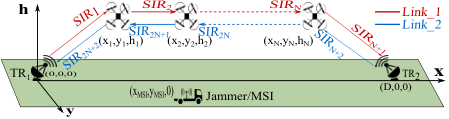
Refer to caption
Fig. 1: A jammer/MSI that aims to deteriorate the communication performance in multi-hop UAV relay setting.

III Jammer Placement in Dual-hop Setting

Consider the jammer placement in the dual-hop setting, where the data is relayed via a single UAV located at (xu,yu,hu)(x_{u},y_{u},h_{u}) with transmission power pup_{u} (see Fig. 2). The SIR expressions are given by:

SIR1(xMSI,y^MSI)=pTR_1((xu−xMSI)2+(y^MSI−yu)2+hu2)pMSI(xu2+yu2+hu2),\displaystyle\textrm{SIR}_{1}(x_{{}_{\textrm{MSI}}},\hat{y}_{{}_{\textrm{MSI}}})\hskip-2.84526pt=\hskip-2.84526pt\frac{p_{{}_{\textrm{TR\_1}}}\hskip-0.34142pt\left(\hskip-0.42677pt\left(\hskip-0.42677ptx_{u}-x_{{}_{\textrm{MSI}}}\hskip-0.42677pt\right)^{2}\hskip-0.42677pt+\hskip-0.39833pt\left(\hat{y}_{{}_{\textrm{MSI}}}-y_{u}\right)^{2}\hskip-0.42677pt+\hskip-0.34142pth_{u}^{2}\hskip-0.42677pt\right)}{p_{{}_{\textrm{MSI}}}\left(x_{u}^{2}+y_{u}^{2}+h_{u}^{2}\right)}, (5)
SIR2(xMSI,y^MSI)=pu(y^2MSI+(D−xMSI)2)pMSI((D−xu)2+y2u+h2u)(ηNLoSμNLoS),\displaystyle\hskip-22.76219pt\textrm{SIR}_{2}(x_{{}_{\textrm{MSI}}},\hat{y}_{{}_{\textrm{MSI}}})=\hskip-2.84526pt\frac{\hskip-0.42677ptp_{u}\hskip-0.28453pt\left(\hskip-0.42677pt\hat{y}^{2}_{{}_{\textrm{MSI}}}\hskip-0.42677pt+\hskip 0.0pt(\hskip-0.36989ptD-x_{{}_{\textrm{MSI}}}\hskip-0.36989pt)^{2}\hskip-0.36989pt\right)}{\hskip-0.28453ptp_{{}_{\textrm{MSI}}}\hskip-0.42677pt\left(\left(\hskip-0.39833ptD\hskip-0.34142pt-\hskip-0.34142ptx_{u}\hskip-0.36989pt\right)\hskip-0.34142pt^{2}\hskip-0.34142pt+y^{2}_{u}+\hskip-0.56905pth^{2}_{u}\hskip-0.56905pt\right)\hskip 0.0pt\left(\frac{\hskip-0.42677pt\eta_{{}_{\textrm{NLoS}}}}{\hskip-0.42677pt\mu_{{}_{\textrm{NLoS}}}}\hskip-0.48369pt\right)}, (6)
SIR3(xMSI,y^MSI)=pTR_2((xu−xMSI)2+(y^MSI−yu)2+hu2)pMSI((D−xu)2+y2u+hu2),\displaystyle\hskip 5.12149pt\textrm{SIR}_{3}(x_{{}_{\textrm{MSI}}},\hat{y}_{{}_{\textrm{MSI}}})=\hskip-2.84526pt\frac{p_{{}_{\textrm{TR\_2}}}\hskip-0.34142pt\left(\hskip-0.42677pt\left(\hskip-0.42677ptx_{u}-x_{{}_{\textrm{MSI}}}\hskip-0.42677pt\right)^{2}\hskip-0.42677pt+\hskip-0.39833pt\left(\hat{y}_{{}_{\textrm{MSI}}}-y_{u}\right)^{2}\hskip-0.42677pt+\hskip-0.34142pth_{u}^{2}\hskip-0.42677pt\right)}{p_{{}_{\textrm{MSI}}}\left((D-x_{u})^{2}+y^{2}_{u}+h_{u}^{2}\right)}, (7)
SIR4(xMSI,y^MSI)=pu(y^2MSI+xMSI2)pMSI(xu2+y2u+h2u)(ηNLoSμNLoS).\displaystyle\hskip-45.5244pt\textrm{SIR}_{4}(x_{{}_{\textrm{MSI}}},\hat{y}_{{}_{\textrm{MSI}}})=\hskip-2.84526pt\frac{\hskip-0.42677ptp_{u}\hskip-0.28453pt\left(\hskip-0.42677pt\hat{y}^{2}_{{}_{\textrm{MSI}}}\hskip-0.42677pt+\hskip 0.0ptx_{{}_{\textrm{MSI}}}^{2}\hskip-0.36989pt\right)}{\hskip-0.28453ptp_{{}_{\textrm{MSI}}}\hskip-0.42677pt\left(x_{u}^{2}\hskip-0.34142pt+y^{2}_{u}+\hskip-0.56905pth^{2}_{u}\hskip-0.56905pt\right)\hskip 0.0pt\left(\frac{\hskip-0.42677pt\eta_{{}_{\textrm{NLoS}}}}{\hskip-0.42677pt\mu_{{}_{\textrm{NLoS}}}}\hskip-0.48369pt\right)}. (8)
Refer to caption
Fig. 2: A jammer/MSI that aims to deteriorate the communication performance in dual-hop UAV relay setting.

Consequently, the SIR of Link_1 and Link_2 are given by:

SIRLink_1(xMSI,y^MSI)=min{\displaystyle\textrm{SIR}_{\textrm{Link\_1}}(x_{{}_{\textrm{MSI}}},\hat{y}_{{}_{\textrm{MSI}}})=\min\{ SIR1(xMSI,y^MSI),SIR2(xMSI,y^MSI)},\displaystyle\textrm{SIR}_{1}(x_{{}_{\textrm{MSI}}},\hat{y}_{{}_{\textrm{MSI}}}),\textrm{SIR}_{2}(x_{{}_{\textrm{MSI}}},\hat{y}_{{}_{\textrm{MSI}}})\}, (9)
SIRLink_2(xMSI,y^MSI)=min{\displaystyle\textrm{SIR}_{\textrm{Link\_2}}(x_{{}_{\textrm{MSI}}},\hat{y}_{{}_{\textrm{MSI}}})=\min\{ SIR3(xMSI,y^MSI),SIR4(xMSI,y^MSI)},\displaystyle\textrm{SIR}_{3}(x_{{}_{\textrm{MSI}}},\hat{y}_{{}_{\textrm{MSI}}}),\textrm{SIR}_{4}(x_{{}_{\textrm{MSI}}},\hat{y}_{{}_{\textrm{MSI}}})\}, (10)

and the optimal position of the jammer is given by:

xMSI∗=arg​min−x−jam≤xMSI≤x+jammax{SIRLink_1(xMSI,y^MSI),SIRLink_2(xMSI,y^MSI)}.\hskip-62.59605ptx^{*}_{{}_{\textrm{MSI}}}\hskip-2.84526pt=\hskip-14.22636pt\argmin_{-x^{-}_{jam}\leq x_{{}_{\textrm{MSI}}}\leq x^{+}_{jam}}\hskip-8.53581pt\max\{\hskip-1.13809pt\textrm{SIR}_{\textrm{Link\_1}}(\hskip-1.13809ptx_{{}_{\textrm{MSI}}},\hat{y}_{{}_{\textrm{MSI}}}\hskip-1.13809pt),\hskip-1.13809pt\textrm{SIR}_{\textrm{Link\_2}}(\hskip-1.13809ptx_{{}_{\textrm{MSI}}},\hat{y}_{{}_{\textrm{MSI}}}\hskip-1.13809pt)\hskip-1.13809pt\}.\hskip-51.21495pt\vskip-2.84526pt (11)

As discussed earlier, SIRLink_1\textrm{SIR}_{\textrm{Link\_1}} and SIRLink_2\textrm{SIR}_{\textrm{Link\_2}} are, in general, non-convex functions w.r.t xMSIx_{{}_{\textrm{MSI}}}. This results in non-convexity of (11). The direct approach to solve (11) is to obtain the mathematical expressions of SIRLink_1\textrm{SIR}_{\textrm{Link\_1}} and SIRLink_2\textrm{SIR}_{\textrm{Link\_2}}, and then solve (11) using a non-convex optimization technique. However, functions SIRLink_1\textrm{SIR}_{\textrm{Link\_1}} and SIRLink_2\textrm{SIR}_{\textrm{Link\_2}} are piecewise-defined functions.22 2 A piecewise-defined function is a function defined by multiple sub-functions, each of which applying to a certain interval of the original function’s domain. This makes SIRmax\textrm{SIR}_{\textrm{max}} a piece-wise function, for which the detailed specification is tedious. Also, it can be noticed that upon having multiple UAVs this approach is intractable. Considering this fact, we propose a systematic approach to efficeintly obtain the solution of (11).

Definition 1.

A function f:ℝ→ℝf:\mathbb{R}\rightarrow\mathbb{R} is called a piecewise convex function if it can be represented as f⁡(x)=min⁡{fj​(x):j∈ℳ}f(x)=\min\{f_{j}(x):j\in\mathcal{M}\}, where fj:ℝ→ℝf_{j}:\mathbb{R}\rightarrow\mathbb{R} is convex ∀j∈ℳ≜{1,2,⋯,|ℳ|}\forall j\in\mathcal{M}\triangleq\{1,2,\cdots,|\mathcal{M}|\}.

In other words, the domain of a piecewise convex function can be partitioned into multiple intervals such that at each interval the corresponding sub-function is convex. Note that piecewise convex functions are in general non-convex. In the following, we present three lemmas, the proofs of which are straightforward and omitted in the interest of space. All of the functions considered below are assumed to be continuous.

Lemma 1.

Let gi:ℝ→ℝg_{i}:\mathbb{R}\rightarrow\mathbb{R}, 1≤i≤M1\leq i\leq M, be convex functions with the set of critical points 𝒞gi\mathcal{C}_{g_{i}}, ∀i\forall i.33 3 At any critical point such as (x,g⁡(x))(x,g(x)), the derivative of the function gg is either zero or does not exist. Function q=min⁡(g1,⋯,gM)q=\min(g_{1},\cdots,g_{M}) is a piecewise convex function, for which the set of critical points 𝒞q\mathcal{C}_{q} is given by: 𝒞q⊂(∪i:1≤i≤M𝒞gi)∪(∪(i,j):1≤i<j≤M𝒮gi,gj)\mathcal{C}_{q}\subset\displaystyle\left(\underset{i:1\leq i\leq M}{\cup}\mathcal{C}_{{g_{i}}}\right)\cup\left(\underset{{(i,j):1\leq i<j\leq M}}{\cup}\mathcal{S}_{g_{i},g_{j}}\right), where 𝒮gi,gj≜{(x,gi(x)):x∈ℝ,gi(x)=gj(x)}\mathcal{S}_{g_{i},g_{j}}\triangleq\{(x,g_{i}(x)):x\in\mathbb{R},~g_{i}(x)=g_{j}(x)\}.

Lemma 2.

Let zi:ℝ→ℝz_{i}:\mathbb{R}\rightarrow\mathbb{R}, 1≤i≤M1\leq i\leq M, be piecewise convex functions with the set of critical points 𝒞zi\mathcal{C}_{z_{i}}, ∀i\forall i. Function w=max⁡(z1,⋯,zM)w=\max(z_{1},\cdots,z_{M}) is a piecewise convex function, for which the set of critical points 𝒞w\mathcal{C}_{w} is given by: 𝒞w⊂(∪i:1≤i≤M𝒞zi)∪(∪(i,j):1≤i<j≤M𝒮zi,zj)\mathcal{C}_{w}\subset\displaystyle\left(\underset{i:1\leq i\leq M}{\cup}\mathcal{C}_{{z_{i}}}\right)\cup\left(\underset{{(i,j):1\leq i<j\leq M}}{\cup}\mathcal{S}_{z_{i},z_{j}}\right), where 𝒮zi,zj≜{(x,zi(x)):x∈ℝ,zi(x)=zj(x)}\mathcal{S}_{z_{i},z_{j}}\triangleq\{(x,z_{i}(x)):x\in\mathbb{R},~z_{i}(x)=z_{j}(x)\}.

Lemma 3.

Let f:ℝ→ℝf\hskip-0.85358pt:\hskip-0.28453pt\mathbb{R}\hskip-0.56905pt\rightarrow\hskip-0.56905pt\mathbb{R} be a piecewise convex function with the set of critical points 𝒞f\mathcal{C}_{f}. The global minimum of the function (xf∗,f⁡(xf∗))\left(x^{*}_{f},f(x^{*}_{f})\right), where xf∗=arg​minx∈ℝ⁡f​(x)x^{*}_{f}=\argmin_{x\in\mathbb{R}}f(x), always belongs to the set of critical points of the function, i.e., (xf∗,f⁡(xf∗))∈𝒞f\left(x^{*}_{f},f(x^{*}_{f})\right)\in\mathcal{C}_{f}.

In other words, in a special case where M=2M=2, Lemma 1 asserts that the critical points of function q=min⁡(g1,g2)q=\min(g_{1},g_{2}), where g1g_{1} and g2g_{2} are two convex functions, are either located at the intersections of g1g_{1} and g2g_{2} or coincide with those of g1g_{1} and g2g_{2}. Lemma 2 conveys a similar message for the maximum of two piecewise convex functions. Also, according to Lemma 3 the minimum of a piecewise convex function is always among the critical points of the function. Given the convexity (and continuity) of (5)-(8), SIRLink_1\textrm{SIR}_{\textrm{Link\_1}} and SIRLink_2\textrm{SIR}_{\textrm{Link\_2}} are both piecewise continuous convex functions w.r.t xMSIx_{{}_{\textrm{MSI}}}, which results in the piecewise convexity of SIRmax\textrm{SIR}_{\textrm{max}}. According to Lemma 3, the global minimum of SIRmax\textrm{SIR}_{\textrm{max}}, i.e., the solution of (11), belongs to its set of critical points 𝒞SIRmax\mathcal{C}_{\textrm{SIR}_{\textrm{max}}}, which is a subset of the set of critical points of SIRLink_1\textrm{SIR}_{\textrm{Link\_1}} and SIRLink_2\textrm{SIR}_{\textrm{Link\_2}}, i.e., 𝒞SIRLink_1\mathcal{C}_{\textrm{SIR}_{\textrm{Link\_1}}} and 𝒞SIRLink_2\mathcal{C}_{\textrm{SIR}_{\textrm{Link\_2}}}, and the intersection points of SIRLink_1\textrm{SIR}_{\textrm{Link\_1}} and SIRLink_2\textrm{SIR}_{\textrm{Link\_2}}. However, direct derivation of the intersection points of SIRLink_1\textrm{SIR}_{\textrm{Link\_1}} and SIRLink_2\textrm{SIR}_{\textrm{Link\_2}} requires obtaining their expressions, which we aim to avoid. In the following, we present a corollary that alleviates this issue.

Corollary 1.

Let v1=min(f1,⋯,fN+1)v_{1}=\min(f_{1},\cdots,f_{{}_{N+1}}) and v2=min(fN+1,⋯,f2​N+2)v_{2}=\min(f_{{}_{N+1}},\cdots,f_{{}_{2N+2}}), where fif_{i}, ∀i\forall i, is a single variable convex function with its domain and range defined on the set of real numbers, and let v=max⁡(v1,v2)v=\max(v_{1},v_{2}). Then,

𝒞v⊂(∪i:1≤i≤2​N+2𝒞fi)∪(∪(i,j):1≤i<j≤2​N+2𝒮fi,fj),\mathcal{C}_{v}\subset\displaystyle\left(\underset{i:1\leq i\leq 2N+2}{\cup}\mathcal{C}_{{f_{i}}}\right)\cup\left(\underset{{(i,j):1\leq i<j\leq 2N+2}}{\cup}\mathcal{S}_{f_{i},f_{j}}\right),\vskip-5.69054pt (12)

where 𝒮fi,fj≜{(x,fi(x)):x∈ℝ,fi(x)=fj(x)}\mathcal{S}_{f_{i},f_{j}}\triangleq\{(x,f_{i}(x)):x\in\mathbb{R},~f_{i}(x)=f_{j}(x)\}. Let Ψv=(∪i:1≤i≤2​N+2𝒞fi)∪(∪(i,j):1≤i<j≤2​N+2𝒮fi,fj)\Psi_{v}=\left(\underset{i:1\leq i\leq 2N+2}{\cup}\mathcal{C}_{{f_{i}}}\right)\cup\left(\underset{{(i,j):1\leq i<j\leq 2N+2}}{\cup}\mathcal{S}_{f_{i},f_{j}}\right) denote the candidate set of critical points of function vv. The global minimum of the piecewise convex function vv, i.e., (xv∗,v⁡(xv∗))(x^{*}_{v},v(x^{*}_{v})), where xv∗=arg​minx∈ℝ⁡v​(x)x^{*}_{v}=\argmin_{x\in\mathbb{R}}v(x), can be found as follows:

xv∗=arg​minx{v(x):(x,y)∈Ψv,v(x)=y}.x^{*}_{v}=\argmin_{x}\{v(x):(x,y)\in\Psi_{v},v(x)=y\}.\vskip-4.2679pt (13)

In Corollary 1, we reveal a fast method of obtaining the minimum of the piecewise function vv as defined above, by solely inspecting the points belonging to the candidate set of critical points. In the following, we first derive the candidate set of critical points of function SIRmax\textrm{SIR}_{\textrm{max}} and then propose an algorithm that implements Corollary 1 assuming N=1N=1 with fi=SIRi(xMSI,y^MSI)f_{i}=\textrm{SIR}_{i}(x_{{}_{\textrm{MSI}}},\hat{y}_{{}_{\textrm{MSI}}}), i∈{1,2,3,4}i\in\{1,2,3,4\}, v1=SIRLink_1v_{1}=\textrm{SIR}_{\textrm{Link\_1}} and v2=SIRLink_2v_{2}=\textrm{SIR}_{\textrm{Link\_2}} to obtain the minimum of SIRmax\textrm{SIR}_{\textrm{max}}.

Proposition 1.

The critical point of function SIR1(xMSI,y^MSI)\textrm{SIR}_{1}(x_{{}_{\textrm{MSI}}},\hat{y}_{{}_{\textrm{MSI}}}), SIR2(xMSI,y^MSI)\textrm{SIR}_{2}(x_{{}_{\textrm{MSI}}},\hat{y}_{{}_{\textrm{MSI}}}), SIR3(xMSI,y^MSI)\textrm{SIR}_{3}(x_{{}_{\textrm{MSI}}},\hat{y}_{{}_{\textrm{MSI}}}), SIR4(xMSI,y^MSI)\textrm{SIR}_{4}(x_{{}_{\textrm{MSI}}},\hat{y}_{{}_{\textrm{MSI}}}) is x(1)MSI=xux^{(1)}_{{}_{\textrm{MSI}}}=x_{u}, x(2)MSI=Dx^{(2)}_{{}_{\textrm{MSI}}}=D, x(3)MSI=xux^{(3)}_{{}_{\textrm{MSI}}}=x_{u}, and x(4)MSI=0x^{(4)}_{{}_{\textrm{MSI}}}=0, respectively.

Lemma 4.

Consider the equality of two distinct quadratic curves in the format of A⁡[(x−B)2+C]=D⁡[(x−E)2+F]A\left[(x-B)^{2}+C\right]=D\left[(x-E)^{2}+F\right]. Define Δ≜(A​B−D​E)2+(D−A)​[A⁡(B2+C)−D⁡(F+E2)]\Delta\triangleq(AB-DE)^{2}+(D-A)\left[A(B^{2}+C)-D(F+E^{2})\right]. If Δ<0\Delta<0, the quadratic equations have no intersection; otherwise, the intersecting points are given by:44 4 Throughout, we use sub-index ++ and −- to denote the larger and the smaller solution, respectively. Note that if Δ=0\Delta=0, x−=x+x_{-}=x_{+}.

x±=A​B−D​E±ΔA−D​if​A≠D,\displaystyle x_{\pm}=\frac{AB-DE\pm\sqrt{\Delta}}{A-D}~~\textrm{if}~~A\neq D, (14)
x−=x+=(B2+C)−(E2+F)2​(B−E)​O.W.\displaystyle x_{-}=x_{+}=\frac{(B^{2}+C)-(E^{2}+F)}{2(B-E)}~~\textrm{O.W.}
Proposition 2.

The intersection points of the two SIR curves as a function of xMSIx_{{}_{\textrm{MSI}}} for each link in the dual-hop setting are given as follows, where x±(i,j)x^{(i,j)}_{\pm} denote the intersection points of SIRi\textrm{SIR}_{i} and SIRj\textrm{SIR}_{j}:

  • •

    For Link_1, replace A=pTR_1/[xu2+yu2+hu2]A=p_{{}_{\textrm{TR\_1}}}/\Big[x^{2}_{u}+y^{2}_{u}+h^{2}_{u}\Big], B=xuB=x_{u}, C=(y^MSI−yu)2+hu2C=(\hat{y}_{{}_{\textrm{MSI}}}-y_{u})^{2}+h_{u}^{2}, D=pu/[((D−xu)2+yu2+hu2)​(ηNLoSμNLoS)]D=p_{u}/\Big[((D-x_{u})^{2}+y^{2}_{u}+h^{2}_{u})\left(\frac{\eta_{{}_{\textrm{NLoS}}}}{\mu_{{}_{\textrm{NLoS}}}}\right)\Big], E=DE=D, and F=y^2MSIF=\hat{y}^{2}_{{}_{\textrm{MSI}}} in (14) to obtain x±(1,2)x^{(1,2)}_{\pm}.

  • •

    For Link_2, replace A=pTR_2/[((D−xu)2+yu2+hu2)]A=p_{{}_{\textrm{TR\_2}}}/\Big[{((D-x_{u})^{2}+y^{2}_{u}+h^{2}_{u})}\Big], B=xuB=x_{u}, C=(y^MSI−yu)2+hu2C=(\hat{y}_{{}_{\textrm{MSI}}}-y_{u})^{2}+h_{u}^{2}, D=pu/[(xu2+yu2+hu2)​(ηNLoSμNLoS)]D=p_{u}/\Big[(x^{2}_{u}+y^{2}_{u}+h^{2}_{u})\left(\frac{\eta_{{}_{\textrm{NLoS}}}}{\mu_{{}_{\textrm{NLoS}}}}\right)\Big], E=0E=0, and F=y^2MSIF=\hat{y}^{2}_{{}_{\textrm{MSI}}} in (14) to obtain x±(3,4)x^{(3,4)}_{\pm}.

Proposition 3.

The four SIR curves in the dual-hop setting intersect with each other in the following points:

  • •

    If pTR_1((D−xx)2+y2u+h2u)pTR_2(xu2+y2u+h2u)=1\frac{p_{{}_{\textrm{TR\_1}}}((D-x_{x})^{2}+y^{2}_{u}+h^{2}_{u})}{p_{{}_{\textrm{TR\_2}}}(x_{u}^{2}+y^{2}_{u}+h^{2}_{u})}=1, two functions SIR1, SIR3 are always equal; otherwise, they have no intersection.55 5 When the two functions match, their critical points also match. Hence, we can easily assume that x±(1,3)x^{(1,3)}_{\pm} do not exist without affecting the analysis.

  • •

    For SIR1, SIR4, replace A=pTR_1xu2+yu2+hu2A=\frac{p_{{}_{\textrm{TR\_1}}}}{x^{2}_{u}+y^{2}_{u}+h^{2}_{u}}, B=xuB=x_{u}, C=(y^MSI−yu)2+hu2C=(\hat{y}_{{}_{\textrm{MSI}}}-y_{u})^{2}+h_{u}^{2}, D=pu/[(xu2+yu2+hu2)​(ηNLoSμNLoS)]D=p_{u}/\Big[(x^{2}_{u}+y^{2}_{u}+h^{2}_{u})\left(\frac{\eta_{{}_{\textrm{NLoS}}}}{\mu_{{}_{\textrm{NLoS}}}}\right)\Big], E=0E=0, and F=y^2MSIF=\hat{y}^{2}_{{}_{\textrm{MSI}}} in (14) to obtain x±(1,4)x^{(1,4)}_{\pm}.

  • •

    For SIR2, SIR3, replace A=pu/[((D−xu)2+yu2+hu2)​(ηNLoSμNLoS)]A=p_{u}/\Big[((D-x_{u})^{2}+y^{2}_{u}+h^{2}_{u})\left(\frac{\eta_{{}_{\textrm{NLoS}}}}{\mu_{{}_{\textrm{NLoS}}}}\right)\Big], B=DB=D, C=y^2MSIC=\hat{y}^{2}_{{}_{\textrm{MSI}}}, D=pTR_2((D−xu)2+yu2+hu2)D=\frac{p_{{}_{\textrm{TR\_2}}}}{((D-x_{u})^{2}+y^{2}_{u}+h^{2}_{u})}, E=xMSIE=x_{{}_{\textrm{MSI}}}, and F=(y^MSI−yu)2+hu2F=(\hat{y}_{{}_{\textrm{MSI}}}-y_{u})^{2}+h_{u}^{2} in (14) to obtain x±(2,3)x^{(2,3)}_{\pm}.

  • •

    For SIR2, SIR4, replace A=pu/[((D−xu)2+yu2+hu2)​(ηNLoSμNLoS)]A=p_{u}/\Big[((D-x_{u})^{2}+y^{2}_{u}+h^{2}_{u})\left(\frac{\eta_{{}_{\textrm{NLoS}}}}{\mu_{{}_{\textrm{NLoS}}}}\right)\Big], B=DB=D, C=y^2MSIC=\hat{y}^{2}_{{}_{\textrm{MSI}}}, D=pu/[(xu2+yu2+hu2)(ηNLoSμNLoS)D=p_{u}/\Big[(x^{2}_{u}+y^{2}_{u}+h^{2}_{u})\left(\frac{\eta_{{}_{\textrm{NLoS}}}}{\mu_{{}_{\textrm{NLoS}}}}\right), E=0E=0, and F=y^2MSIF=\hat{y}^{2}_{{}_{\textrm{MSI}}} in (14) to obtain x±(2,4)x^{(2,4)}_{\pm}.

The pseudo-code of our optimal jammer placement algorithm is given in Algorithm 1. The input y^MSI\hat{y}_{{}_{\textrm{MSI}}} is inherently assumed, and thus eliminated from the argument of the SIR functions for compactness. The algorithm uses the candidate set of critical points of function SIRmax\textrm{SIR}_{\textrm{max}}, which consists of the points obtained in Proposition 1, 2, and 3. Note that in cases where x±(i,j)x_{\pm}^{(i,j)} does not exist according to Lemma 4, the algorithm automatically skips it. For each of the points, the algorithm first tests the feasibility of the point, i.e., v⁡(x)=yv(x)=y in (13). For instance, for (xMSI(1),SIR1(xMSI(1)))\left(x^{(1)}_{{}_{\textrm{MSI}}},\textrm{SIR}_{1}(x^{(1)}_{{}_{\textrm{MSI}}})\right), it checks that this point also belongs to SIRmax\textrm{SIR}_{\textrm{max}} in lines 1 and 1. Finally, it derives the minimum of function SIRmax\textrm{SIR}_{\textrm{max}}, i.e., the solution of (11), according to Corollary 1 by testing all the feasible candidates for the critical points of the function in line 1. Note that our method reduces the analysis of an intractable function to systematic calculation of values of the SIR expressions at 1414 points (c.f. Footnote 6).

IV Jammer Placement in Multi-hop Setting

Consider the system model explained in Section II-B and depicted in Fig. 1. Let δx⁡(i,j)=xi−xj\delta_{x(i,j)}=x_{i}-x_{j}, δy⁡(i,j)=yi−yj\delta_{y(i,j)}=y_{i}-y_{j}, δh⁡(i,j)=hi−hj\delta_{h(i,j)}=h_{i}-h_{j} , for UAVi\textrm{UAV}_{i} and UAVj\textrm{UAV}_{j}. In this case, the SIR expressions for Link_1 and Link_2 are given as follows:

The set of final candidates of exterma 𝒫={}\mathcal{P}=\{\}
Derive x(1)MSIx^{(1)}_{{}_{\textrm{MSI}}}, x(2)MSIx^{(2)}_{{}_{\textrm{MSI}}}, x(3)MSIx^{(3)}_{{}_{\textrm{MSI}}}, and x(4)MSIx^{(4)}_{{}_{\textrm{MSI}}} using Proposition 1.
for i∈{1,2}i\in\{1,2\} do
1
if min⁡{S​I​R1​(x(i)),S​I​R2​(x(i))}=S​I​Ri​(x(i))\min\{SIR_{1}(x^{(i)}),SIR_{2}(x^{(i)})\}=SIR_{i}(x^{(i)}) then 2
      if S​I​Ri​(x(i))≥min⁡{S​I​R3​(x(i)),S​I​R4​(x(i))}SIR_{i}(x^{(i)})\geq\min\{SIR_{3}(x^{(i)}),SIR_{4}(x^{(i)})\} then 3
           𝒫=𝒫∪{[x(i),S​I​Ri​(x(i))]}\mathcal{P}=\mathcal{P}\cup\Big\{\left[x^{(i)},SIR_{i}(x^{(i)})\right]\Big\} end if 4
           end if 5
      end for 6
for i∈{3,4}i\in\{3,4\} do 7
if min⁡{S​I​R3​(x(i)),S​I​R4​(x(i))}=S​I​Ri​(x(i))\min\{SIR_{3}(x^{(i)}),SIR_{4}(x^{(i)})\}=SIR_{i}(x^{(i)}) then 8
      if S​I​Ri​(x(i))≥min⁡{S​I​R1​(x(i)),S​I​R2​(x(i))}SIR_{i}(x^{(i)})\geq\min\{SIR_{1}(x^{(i)}),SIR_{2}(x^{(i)})\} then 9
           𝒫=𝒫∪{[x(i),S​I​Ri​(x(i))]}\mathcal{P}=\mathcal{P}\cup\Big\{\left[x^{(i)},SIR_{i}(x^{(i)})\right]\Big\} end if 10
           end if 11
      end for 12
Derive x±(1,2)x^{(1,2)}_{\pm} and x±(3,4)x^{(3,4)}_{\pm} using Proposition 2.
Define y(1)=x−(1,2)y^{(1)}=x^{(1,2)}_{-}, y(2)=x+(1,2)y^{(2)}=x^{(1,2)}_{+}, z(1)=x−(3,4)z^{(1)}=x^{(3,4)}_{-}, z(2)=x+(3,4)z^{(2)}=x^{(3,4)}_{+}.
for i∈{1,2}i\in\{1,2\} do 13
if S​I​R1​(y(i))≥min⁡{S​I​R3​(y(i)),S​I​R4​(y(i))}SIR_{1}(y^{(i)})\geq\min\{SIR_{3}(y^{(i)}),SIR_{4}(y^{(i)})\} then 14
      𝒫=𝒫∪{[y(i),S​I​R1​(y(i))]}\mathcal{P}=\mathcal{P}\cup\Big\{\left[y^{(i)},SIR_{1}(y^{(i)})\right]\Big\} end if 15
      end for 16
for i∈{1,2}i\in\{1,2\} do 17
if S​I​R3​(z(i))≥min⁡{S​I​R1​(z(i)),S​I​R2​(z(i))}SIR_{3}(z^{(i)})\geq\min\{SIR_{1}(z^{(i)}),SIR_{2}(z^{(i)})\} then 18
      𝒫=𝒫∪{[z(i),S​I​R3​(z(i))]}\mathcal{P}=\mathcal{P}\cup\Big\{\left[z^{(i)},SIR_{3}(z^{(i)})\right]\Big\} end if 19
      end for 20
Derive x±(1,4)x^{(1,4)}_{\pm}, x±(2,3)x^{(2,3)}_{\pm}, and x±(2,4)x^{(2,4)}_{\pm} using Proposition 3.
for (i,j)∈{(1,4),(2,3),(2,4)}(i,j)\in\{(1,4),(2,3),(2,4)\} do 21
if min⁡{S​I​R1​(x−(i,j)),S​I​R2​(x−(i,j))}=S​I​Ri​(x−(i,j))\min\{SIR_{1}(x^{(i,j)}_{-}),SIR_{2}(x^{(i,j)}_{-})\}=SIR_{i}(x^{(i,j)}_{-}) and min⁡{S​I​R3​(x−(i,j)),S​I​R4​(x−(i,j))}=S​I​Rj​(x−(i,j))\min\{SIR_{3}(x^{(i,j)}_{-}),SIR_{4}(x^{(i,j)}_{-})\}=SIR_{j}(x^{(i,j)}_{-}) then 22
      𝒫=𝒫∪{[x−(i,j),S​I​Ri​(x−(i,j))]}\mathcal{P}=\mathcal{P}\cup\Big\{\left[x^{(i,j)}_{-},SIR_{i}(x^{(i,j)}_{-})\right]\Big\} end if 23
     if min⁡{S​I​R1​(x+(i,j)),S​I​R2​(x+(i,j))}=S​I​Ri​(x+(i,j))\min\{SIR_{1}(x^{(i,j)}_{+}),SIR_{2}(x^{(i,j)}_{+})\}=SIR_{i}(x^{(i,j)}_{+}) and min⁡{S​I​R3​(x+(i,j)),S​I​R4​(x+(i,j))}=S​I​Rj​(x+(i,j))\min\{SIR_{3}(x^{(i,j)}_{+}),SIR_{4}(x^{(i,j)}_{+})\}=SIR_{j}(x^{(i,j)}_{+}) then 24
      25
          𝒫=𝒫∪{[x+(i,j),S​I​Ri​(x+(i,j))]}\mathcal{P}=\mathcal{P}\cup\Big\{\left[x^{(i,j)}_{+},SIR_{i}(x^{(i,j)}_{+})\right]\Big\} end if 26
      end for 27
28
Consider 𝒫\mathcal{P} in the following format: 𝒫=∪i=1|𝒫|{[ai,bi]}\mathcal{P}=\cup_{i=1}^{|\mathcal{P}|}\{\left[a_{i},b_{i}\right]\}
xMSI∗=ai∗x^{*}_{\textrm{MSI}}=a_{i^{*}}, i∗=arg​mini{bi:[ai,bi]∈𝒫,−xjam−≤ai≤xjam+}i^{*}=\displaystyle\argmin_{i}\{b_{i}:\left[a_{i},b_{i}\right]\in\mathcal{P},-x^{-}_{jam}\leq a_{i}\leq x^{+}_{jam}\}
Algorithm 1 Optimal jammer placement in dual-hop UAV-assisted relay networks


ΦSIR1:[A=pTR_1/[x12+y12+h12],B=x1,C=(y^MSI−y1)2+h12]\Phi_{\textrm{SIR}_{1}}:\left[A=p_{{}_{\textrm{TR\_1}}}/\Big[x^{2}_{1}+y^{2}_{1}+h^{2}_{1}\Big],B=x_{1},C=(\hat{y}_{{}_{\textrm{MSI}}}-y_{1})^{2}+h_{1}^{2}\right]\vskip-5.69054pt (15)
ΦSIRk:[A=pk−1ηNLoS/[μLoS(|δx(k−1,k)|2+|δy(k−1,k)|2+|δh(k−1,k)|2)],B=xk,C=(y^MSI−yk)2+hk2]if2≤k≤N\Phi_{\textrm{SIR}_{k}}:\left[A=p_{{}_{k-1}}\eta_{{}_{\textrm{NLoS}}}/\Big[\mu_{{}_{\textrm{LoS}}}\hskip-1.42262pt\left(|\delta_{x_{(k-1,k)}}|^{2}+|\delta_{y_{(k-1,k)}}|^{2}+|\delta_{h_{(k-1,k)}}|^{2}\right)\Big],B=x_{k},C=(\hat{y}_{{}_{\textrm{MSI}}}-y_{k})^{2}+h_{k}^{2}\right]~~\textrm{if}~~2\leq k\leq N\vskip-5.69054pt (16)
ΦSIRN+1:[A=pNμNLoS/(ηNLoS((xN−D)2+yN2+hN2)),B=D,C=y^MSI2]\Phi_{\textrm{SIR}_{N+1}}:\left[A=p_{{}_{N}}\mu_{{}_{\textrm{NLoS}}}/\left(\eta_{{}_{\textrm{NLoS}}}\left((x_{N}-D)^{2}+y^{2}_{N}+h_{N}^{2}\right)\right),B=D,C=\hat{y}^{2}_{{}_{\textrm{MSI}}}\right]\vskip-5.69054pt (17)
ΦSIRN+2:[A=pTR_2/[((xN−D)2+yN2+hN2)],B=xN,C=(y^MSI−yN)2+hN2]\Phi_{\textrm{SIR}_{N+2}}:\left[A=p_{{}_{\textrm{TR\_2}}}/\Big[\left((x_{N}-D)^{2}+y^{2}_{N}+h_{N}^{2}\right)\Big],B=x_{N},C=(\hat{y}_{{}_{\textrm{MSI}}}-y_{N})^{2}+h_{N}^{2}\right]\vskip-5.69054pt (18)
ΦSIRN+k+2:[A=pN−k+1ηNLoSμLoS(|δx(N−k,N−k+1)|2+|δy(N−k,N−k+1)|2+|δh(N−k,N−k+1)|2),B=xN−k,C=(y^MSI−yN−k)2+hN−k2]if1≤k≤N−1\Phi_{\textrm{SIR}_{N+k+2}}:\Big[A=\frac{p_{{}_{N-k+1}}\eta_{{}_{\textrm{NLoS}}}}{\mu_{{}_{\textrm{LoS}}}\hskip-1.42262pt\left(|\delta_{x_{(N-k,N-k+1)}}|^{2}+|\delta_{y_{(N-k,N-k+1)}}|^{2}+|\delta_{h_{(N-k,N-k+1)}}|^{2}\right)},B=x_{N-k},C=(\hat{y}_{{}_{\textrm{MSI}}}-y_{N-k})^{2}+h_{N-k}^{2}\Big]~~\textrm{if}~~1\leq k\leq N-1\vskip-5.69054pt (19)
ΦSIR2​N+2:[A=p1μNLoS/[ηNLoS(x12+y12+h12)],B=0,C=y^MSI2]\Phi_{\textrm{SIR}_{2N+2}}:\left[A=p_{{}_{1}}\mu_{{}_{\textrm{NLoS}}}/\Big[{\eta_{{}_{\textrm{NLoS}}}\left(x_{1}^{2}+y^{2}_{1}+h_{1}^{2}\right)}\Big],B=0,C=\hat{y}^{2}_{{}_{\textrm{MSI}}}\right]\vskip-5.69054pt (20)


SIR1(xMSI,y^MSI)=pTR_1((xMSI−x1)2+(y^MSI−y1)2+h12)pMSI(x12+y21+h12),\displaystyle\textrm{SIR}_{1}(x_{{}_{\textrm{MSI}}},\hat{y}_{{}_{\textrm{MSI}}})=\frac{p_{{}_{\textrm{TR\_1}}}\left((x_{{}_{\textrm{MSI}}}-x_{1})^{2}+(\hat{y}_{{}_{\textrm{MSI}}}-y_{1})^{2}+h_{1}^{2}\right)}{p_{{}_{\textrm{MSI}}}\left(x_{1}^{2}+y^{2}_{1}+h_{1}^{2}\right)}, (21)
SIRN(xMSI,y^MSI)=pN−1ηNLoS((xMSI−xN)2+(y^MSI−yN)2+hN2)pMSIμLoS(|δx(N−1,N)|2+|δy(N−1,N)|2+|δh(N−1,N)|2),\displaystyle\textrm{SIR}_{N}(x_{{}_{\textrm{MSI}}},\hat{y}_{{}_{\textrm{MSI}}})=\hskip-1.42262pt\frac{p_{{}_{N-1}}\eta_{{}_{\textrm{NLoS}}}\left((x_{{}_{\textrm{MSI}}}-x_{{}_{N}})^{2}+(\hat{y}_{{}_{\textrm{MSI}}}-y_{{}_{N}})^{2}+h_{{}_{N}}^{2}\right)}{\hskip-8.82036ptp_{{}_{\textrm{MSI}}}\mu_{{}_{\textrm{LoS}}}\hskip-1.42262pt\left(|\delta_{x_{(N-1,N)}}|^{2}\hskip-1.42262pt+\hskip-1.42262pt|\delta_{y_{(N-1,N)}}|^{2}\hskip-1.42262pt+\hskip-1.42262pt|\delta_{h_{(N-1,N)}}|^{2}\hskip-1.42262pt\right)},
SIRN+1(xMSI,y^MSI)=pNμNLoS((xMSI−D)2+y^2MSI)pMSIηNLoS((xN−D)2+y2N+hN2),\displaystyle\textrm{SIR}_{N+1}(x_{{}_{\textrm{MSI}}},\hat{y}_{{}_{\textrm{MSI}}})=\frac{p_{{}_{N}}\mu_{{}_{\textrm{NLoS}}}\left((x_{{}_{\textrm{MSI}}}-D)^{2}+\hat{y}^{2}_{{}_{\textrm{MSI}}}\right)}{p_{{}_{\textrm{MSI}}}\eta_{{}_{\textrm{NLoS}}}\left((x_{{}_{N}}-D)^{2}+y^{2}_{{}_{N}}+h_{{}_{N}}^{2}\right)},
SIRN+2(xMSI,y^MSI)=pTR_2((xMSI−xN)2+(y^MSI−yN)2+hN2)pMSI((xN−D)2+y2N+hN2),\displaystyle\textrm{SIR}_{N+2}(x_{{}_{\textrm{MSI}}},\hat{y}_{{}_{\textrm{MSI}}})=\frac{p_{{}_{\textrm{TR\_2}}}\left((x_{{}_{\textrm{MSI}}}-x_{{}_{N}})^{2}+(\hat{y}_{{}_{\textrm{MSI}}}-y_{{}_{N}})^{2}+h_{{}_{N}}^{2}\right)}{p_{{}_{\textrm{MSI}}}\left((x_{{}_{N}}-D)^{2}+y^{2}_{{}_{N}}+h_{{}_{N}}^{2}\right)},
SIR2​N+1(xMSI,y^MSI)=p2ηNLoS((xMSI−x1)2+(y^MSI−y1)2+h12)pMSIμLoS(|δx(1,2)|2+|δy(1,2)|2+|δh(1,2)|2),\displaystyle\textrm{SIR}_{2N+1}(x_{{}_{\textrm{MSI}}},\hat{y}_{{}_{\textrm{MSI}}})=\hskip-1.42262pt\frac{p_{{}_{2}}\eta_{{}_{\textrm{NLoS}}}\left((x_{{}_{\textrm{MSI}}}-x_{1})^{2}+(\hat{y}_{{}_{\textrm{MSI}}}-y_{1})^{2}+h_{1}^{2}\right)}{\hskip-4.2679ptp_{{}_{\textrm{MSI}}}\mu_{{}_{\textrm{LoS}}}\hskip-1.42262pt\left(|\delta_{x_{(1,2)}}|^{2}+|\delta_{y_{(1,2)}}|^{2}+|\delta_{h_{(1,2)}}|^{2}\right)},
SIR2​N+2​(𝐝,h)=p1μNLoS(x2MSI+y^2MSI)pMSIηNLoS(x12+y21+h12).\displaystyle\textrm{SIR}_{2N+2}(\mathbf{d},h)=\frac{p_{{}_{1}}\mu_{{}_{\textrm{NLoS}}}\left(x^{2}_{{}_{\textrm{MSI}}}+\hat{y}^{2}_{{}_{\textrm{MSI}}}\right)}{p_{{}_{\textrm{MSI}}}\eta_{{}_{\textrm{NLoS}}}\left(x_{1}^{2}+y^{2}_{1}+h_{1}^{2}\right)}.

Similar to Section III, our method is based on Corollary 1. In the following, we derive the candidate set of critical points of function SIRmax\textrm{SIR}_{\textrm{max}}.

Proposition 4.

Define x0=0x_{0}=0 and xN+1=Dx_{N+1}=D. For Link_1, the critical points of the functions SIRk(xMSI,y^MSI)\textrm{SIR}_{k}(x_{{}_{\textrm{MSI}}},\hat{y}_{{}_{\textrm{MSI}}}), 1≤k≤N+11\leq k\leq N+1, are x(k)MSI=xix^{(k)}_{{}_{\textrm{MSI}}}=x_{i}. Also, for Link_2, the critical points of SIRN+k+2(xMSI,y^MSI)\textrm{SIR}_{N+k+2}(x_{{}_{\textrm{MSI}}},\hat{y}_{{}_{\textrm{MSI}}}), 0≤k≤N0\leq k\leq N, are x(N+k+2)MSI=xN−kx^{(N+k+2)}_{{}_{\textrm{MSI}}}=x_{N-k}.

Proposition 5.

Consider the set of coefficients corresponding to ΦSIR1\Phi_{\textrm{SIR}_{1}},ΦSIRk\Phi_{\textrm{SIR}_{k}},ΦSIRN+1\Phi_{\textrm{SIR}_{N+1}},ΦSIRN+2\Phi_{\textrm{SIR}_{N+2}},ΦSIRN+k+2\Phi_{\textrm{SIR}_{N+k+2}}, and ΦSIR2​N+2\Phi_{\textrm{SIR}_{2N+2}} given in (15)-(20). To obtain the intersections of the SIR curves of Link_1, substitute ΦSIRj\Phi_{\textrm{SIR}_{j}} and ΦSIRj′\Phi_{\textrm{SIR}_{j^{\prime}}}, 1≤j<j′≤N+11\leq j<j^{\prime}\leq N+1, in (14) to obtain x±(j,j′)x^{(j,j^{\prime})}_{\pm}. For Link_2, substitute ΦSIRN+j+2\Phi_{\textrm{SIR}_{N+j+2}} and ΦSIRN+j′+2\Phi_{\textrm{SIR}_{N+j^{\prime}+2}}, 0≤j<j′≤N0\leq j<j^{\prime}\leq N, in (14) to obtain x±(N+j+2,N+j′+2)x^{(N+j+2,N+j^{\prime}+2)}_{\pm}.

Proposition 6.

Consider the set of coefficients given in (15)-(20). To obtain the intersections of the SIR curves of Link_1 and Link_2, substitute ΦSIRj\Phi_{\textrm{SIR}_{j}}, 1≤j≤N+11\leq j\leq N+1, and ΦSIRN+j′+2\Phi_{\textrm{SIR}_{N+j^{\prime}+2}}, 0≤j′≤N0\leq j^{\prime}\leq N, in (14) to obtain x±(j,N+j′+2)x^{(j,N+j^{\prime}+2)}_{\pm}.

The pseudo-code of our optimal jammer placement algorithm in the multi-hop relaying setting is given in Algorithm 2. As before, the input y^MSI\hat{y}_{{}_{\textrm{MSI}}} is inherently assumed and eliminated from the argument of the SIR functions for compactness. The logic and steps of the algorithm are similar to Algorithm 1, and thus we avoid further explanations. It is noteworthy to mentioned that, for N≥2N\geq 2 UAVs, using our method, obtaining the position of the jammer is reduced to systematic calculation of values of SIR expressions at 4​N2+8​N+4∼O⁡(N2)4N^{2}+8N+4\sim O(N^{2}) points, which is tractable even in large-scale networks.66 6 This is the sum of the points given by Proposition 4, which is 2​N+22N+2, Proposition 5, which is 2​N​(N+1)2N(N+1), and Proposition 6, which is 2​(N+1)22(N+1)^{2}. In the dual-hop setting (N=1N=1), only 1414 points need to be examined. This due to the reciprocity of the SIR expressions that eliminates two solutions (see the first case of Proposition 3).

V Simulation Results

Similar to [16], we consider fc=2​GHzf_{c}=2\textrm{GHz}, CLoS=3dBC_{{}_{\textrm{LoS}}}=3\textrm{dB}, CNLoS=23dBC_{{}_{\textrm{NLoS}}}=23\textrm{dB}, and ηNLoS=μLoS\eta_{{}_{\textrm{NLoS}}}=\mu_{{}_{\textrm{LoS}}}. Also, we assume pMSI=20dBmp_{{}_{\textrm{MSI}}}=20\textrm{dBm}, pTR_1=30dBmp_{{}_{\textrm{TR\_1}}}=30\textrm{dBm}, and pTR_2=20dBmp_{{}_{\textrm{TR\_2}}}=20\textrm{dBm}. Since, considering our network setting, we are among the first to study the jammer placement, we propose the following baselines for performance comparison: i) Chasing a UAV: the jammer is placed directly under a UAV relay. ii) Random: the jammer is placed in a random position between the TRs. iii) Middle: The jammer is placed at the middle of the line between the TRs. Considering the dual-hop setting with pu=20​dBmp_{u}=20\textrm{dBm}, hu=45​mh_{u}=45\textrm{m}, D=100​mD=100\textrm{m}, and yu=0​my_{u}=0\textrm{m}, Fig. 6 depicts SIRmax\textrm{SIR}_{\textrm{max}} upon moving the UAV from xu=10​mx_{u}=10\textrm{m} to xu=90​mx_{u}=90\textrm{m}. As can be seen, the best baseline method is chasing

The set of final candidates of exterma 𝒫={}\mathcal{P}=\{\}
Derive x(k)MSIx^{(k)}_{{}_{\textrm{MSI}}}, 1≤k≤2​N+21\leq k\leq 2N+2 using Proposition 4.
for i∈{1,2,⋯,N+1}i\in\{1,2,\cdots,N+1\} do
1
if min⁡{S​I​Rj​(x(i)):1≤j≤N+1}=S​I​Ri​(x(i))\min\{SIR_{j}(x^{(i)}):1\leq j\leq N+1\}=SIR_{i}(x^{(i)}) then 2
      if S​I​Ri​(x(i))≥min⁡{S​I​RN+1+j​(x(i)):1≤j≤N+1}SIR_{i}(x^{(i)})\hskip-1.42262pt\geq\hskip-1.42262pt\min\{SIR_{N+1+j}(x^{(i)}):\hskip-1.42262pt1\hskip-1.42262pt\leq\hskip-1.42262ptj\hskip-1.42262pt\leq\hskip-1.42262ptN+1\} then 3
           𝒫=𝒫∪{[x(i),S​I​Ri​(x(i))]}\mathcal{P}=\mathcal{P}\cup\Big\{\left[x^{(i)},SIR_{i}(x^{(i)})\right]\Big\} end if 4
           end if 5
      end for 6
for i∈{N+2,N+3,⋯,2​N+2}i\in\{N+2,N+3,\cdots,2N+2\} do 7
if min⁡{S​I​RN+1+j​(x(i)):1≤j≤N+1}=S​I​Ri​(x(i))\min\{SIR_{N+1+j}(x^{(i)}):1\leq j\leq N+1\}=SIR_{i}(x^{(i)}) then 8
      if S​I​Ri​(x(i))≥min⁡{S​I​Rj​(x(i)):1≤j≤N+1}SIR_{i}(x^{(i)})\geq\min\{SIR_{j}(x^{(i)}):1\leq j\leq N+1\} then 9
           𝒫=𝒫∪{[x(i),S​I​Ri​(x(i))]}\mathcal{P}=\mathcal{P}\cup\Big\{\left[x^{(i)},SIR_{i}(x^{(i)})\right]\Big\} end if 10
           end if 11
      end for 12
Derive x±(n+N+1,n′+N+1)x^{(n+N+1,n^{\prime}+N+1)}_{\pm}\hskip-2.84526pt and x±(n,n′)x^{(n,n^{\prime})}_{\pm}\hskip-2.84526pt, 1≤n<n′≤N+1\hskip-1.42262pt1\hskip-2.27621pt\leq\hskip-2.27621ptn<\hskip-2.27621ptn^{\prime}\hskip-2.27621pt\leq\hskip-2.27621ptN+1\hskip-0.85358pt, using Proposition 5.
for i​n​d∈{+,−}ind\in\{+,-\} do 13
for (n,n′)∈{(n,n′):1≤n<n′≤N+1}(n,n^{\prime})\in\{(n,n^{\prime}):1\leq n<n^{\prime}\leq N+1\} do 14
      if S​I​Rn​(xi​n​d(n,n′))=min⁡{S​I​Rj​(xi​n​d(n,n′)):1≤j≤N+1}SIR_{n}(x^{(n,n^{\prime})}_{ind})=\min\{SIR_{j}(x^{(n,n^{\prime})}_{ind}):\hskip-1.42262pt1\hskip-1.42262pt\leq\hskip-1.42262ptj\hskip-1.42262pt\leq\hskip-1.42262ptN\hskip-1.42262pt+\hskip-1.42262pt1\} and S​I​Rn​(xi​n​d(n,n′))≥min⁡{S​I​RN+1+j​(xi​n​d(n,n′)):1≤j≤N+1}SIR_{n}(\hskip-0.56905ptx^{\hskip-0.56905pt(\hskip-0.56905ptn,n^{\prime}\hskip-0.56905pt)\hskip-0.56905pt}_{ind}\hskip-0.56905pt)\hskip-1.42262pt\geq\hskip-1.42262pt\min\{\hskip-1.13809ptSIR_{\hskip-0.56905ptN+1+j\hskip-0.56905pt}(\hskip-0.56905ptx^{\hskip-0.56905pt(\hskip-0.56905ptn,n^{\prime}\hskip-0.56905pt)}_{ind}\hskip-0.56905pt)\hskip-1.42262pt:\hskip-1.42262pt1\hskip-1.42262pt\leq\hskip-1.42262ptj\hskip-1.42262pt\leq\hskip-1.42262ptN\hskip-1.99168pt+\hskip-1.99168pt1\hskip-1.70717pt\} then 15
           𝒫=𝒫∪{[xi​n​d(n,n′),S​I​Rn​(xi​n​d(n,n′))]}\mathcal{P}=\mathcal{P}\cup\Big\{\left[x^{(n,n^{\prime})}_{ind},SIR_{n}(x^{(n,n^{\prime})}_{ind})\right]\Big\} end if 16
          end for 17
     for (n,n′)∈{(n,n′):N+2≤n<n′≤2​N+2}(n,n^{\prime})\in\{(n,n^{\prime}):N+2\leq n<n^{\prime}\leq 2N+2\} do 18
      if S​I​Rn​(xi​n​d(n,n′))=min⁡{S​I​RN+1+j​(xi​n​d(n,n′)):1≤j≤N+1}\hskip-1.5649ptSIR_{n}(x^{\hskip-1.42262pt(n,n^{\prime})\hskip-1.42262pt}_{ind})\hskip-1.42262pt=\hskip-1.42262pt\min\{\hskip-1.42262ptSIR_{N+1+j}(x^{\hskip-1.42262pt(n,n^{\prime})}_{\hskip-1.42262ptind}\hskip-1.42262pt)\hskip-1.42262pt:\hskip-1.42262pt1\hskip-1.42262pt\leq\hskip-1.42262ptj\hskip-1.42262pt\leq\hskip-1.42262ptN\hskip-1.84941pt+\hskip-1.84941pt1\hskip-1.42262pt\} and S​I​Rn​(xi​n​d(n,n′))≥min⁡{S​I​Rj​(xi​n​d(n,n′)):1≤j≤N+1}SIR_{n}(x^{(n,n^{\prime})}_{ind})\hskip-1.42262pt\geq\hskip-1.42262pt\min\{SIR_{j}(x^{(n,n^{\prime})}_{ind})\hskip-1.42262pt:\hskip-1.42262pt1\hskip-1.42262pt\leq\hskip-1.42262ptj\hskip-1.42262pt\leq\hskip-1.42262ptN+1\hskip-1.42262pt\} then 19
           𝒫=𝒫∪{[xi​n​d(n,n′),S​I​Rn​(xi​n​d(n,n′))]}\mathcal{P}=\mathcal{P}\cup\Big\{\left[x^{(n,n^{\prime})}_{ind},SIR_{n}(x^{(n,n^{\prime})}_{ind})\right]\Big\} end if 20
          end for 21
      end for 22
Derive x±(n,n′+N+1)x^{(n,n^{\prime}+N+1)}_{\pm}, 1≤n<n′≤N+11\leq n<n^{\prime}\leq N+1 using Proposition 6.
for i​n​d∈{+,−}ind\in\{+,-\} do 23
for (i,j)∈{(n,n′+N+1):1≤n<n′≤N+1}(i,j)\in\{(n,n^{\prime}+N+1):1\leq n<n^{\prime}\leq N+1\} do 24
      if min⁡{S​I​Rj​(xi​n​d(i,j)):1≤j≤N+1}=S​I​Ri​(xi​n​d(i,j))\min\{SIR_{j}(x^{(i,j)}_{ind}):1\leq j\leq N+1\}=SIR_{i}(x^{(i,j)}_{ind}) and min⁡{S​I​RN+1+j​(xi​n​d(i,j)):1≤j≤N+1}=S​I​Rj​(xi​n​d(i,j))\min\{\hskip-1.42262ptSIR_{N+1+j}(\hskip-1.42262ptx^{(i,j)}_{\hskip-1.42262ptind}\hskip-1.42262pt)\hskip-1.42262pt:\hskip-1.42262pt1\hskip-1.42262pt\leq\hskip-1.42262ptj\hskip-1.42262pt\leq\hskip-1.42262ptN\hskip-1.42262pt+\hskip-1.42262pt1\hskip-1.42262pt\}=SIR_{j}(\hskip-1.42262ptx^{(i,j)\hskip-1.42262pt}_{\hskip-1.42262ptind}\hskip-0.56905pt) then 25
           𝒫=𝒫∪{[xi​n​d(i,j),S​I​Ri​(xi​n​d(i,j))]}\mathcal{P}=\mathcal{P}\cup\Big\{\left[x^{(i,j)}_{ind},SIR_{i}(x^{(i,j)}_{ind})\right]\Big\} end if 26
           end for 27
      end for 28
29
Consider 𝒫\mathcal{P} in the following format: 𝒫=∪i=1|𝒫|{[ai,bi]}\mathcal{P}=\cup_{i=1}^{|\mathcal{P}|}\{\left[a_{i},b_{i}\right]\}
xMSI∗=ai∗x^{*}_{\textrm{MSI}}=a_{i^{*}}, i∗=arg​mini{bi:[ai,bi]∈𝒫,−xjam−≤ai≤xjam+}i^{*}=\displaystyle\argmin_{i}\{b_{i}:\left[a_{i},b_{i}\right]\in\mathcal{P},-x^{-}_{jam}\leq a_{i}\leq x^{+}_{jam}\}.
Algorithm 2 Optimal jammer placement in multi-hop UAV-assisted relay networks
Fig. 3: Comparison between SIRmax{}_{\textrm{max}} considering moving the UAV in the interval xu∈[10,90]x_{u}\in[10,90] upon using our optimal method as compared to the baseline methods.
Refer to caption
Fig. 4: Average percentage of decrease in SIRmax{}_{\textrm{max}} considering moving the UAV in the interval xu∈[10,90]x_{u}\in[10,90] upon using our optimal method as compared to the baseline methods.
Fig. 5: Comparison between SIRmax{}_{\textrm{max}} considering 2020 network realizations upon using our optimal method as compared to the baseline methods for 2020 UAV relays in the network.
Fig. 6: Average percentage of decrease in SIRmax{}_{\textrm{max}} considering 300300 network realizations upon using our optimal method as compared to the baseline methods for different numbers of UAV relays in the network N\small N.

the UAV; our method leads to considerably more (between 3.1​dB3.1\textrm{dB} to 10.8​dB10.8\textrm{dB}) reduction in SIRmax\textrm{SIR}_{\textrm{max}}. To better illustrate the performance gain, the percentage of reduction in SIRmax\textrm{SIR}_{\textrm{max}} upon using our method as compared to the baselines is depicted in Fig. 6, which reveals around 80%80\% (average) SIR reduction of our method.

Considering the jammer placement in the multi-hop setting with D=5​kmD=5\textrm{km}, we choose the position and the transmitting powers of UAVs randomly with respect to the following intervals: xi∈(0,5​km)x_{i}\in(0,5\textrm{km}), hi∈[45,65]​mh_{i}\in[45,65]\textrm{m}, yi∈[−10,10]​my_{i}\in[-10,10]\textrm{m}, and pi∈[20,25]​dBmp_{i}\in[20,25]\textrm{dBm}, 1≤i≤N1\leq i\leq N. Each random assignment of the transmitting powers and positions of the UAVs is considered as one network realization. Upon using the chasing a UAV baseline, the jammer is placed underneath a randomly selected UAV in each network realization. Considering 2020 UAVs in the system, Fig. 6 depicts SIRmax\textrm{SIR}_{\textrm{max}} for 2020 network realizations. As before, the best baseline method is chasing a UAV, which is considerably outperformed by our method. To reveal the performance gain, the average percentage of reduction in SIRmax\textrm{SIR}_{\textrm{max}} considering different numbers of UAVs in the network for 300300 network realizations upon using our method as compared to the baselines is depicted in Fig. 6, which shows a SIR reduction between 65%65\% to 97%97\% upon using our method. Examining Fig. 6, it is noteworthy to mention that as the number of UAVs increases, the performance gap between our method and the chasing a UAV baseline decreases, which is vice versa considering the other two baselines. That is because, in general, considering a fixed distance between the TRs, as the number of UAVs increases and they get closer to each other, the position of the jammer becomes less important. Nevertheless, the chasing a UAV baseline significantly deteriorates the SIR at only one UAV, which is the UAV located above the jammer. This makes this baseline method less effective as the number of UAVs increases since, considering (2) and (3), there is a smaller chance that deteriorating the SIR at only a UAV corresponds to the decrease of both SIRLink_1\textrm{SIR}_{\textrm{Link\_1}} and SIRLink_2\textrm{SIR}_{\textrm{Link\_2}}.

VI Conclusion

We proposed an effective approach for jammer placement in UAV-assisted wireless networks aiming to minimize the maximum achievable data rate of transmission of the system. We studied the problem for both the dual-hop and multi-hop relay settings. Given the non-convexity of the problem, we proposed a systematic tractable approach that can efficiently find the optimal placement of the jammer for both settings. As a future work, we suggest studying the problem when the UAVs can evade the interference by changing their locations. In this case, designing online adaptive algorithms for both the jammer and the UAVs is of particular interest.

References

  • [1] Y. Chen, N. Zhao, Z. Ding, and M. Alouini, “Multiple UAVs as relays: Multi-hop single link versus multiple dual-hop links,” IEEE Trans. Wireless Commun., vol. 17, no. 9, pp. 6348–6359, Sep. 2018.
  • [2] J. Feng, X. Li, E. L. Pasiliao, and J. M. Shea, “Jammer placement to partition wireless network,” in IEEE Global Commun. Conf. Workshops (GC Wkshps), 2014, pp. 1487–1492.
  • [3] J. Feng, W. E. Dixon, and J. M. Shea, “Fast algorithms for jammer placement to partition a wireless network,” in Proc. IEEE Int. Conf. Commun. (ICC), 2017, pp. 1–6.
  • [4] Y. Allouche, E. M. Arkin, Y. Cassuto, A. Efrat, G. Grebla, J. S. Mitchell, S. Sankararaman, and M. Segal, “Secure communication through jammers jointly optimized in geography and time,” Pervasive Mobile Comput., vol. 41, pp. 83–105, 2017.
  • [5] C. L. Krishna and R. R. Murphy, “A review on cybersecurity vulnerabilities for unmanned aerial vehicles,” in IEEE Int. Symp. Safety, Security Rescue Robot. (SSRR), 2017, pp. 194–199.
  • [6] E. Arkin, Y. Cassuto, A. Efrat, G. Grebla, J. S. Mitchell, S. Sankararaman, and M. Segal, “Optimal placement of protective jammers for securing wireless transmissions in a geographic domain,” in Proc. 14th Int. Conf. Inf. Process. Sensor Netw. ACM, 2015, pp. 37–46.
  • [7] K. Grover, A. Lim, and Q. Yang, “Jamming and anti-jamming techniques in wireless networks: a survey,” Int. J. Ad Hoc and Ubiquitous Comput., vol. 17, no. 4, pp. 197–215, 2014.
  • [8] X. Wei, Q. Wang, T. Wang, and J. Fan, “Jammer localization in multi-hop wireless network: A comprehensive survey,” IEEE Commun. Surveys Tut., vol. 19, no. 2, pp. 765–799, 2017.
  • [9] S. Hosseinalipour, A. Rahmati, and H. Dai, “Interference avoidance position planning in dual-hop and multi-hop UAV relay networks,” arXiv preprint arXiv:1907.01930, 2019.
  • [10] S. Hosseinalipour, A. Rahmati, and H. Dai, “Interference avoidance position planning in UAV-assisted wireless communication,” in Proc. IEEE Int. Conf. Commun. (ICC), May 2019, pp. 1–6.
  • [11] A. Rahmati, S. Hosseinalipour, Y. Yapici, X. He, I. Guvenc, H. Dai, and A. Bhuyan, “Interference avoidance in UAV-assisted networks: Joint 3D trajectory design and power allocation,” arXiv preprint arXiv:1904.07781, 2019.
  • [12] ——, “Dynamic interference management for UAV-assisted wireless networks,” arXiv preprint arXiv:1909.12777, 2019.
  • [13] D. Hu, Q. Zhang, Q. Li, and J. Qin, “Proactive unmanned aerial vehicle surveilling via jamming in decode-and-forward relay networks,” IEEE Access, vol. 7, pp. 90 465–90 475, 2019.
  • [14] C. Zhong, J. Yao, and J. Xu, “Secure UAV communication with cooperative jamming and trajectory control,” IEEE Commun. Lett., vol. 23, no. 2, pp. 286–289, 2018.
  • [15] H. Wang, J. Chen, G. Ding, and J. Sun, “Trajectory planning in UAV communication with jamming,” in 10th Int. Conf. Wireless Commun. Signal Process. (WCSP), 2018, pp. 1–6.
  • [16] M. Mozaffari, W. Saad, M. Bennis, and M. Debbah, “Mobile unmanned aerial vehicles (UAVs) for energy-efficient internet of things communications,” IEEE Trans. Wireless Commun., vol. 16, no. 11, pp. 7574–7589, 2017.