Analyzing Grant-Free Access for URLLC Service Manuscript received Feb. 1, 2020; revised Jun. 7, 2020; accepted Jul. 17, 2020. Y. Liu, M. Elkashlan and A. Nallanathan are with School of Electronic Engineering and Computer Science, Queen Mary University of London, London E1 4NS, U.K. (e-mail:{yan.liu, maged.elkashlan, a.nallanathan}@qmul.ac.uk). Y. Deng is with Department of Engineering, King’s College London, London WC2R 2LS, U.K. (Corresponding author: Yansha Deng (e-mail:yansha.deng@kcl.ac.uk).)G. K. Karagiannidis is with Department of Electrical and Computer Engineering, Aristotle University of Thessaloniki, Thessaloniki 54 124, Greece (e-mail: geokarag@auth.gr).
Abstract
5G New Radio (NR) is expected to support new ultra-reliable low-latency communication (URLLC) service targeting at supporting the small packets transmissions with very stringent latency and reliability requirements. Current Long Term Evolution (LTE) system has been designed based on grant-based (GB) (i.e., dynamic grant) random access, which can hardly support the URLLC requirements. Grant-free (GF) (i.e., configured grant) access is proposed as a feasible and promising technology to meet such requirements, especially for uplink transmissions, which effectively saves the time of requesting/waiting for a grant. While some basic GF access features have been proposed and standardized in NR Release-15, there is still much space to improve. Being proposed as 3GPP study items, three GF access schemes with Hybrid Automatic Repeat reQuest (HARQ) retransmissions including Reactive, K-repetition, and Proactive, are analyzed in this paper. Specifically, we present a spatio-temporal analytical framework for the contention-based GF access analysis. Based on this framework, we define the latent access failure probability to characterize URLLC reliability and latency performances. We propose a tractable approach to derive and analyze the latent access failure probability of the typical UE under three GF HARQ schemes. Our results show that under shorter latency constraints, the Proactive scheme provides the lowest latent access failure probability, whereas, under longer latency constraints, the K-repetition scheme achieves the lowest latent access failure probability, which depends on . If is overestimated, the Proactive scheme provides lower latent access failure probability than the K-repetition scheme.
Index Terms:
URLLC, 5G NR, Grant free access, HARQI Introduction
The Fifth Generation (5G) New Radio (NR) considers three new communication service categories: enhanced Mobile Broadband (eMBB), massive Machine-Type Communications (mMTC), and Ultra-Reliable Low-Latency Communications (URLLC) [1][2]. Among them, the URLLC service is an essential element for applications, including factory automation[3], automation vehicles[4], remote control[5], and virtual/augmented reality (VR/AR)[6], which has stringent requirements on low latency and high reliability for small packets transmissions. The Third Generation Partnership Project (3GPP) has defined a general URLLC requirement: reliability within 1ms user plane latency11 1 User plane latency is defined as the one-way latency from the processing of the packet at the transmitter to when the packet has been received successfully and includes the transmission processing time, transmission time and reception processing time. for 32 bytes (0.5ms for both downlink (DL) and uplink (UL))[1]. More details about the variety of different traffic characteristics and the requirements of some URLLC use cases can be found in [7]. For example, the automation use case requires reliability within 10ms for remote motion control; the intelligent transportation use case requires reliability within 5ms for cooperative collision avoidance.
Current Long Term Evolution (LTE) system can hardly fulfill the URLLC requirements. Especially in the uplink, current LTE utilizes a scheduling based transmission mode, namely, grant-based (GB) scheduling as specified in [8]. This conventional GB scheduling is initiated by the User Equipment (UE) with an access request to the network in which the Base Station (BS) can respond by issuing an access grant through a four-step random access (RA) procedure as shown in Fig. 1. Such scheduling-request-triggered transmission would take at least 10ms before starting the data transmission, which is far from the URLLC latency requirement. Recently, grant-free (GF) access has been proposed and extensively discussed in 3GPP RAN WG1 [9, 10, 11] to cope with the URLLC requirement in the uplink transmission. With uplink GF access, a UE with a small packet can transmit data along with required control information in the first step transmission itself. This can greatly reduce the RA and data transmission latency, as the scheduling request and grant issuing step in GB RA are removed as shown in Fig. 1.
In the GF transmission, the frequency resource can be reserved in advance or allocated at the time when there is a request. Preallocation of the dedicated resource, known as Semi-Persistent-Scheduling (SPS)[9], is more suitable for periodic traffic with a fixed pattern, whereas contention-based GF transmission over the shared resource is more suitable for sporadic packets, as it is more efficient and flexible in terms of resource utilization. However, contention-based GF transmission is subject to potential collisions with other neighbouring UEs transmitting simultaneously over the shared resource, thus jeopardizing the transmission reliability.
A standard technique to improve transmission reliability, which has been adopted in various wireless standards, is Hybrid Automatic Repeat reQuest (HARQ) retransmission[12]. Conventional HARQ allows for retransmissions only upon reception of a Negative ACKnowledgement (NACK). This requires the BS to first receive the packet for detection, then issue the feedback. This is the so called Reactive (Reac) scheme, where retransmissions are triggered only when there is a failure in the previous transmission. However, the Reactive scheme introduces additional latency, as the UE needs to wait for the feedback before performing a retransmission, which is determined by the HARQ round-trip-time (RTT), i.e., the time duration of the cycle from the beginning of the transmission until processing its feedback[13]. Thus, the Reactive scheme only allows for a limited number of retransmissions due to the stringent latency requirement of URLLC service[13], and this fact motivates more research for advanced HARQ schemes to be integrated with GF transmission to provide reduced latency and enhanced reliability.

One scheme is the K-repetition (Krep) scheme supported in the 3GPP NR Release-15[14], where the pre-defined number () of consecutive replicas of the same packet are transmitted without waiting for the feedback, and then the BS performs soft combining of these repetitions to improve the reliability [15]. Another candidate scheme is known as the Proactive (Proa) scheme, which has been discussed in[16][17]. In a Proactive scheme, the UE still repeats transmissions in consecutive transmission time intervals (TTIs) like K-repetition scheme with maximum times, but if the UE receives and decodes a positive feedback (ACK) from the BS before reaching maximum times, the repetition will be terminated to reduce latency. It is noted that this scheme is more computational heavy for the UE, as the UE has to monitor the feedback.
Another standard technique to enhance reliability is the efficient random access control mechanism, including the Access Class Barring (ACB), the Back-Off (BO) and the Power Boosting (PB) schemes[18]. However, both the ACB and BO schemes make a group of UEs completely barred in specific time slots, which will introduce extra latency for these UEs. As such, we just consider the GF HARQ schemes integrated with the PB, which can quickly compensate unexpected Signal-to-Interference plus-Noise Ratio (SINR) degradations at the initial transmissions[19]. Specifically, if a transmission fails, the UE uses the full path-loss inversion power control to maintain the average received power at a higher power level in the next retransmission, where the power control is one candidate technology component for uplink transmission with the focus on improving the reliability.
Despite that the aforementioned GF access designs are proposed to govern the URLLC service, their theoretical formulations and comparative insights have never been fully established. Recent works [19][20] have evaluated the Reactive, K-repetition, and Proactive schemes for URLLC service through system-level simulation without analytical characterization. The authors in [19] claimed that the effects of inter- and intra-cell interference, queuing and time-frequency variant channels, are difficult or even infeasible to evaluate with analytical models. This is because existing wireless systems were designed mainly to maximize the data rates of the long packet transmission, the short packet transmission in URLLC service challenges the existing wireless system in terms of the joint reliability and latency requirements. To cope with it, correctly modeling and analyzing the reliability and latency is fundamentally important, but the interplay between latency and reliability brings extra complexity. In this paper, we address the following fundamental questions: 1) how to quantify the URLLC reliability and latency performances; 2) how to examine whether different GF schemes satisfy the URLLC reliability and latency performances or not; 3) how to evaluate which GF scheme performs better in a certain specific scenario. To do so, we present a novel spatio-temporal mathematical framework to analyze and evaluate both the reliability and latency performances for three different GF HARQ schemes. The main contributions of this paper can be summarized in the following:
- •
We present a novel spatio-temporal mathematical framework for analyzing contention-based GF HARQ schemes for URLLC service by using stochastic geometry and probability theory. In the spatial domain, stochastic geometry is applied to model and analyze the mutual interference among active UEs (i.e., those with non-empty data buffer). In the time domain, probability theory is applied to model the correlation of the buffer state and the transmission state over different time slots.
- •
Based on this framework, we propose a tractable approach to characterize and analyze the URLLC performances of a randomly chosen UE by defining the latent access failure probability. We then derive the exact closed-form expressions for the latent access failure probabilities of the UE under three different contention-based GF HARQ schemes, including Reactive, K-repetition, and Proactive schemes, respectively.
- •
We develop a realistic simulation framework to capture the randomness locations, pilot and data transmissions as well as the real packets of each UE in each TTI to verify our derived latent access failure probability. We compare the effectiveness of the three different GF HARQ schemes. Our results show that the Proactive scheme provides the lowest latent access failure probability under shorter latency constraints, while the K-repetition scheme has the lowest latent access failure probability as well as the most improvement with PB under longer latency constraints.
The rest of the paper is organized as follows. Section II provides the problem formulation and system model. Section III analyzes the URLLC performance by deriving the expressions of the latent access failure probability of a randomly chosen UE under three different GF HARQ schemes. Section IV provides numerical results. Finally, Section V concludes the work.
II Problem Formulation and System Model
II-A Network Model
We consider a single layer cellular network, where the BSs and the UEs are spatially distributed following two independent Poisson Point Processes (PPPs) and with intensities and , respectively. We assume that each UE associates to its geographically nearest BS, where a Voronoi tessellation is formed. The UEs are connected and synchronized to the serving cell. Moreover, we consider additive noise with average power and a flat Rayleigh fading channel, i.e. the channel response is constant over the selected Resource Blocks (RBs), however, it can vary at every transmission or retransmission. The channel power gain is assumed to be exponentially distributed with unit mean, i.e., Exp(1). All channel gains are assumed to be independent and identically distributed (i.i.d.) in space and time. We consider the path loss model with the path-loss attenuation , where is the propagation distance and is the path-loss exponent. We apply a full path-loss inversion power control at all UEs to solve the “near-far” problem, where each UE compensates for its own path-loss to keep the average received signal power equal to a same threshold . We also assume the density of BSs is high enough and no UE suffers from truncation outage [18].
II-B Contention-Based Grant-Free Access
In this paper, we consider the uplink contention-based GF access for UEs with sporadic small packets with URLLC requirements, where UEs transmit data in an arrive-and-go manner without sending a scheduling request and receiving resource grant from the network. Each UE has a data buffer that stores packets received from higher layers. An i.i.d. Bernoulli traffic generation model with probability of , is assumed at each buffer. Note that we only consider a single packet sequence arrival. This packet sequence will be removed from the buffer, i.e., the buffer becomes empty without new packets, once it has been successfully transmitted, otherwise, this UE will wait and reattempt in the next HARQ retransmission.
GF uplink transmissions occur in a slotted-ALOHA system based on OFDM (Orthogonal Frequency Division Multiplexing) within short-TTI22 2 5G NR introduces the concept of ‘mini-slots’ and supports a scalable numerology allowing the sub-carrier spacing (SCS) to be expanded up to 240 kHz. In contrast with the LTE slot duration of 14 OFDM symbols per TTI, mini-slots in 5G NR can compose of 1-13 symbols. Collectively, this allows shorter transmission slots to meet the stringent latency requirement. In this paper, the TTI refers to a mini-slot, which is shorter than the typical coherence times that are of the order of few milliseconds. But generally, the coherence time could be normalized. In addition, the repetitions could be performed over different RBs in frequency so that the channel gains i.i.d assumption is justified. [21]. The UEs are configured by radio resource control (RRC) signaling prior to the GF access (as Type 1 UL [22]), with time and frequency resource, modulation and coding scheme (MCS), power control settings, and HARQ related parameters[23]. The configured UEs are connected and synchronized, thus being always ready for a GF transmission. According to [24], we consider UEs pre-configured with orthogonal pilots, i.e., sub-carriers over one TTI, for their uplink GF transmissions in the frequency domain[25]. At the beginning of each round trip, UEs randomly move to new positions, and the active ones randomly select one of the available pilots to transmit with the data simultaneously[26]. A collision occurs when the same pilot is transmitted by two or more UEs using the same sub-carrier, and received successfully by the same BS. According to the thinning process [27], the density of active UEs choosing the same pilot can be derived as
| (1) |
II-C Grant-Free Access Schemes
This section provides a general description of the three GF HARQ schemes considered in this paper. For ease of description, we first present definitions for general variables. As illustrated in Fig. 2, the frame alignment (A) delay is denoted as , the packet transmission (T) time is denoted as , and the processing (DP) time at the BS is denoted as . If the packet is successfully decoded, the BS sends an ACK feedback, otherwise it sends a NACK, where the ACK/NACK feedback (F) time is represented by . After having received and processed the feedback, the UE can decide whether to perform a retransmission. The processing time at the UE is denoted by . The frame alignment delay is a random variable uniformly distributed between zero and one TTI[28]. Depending on the packet size, channel quality and scheduling strategy, the transmission time can vary from one to multiple TTIs. Considering the small packets of URLLC traffic, we assume = 1 TTI and = 1 TTI in this work same as[29]. The BS feedback time and the BS (UE) processing time () are also assumed to be one TTI. Then, the latency framework of the three GF HARQ schemes are described as follows.
II-C1 Reactive scheme

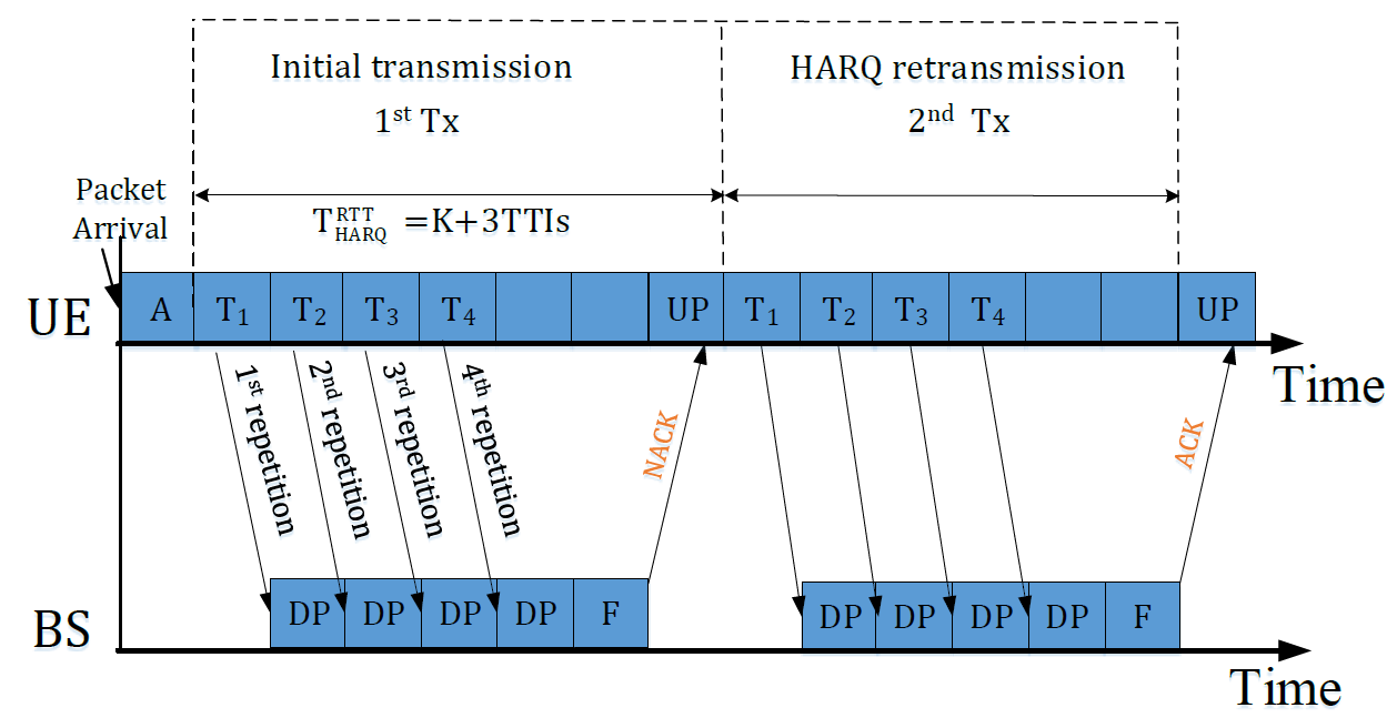
The Reactive scheme is illustrated in Fig. 2. After the UE finalizes its initial uplink transmissions (T), its signal will be processed at the BS (DP) for a HARQ feedback (F) (ACK/NACK). After processing the HARQ feedback (UP), the UE retransmits the same packet upon reception of a NACK. In this scheme, we note that the HARQ round trip time
| (2) |
Then the latency after HARQ round trips is obtained as
| (3) |
II-C2 K-repetition scheme
The K-repetition scheme is illustrated in Fig. 3, where the UE is configured to autonomously transmit the same packet for repetitions in consecutive TTIs. At the end of repetitions, the BS needs to combine the received repetitions, process the received packet, and feedback to the UE. In this scheme, the HARQ round trip time
| (4) |
Then the latency after HARQ round trips is defined as
| (5) |
II-C3 Proactive scheme
The Proactive scheme is illustrated in Fig. 4. Similarly to the K-repetition scheme, the UE is configured to repeat the transmission for a maximum number of repetitions but can receive the feedback after each repetition. This allows the UE to terminate repetitions earlier once receiving the positive feedback (ACK). We note that the UE could receive the 1st feedback 3TTIs after the 1st repetition.

That is to say, the minimum HARQ round trip time is 4. For , the UE continues repetitions until maximum . For , the UE continues repetitions until either the UE receives ACK from the BS, or the number of repetitions reaches maximum times[30]. Let us denote the 1st access success of the typical UE occurs in the th repetition during one HARQ round trip. Thus, we have the single HARQ round trip time for the Proactive scheme as:
| (6) |
Note that if , i.e., all the repetitions in one HARQ round trip are not successful with , the UE will perform HARQ retransmission in next round trip. Thus, the latency after HARQ round trips for the Proactive scheme with a maximum repetitions can be derived as
| (7) |
where I denotes that the transmissions in all the former () HARQ round trips are not successful; and II implies the possible case in the final th HARQ round trip given in (6).
II-D Signal to Noise plus Interference Ratio (SINR)
Note that the GF access failure occurs due to the following two reasons: 1) a pilot cannot be recognized by the received BS, due to its lower received SINR than the SINR threshold ; 2) the BS successfully receives two or more same pilots simultaneously, such that the collision occurs, and the BS cannot decode any collided pilots. Our model follows the assumption of collision model in [26][31], where all these collision UEs would not be decoded at the BS. Different from the data transmission with no intra-cell interference due to orthogonal resource allocation, the GF access analysis in this work needs to take into account both the inter- and intra-cell interference33 3 We consider intra-cell interference because the UEs in the same cell associated with the same BS may choose the same pilot. We consider the inter-cell interference due to that the UEs in different cells share the preamble sequence pool among BSs. Similar with [32], we focus on providing a general analytical framework of cellular network, considering both the inter- and intra-interference.. We formulate the SINR of a typical BS located at the origin as
| (8) |
where is the full path-loss inversion power control threshold, is the channel power gain from the typical UE to its associated BS, is the noise power, and are the aggregate intra-cell and inter-cell interference, which will be discussed in detail in Section III, and denotes the power level unit in the th retransmission by adjusting the target received power at the BS equal to [26][33] (i.e., ). Note that is the maximum allowable power level unit.
II-E Problem Formulation and Objectives
The URLLC requirement of the UL GF transmission is that the UEs can successfully complete their payload delivery within a limited time, i.e., , with a failure probability lower than a certain target, i.e., . For its performance characterization, we define the latent access failure probability as . To address this inherent limitation of URLLC requirements, it is meaningful to consider a probabilistic Quality of Service (QoS) in the following form:
Definition 1.
(URLLC QoS). We say the URLLC QoS of the UE is satisfied in a given frame if:
| (9) |
In 5G specification, and ms for general URLLC requirement[1].
III Performance Analysis and Evaluation
This section presents a general analytical model for three different GF HARQ schemes. We perform the analysis on a randomly chosen active UE in terms of the latent access failure probability under different latency constraints for three different GF schemes, respectively, in the following.
III-A Reactive scheme
In the Reactive scheme as illustrated in Fig. 2, the latent access failure probability remains unchanged at the beginning of each HARQ round trip and only changes at the end of each HARQ round trip (i.e., after processing the feedback at the UE in the 4th TTI of this round trip), as the UE needs time to transmit packet and receive feedback. For example, in one HARQ round trip (e.g., the th round trip), for TTIs, the latent access failure probabilities are the same as , since the UE can not receive feedback on time; for TTIs, the latent access failure probability changes determined by the UE’s retransmission or not after receiving NACK or ACK, respectively.
In order to calculate the latent access failure probabilities under various latency constraints, we need to know the maximum number of HARQ round trips allowed under the latency constraint TTIs. For ease of presentation, we define
| (10) |
with TTIs given in (2).
Note that inactive UEs (with empty data buffer) do not transmit, such that they do not generate interference. A UE is still active in the th () round trip if none of its GF access in the last () round trips are successful. Mathematically, the active probability of the UE in the th round trip, is obtained as
| (11) |
with obtained from (II-C1).
Based on (11), the latent access failure probability of a randomly chosen UE with the Reactive scheme is derived in the following Theorem 1.
Theorem 1.
The latent access failure probability of a randomly chosen UE with the Reactive HARQ scheme under the latency constraint is derived as
| (12) |
where is given in (10), is given according to (11) as
| (13) |
and is the GF access success probability of the typical UE in the th round trip with the Reactive scheme that derived in (14) of the following Lemma 1.
Proof.
See Appendix A ∎
Lemma 1.
The GF access success probability of the typical UE in the th round trip with the Reactive scheme is given by
| (14) |
where
| (15) |
and
| (16) |
Part I is the probability of the number of intra-cell interfering UEs for a typical BS 44 4 Note that means there are number of intra-cell interfering UEs (without the typicals UE), i.e., number of active UEs in one cell. derived following [34, Eq.(3)], where c = 3.575 is a constant related to the approximate PMF of the PPP Voronoi cell and is the gamma function. Part II is the transmission success probability of the UE conditioning on . Part III is the transmission failure probability that the transmissions from other intra-cell interfering UEs are not successfully received by the BS, i.e., the non-collision probability of the UE.
Proof.
See Appendix B. ∎
Remark 1.
In (1), it can be shown that the transmission success probability (II in (14)) of the typical UE is inversely proportional to the received SINR threshold and the density ratio . The transmission failure probabilities of other interfering UEs (III in (14)) (i.e, the non-collision probability of the typical UE) are directly proportional to the received SINR threshold and the density ratio . Therefore, a tradeoff between transmission success probability and non-collision probability is observed.
III-B K-repetition scheme
In the K-repetition scheme as illustrated in Fig. 3, the latent access failure probability also changes at the end of each HARQ round trip similar to the Reactive scheme, but with longer round trip time TTIs given in (4). More specifically, in one HARQ round trip (e.g., the th round trip) of the K-repetition scheme, for TTIs, the latent access failure probabilities are the same as ; for TTIs, the latent access failure probabilities changes determined by the UE’s retransmission or not after receiving NACK or ACK, respectively. Let us define
| (17) |
to imply the maximum number of HARQ round trips allowed under the latency constraint TTIs with TTIs, we can derive the latent access failure probability of a randomly chosen UE with the K-repetition scheme in the following Theorem 2.
Theorem 2.
The latent access failure probability of a randomly chosen UE with the K-repetition scheme under latency constraint TTIs is derived as
| (18) |
where is given in (17), is obtained according to (11) as
| (19) |
and is the GF access success probability of the typical UE in the th round trip with the K-repetition scheme that derived in (2) of the following Lemma 2.
Lemma 2.
The GF access success probability of the typical UE in the th HARQ round trip with the K-repetition scheme is derived as
| (20) |
where
| (21) |
and
| (24) |
Similar to Lemma 1., Part I is the probability of the number of intra-cell interfering UEs . Part II is the transmission success probability of the UE conditioning on . Part III is the non-collision probability of the UE.
Proof.
See Appendix C. ∎
Remark 2.
It is evident from (2) that the transmission success probability (II in (2)) of the typical UE increases, whereas the non-collision probability (III in (2)) decreases with increasing the repetition value . Therefore, there exists a tradeoff between transmission success probability and non-collision probability. For illustration, the relationship among GF access success probability , the transmission success probability with III=1), and the non-collision probability with II=1) versus repetition values are shown in Fig. 5. We can see that in certain scenario in (b) (i.e., dB and ), the increase of repetition value could not further improve, and even degrades the GF access success probability. This is due to the fact that increasing the repetition increases the collisions in overloaded traffic scenario, and wastes extra time and frequency resource. Further details will be described later in Section V.
Finally, the latent access failure probabilities under arbitrary latency constraints of a randomly chosen UE with the K-repetition and Reactive schemes can be derived based on the iteration process. Note that the Reactive scheme is a special case of K-repetition scheme when the repetition value .

We assume is a variable that denotes the HARQ round trip from 1 to . The iteration process for calculating the latent access failure probability is shown in Fig. 6. Details of this process are described by the following:
- •
Step 1: Calculate the maximum number of HARQ round trips under the given latency constraint TTIs using (17).
- •
Step 2: If , , otherwise go to Step 3;
- •
Step 3: Calculate the active probability in the th HARQ round trip using (19);
- •
Step 4: Calculate the GF access success probability in the th round trip using (2);
- •
Step 5: Calculate the latent access failure probability in the th round trip using (18).
Repeating Step 3 to 5 until , the latent access failure probability under latency constraint can be obtained.
III-C Proactive scheme
The analytical model for the Proactive scheme is more complicated compared with the Reactive and K-repetition schemes. In the former two schemes, the latent access failure probabilities only change at the end of each HARQ round trip, as the BS processes the received signal and sends the feedback to the UE once in each round trip. However, in the Proactive scheme, the latent access failure probabilities change at several TTIs in one round trip, as the BS processes each repetition and sends the feedback to the UE at several TTIs. Due to the complexity of the Proactive scheme, we first analyze the latent access failure probability of a randomly chosen UE with the latency constraint TTIs without HARQ retransmissions.
III-C1 Proactive scheme without HARQ retransmissions, TTIs
Compared with the K-repetition scheme, in which the UE is enforced to perform repetitions no matter if its transmission is successful or not within times, the UE in the Proactive scheme is allowed to terminate the repetition once the UE receives ACK. Take one example, as shown in Fig. 7, the UE-1 successfully transmits the packet in the 1st repetition, the UE-1 knows the success of its 1st repetition in the 4th repetition, and the UE-1 terminates its 5th repetition. That is to say, if a UE does not have a second packet to be transmitted, the Proactive scheme could help to reduce its interference to other UE(s) that share the same resource and happen to be active at the same time.

Due to the fact that the ACK/NACK feedback can only be received after 3TTIs, for the maximum repetition value , the UE can not receive feedback before completing repetitions, thus the UE needs to complete all the repetitions without terminating earlier and the number of interfering users will not change in each repetition of one round trip.
For , the UE can receive feedback from the BS to determine retransmission or not. For instance, the ACK feedback decreases the number of interfering users in the later repetitions as shown in Fig. 7. Let us denote that the st successful transmission occurs in the th repetition, thus the feedback of this repetition will be received in the ()th repetition, which affects the latent access failure probability of the UE in the ()th repetition, and from the ()th repetition, these successful UEs will not repeat the rest () repetitions for this packet any more.
We define the feedback factor for the th () repetition as , which means the GF access failure probability in the former () repetitions55 5 Note that the ACK/NACK feedback can only be received after 3TTIs, thus the feedback from the former () repetitions will affect the th repetition. Only the failure UEs in the former () repetitions will transmit in the th repetition.. It is obvious that when . Then we derive the feedback factor as
| (25) |
where is derived in the following Lemma 3.
Lemma 3.
We define the transmission success probability in the th repetition as , the transmission success probability in all repetitions as (i.e., any one of the repetitions succeeds ()), and the access success probability in repetitions as (considering collision). Then, the GF access success probability of a randomly chosen UE with the Proactive scheme under the latency constraint TTIs is driven as
| (26) |
where
| (27) |
and for ,
| (28) | ||||
| (31) |
and for ,
| (32) |
with
| (33) |
Proof.
See Appendix D. ∎
In order to calculate the latent access failure probabilities under arbitrary latency constraints TTIs, we define two indexes for as
| (34) |
where is given in (6)66 6 In the Proactive scheme with HARQ round trips, a UE is still active in the th () HARQ round trip if none of its GF access in the former () HARQ round trips is successful. That is to say, all the maximum repetitions in the Proactive scheme in the former () HARQ round trips are not successful, i.e., ., implies the maximum number of the HARQ round trips under the latency constraint (for the Proactive scheme under the latency constraint , ), implies the updated TTI index for the latent access failure probability in each HARQ round trip.
Then, the latent access failure probability of a randomly chosen UE with the Proactive scheme under the latency constraint is derived in Theorem 3.
Theorem 3.
The latent access failure probability of a randomly chosen UE with the Proactive scheme under the latency constraint TTIs is derived as
| (35) |
where is obtained from (26) of Lemma 3.
Next, we extend the analysis of the latent access failure probabilities of the typical UE with the Proactive scheme to an arbitrary latency constraint allowing the maximum number of HARQ round trips.
III-C2 Proactive scheme with HARQ retransmissions
In the Proactive scheme with HARQ retransmissions, a UE is still active in the th () HARQ round trip if none of its GF access in the former () HARQ round trips are successful. That is to say, all the maximum repetitions in the Proactive scheme in the former () HARQ round trips are not successful. Similar to the other two schemes, we give the active probability in the th HARQ round trip in (37). For an arbitrary latency constraint TTIs, we first obtain the two indexes and using (34), i.e., the maximum number of the HARQ round trips under the latency constraint is . Then, the latent access failure probability can be obtained in the following Theorem 4.
Theorem 4.
The latent access failure probability of a randomly chosen UE with the Proactive HARQ scheme under arbitrary latency constraint TTIs is derived as
| (36) |
where is obtained according to (11) as
| (37) |
and is the GF access probability of a typical UE in the th HARQ round trip, given in the following Lemma 4.
Lemma 4.
Finally, the latent access failure probabilities for the Proactive scheme under an arbitrary latency constraint can be obtained using the iteration process shown in Fig. 8 with the details described in the following.
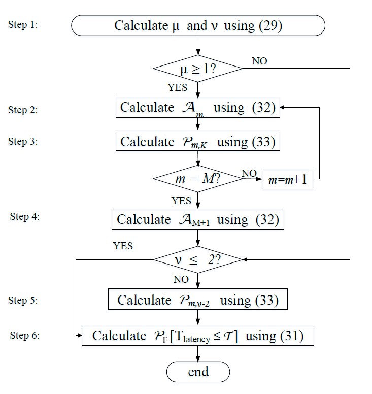
- •
Step 1: Calculate the indexes and under the given latency constraint TTIs usinig (34). If , go to Step 2; If , , go to Step 6; If , , go to Step 5;
- •
Step 2: Calculate non-empty probability using (37);
- •
Step 3: Calculate the GF access success probability in the th round trip, using (38);
Repeating Step 2 to 3 until ;
- •
Step 4: Calculate non-empty probability using (37);
- •
Step 5: If , calculate the GF access success probability using (38);
- •
Step 6: Calculate the latent access failure probability using (4).
IV Simulation and Discussion
In this section, we verify our analytical results by comparing the theoretical GF latent access failure probabilities with the results from Monte-Carlo simulations, where the simulations are performed using the system model described in Section II in MATLAB. The BSs and UEs are deployed via independent HPPPs in a 1600 km2 circle area with each UE associated with its nearest BS. At the beginning of each round trip, UEs randomly move to new positions and the active ones randomly choose a pilot from pilots to transmit. The channel fading gains between the UEs and BSs are modeled by exponentially distributed random variables. The simulation parameters used for this study are in line with the main guidelines for 3GPP NR performance evaluations presented in [30] with mini-slots of 7 OFDM symbols for transmissions in short TTI (0.125ms) using 60 kHz SCS77 7 Mini-slot durations will depend on the SCS and on the number of OFDM symbols for a given SCS, adopted according to the type of deployment and carrier frequency. . To focus on the GF access in UL, we assume feedback in DL is error-free.88 8 According to Section II.C, a HARQ round-trip includes: 1) UL (UE to BS): the UE transmits the signal to the BS and the BS decodes the received signal; 2) DL (BS to UE): the BS sends an ACK/NACK feedback and the UE processes the feedback to decide whether to perform a retransmission in the next HARQ. This is to say, from the UE perspective, one HARQ round-trip is finished until the UE processes the feedback to know whether it is successful or not, which should consider both the transmission probability in UL and DL. In this paper, to focus on the GF access in UL, we assume feedback in DL is error-free. The analysis of the feedback with error probability can be extended following this work.. The simulation time is configured to collect at least samples to ensure a sufficient confidence level on the quantile. In all figures of this section, “Analytical” and “Simulation” are abbreviated as “Ana.” and “Sim.”, respectively. Unless otherwise stated, we consider BSs/km2, , dB, , dBm, , , the noise = −174+10log10(60000) = −126.2 dBm.
Fig. 9-Fig. 10 plot the GF latent access failure probabilities of the UE with the Reactive, K-repetition, and Proactive schemes versus SINR thresholds dB and dB, respectively. The analytical curves of the Reactive and K-repetition schemes are plotted following the flowchart in Fig. 6, and the analytical curves of the Proactive scheme are plotted following the flowchart in Fig. 8. The close match between the analytical curves and simulation points validates the accuracy of the developed spatio-temporal mathematical framework. The stair behaviour (i.e., the latent access failure probabilities stay unchanged for a period of time) is caused by the waiting time between each retransmission.
In Fig. 9, we first observe that the latent access failure probabilities follow ProaReacKrep under latency constraints ms (5TTIs). We also observe that the latent access failure probabilities follow ProaKrepReac under latency constraints ms ms (12TTIs). In this case, under shorter latency constraints TTIs, the Proactive scheme should be chosen. This is due to that the Proactive scheme could terminate earlier to reduce latency without waiting for repetitions, which satisfies the shorter latency constraints. But when the latency constraints get longer, the advantage of the Proactive scheme than the K-repetition scheme is not obvious but the advantage of the Proactive and K-repetition schemes than the Reactive scheme is obvious, i.e., ProaKrepReac, due to that the UE has enough time to finish the repetitions and get feedback. We note that increasing repetition value increases the GF access success probability, as it offers more opportunities to retransmit. However, when the repetition value is too large (e.g., ), the latent access failure probabilities are not lower than those of the 4-repetition scheme in most of the time (except , ). This is due to that transmitting 8 repetitions will cost too much waiting time and introduce a much longer delay. It is obvious that if the repetition value is overestimated, the K-repetition scheme will waste the potential resource and lead to lower resource efficiency.
In Fig. 10, we first observe that latent access failure probabilities follow KrepReacProa, under longer latency constraints ms (12 TTIs) for small repetition value . In this case, under longer latency constraints TTIs, the K-repetition scheme should be chosen. We also observe that the 8-repetition scheme has the highest latent access failure probabilities. This is due to that there is a trade-off between transmission success probability and non-collision probability when increasing the repetition value, which is in line with Fig. 5 (b). Thus, in Fig. 10, increasing the repetition value to 8 does not decrease but increases the latent access failure probabilities because it introduces longer waiting time without increasing the access success probabilities. In this case, when the repetition value is overestimated, the Proactive scheme should be chosen.


Fig. 11-Fig. 12 plot the GF latent access failure probabilities under the latency constraint ms (8 TTIs) and ms (12 TTIs) for different density ratios and SINR thresholds. We observe that the GF latent access failure probability increases with increasing density ratio which is due to the following two reasons: 1) increasing the number of UEs generating interference leads to lower received SINR at the BS; 2) increasing the number of UEs leads to higher probability of collision. We also observe that the GF latent access failure probabilities decreases with decreasing SINR threshold. This is due to the lower SINR threshold leading to higher access success probability.
In Fig. 11, we observe that the GF latent access failure probabilities decrease in light load scenario (e.g., ), while increases in high load scenario (e.g., ) with increasing the repetition value, which is in line with Fig. 5 (b). This is due to the fact that increasing the repetition increases the collisions in overloaded traffic scenario, and wastes extra time and frequency resource. We also note that, as the latency constraint ms (8 TTIs), so the 8-repetition scheme can not be adopted because its waiting time for the 1st transmission is more than 1ms. But the Proactive scheme with a maximum of 8 repetitions could have as good performance as the 4-repetition scheme.
In Fig. 12, we observe that the GF latent access failure probabilities decrease in higher SINR thresholds scenarios (e.g., dB), while increases in lower SINR thresholds scenarios (e.g., dB) with increasing the repetition value . Thus, despite the K-repetition scheme can cope with tight time constraints by allowing a number of consecutive repetitions in a short time, the interference due to the multiple repetitions is the major impacting factor and surpasses the benefits of the combining gain in lower SINR threshold and high density scenarios.

Fig. 13 plots the GF latent access failure probabilities of the UE under the Reactive, K-repetition, and Proactive schemes with PB. Interestingly, we observe that PB has greater improvement in the Reactive and K-repetition schemes than the Proactive scheme. For example, without PB, GF latent access failure probabilities of the UE under the K-repetition scheme are similar to those of the Proactive scheme, while with PB, the GF latent access failure probabilities of the UE under the K-repetition scheme is much lower than those of the Proactive scheme.
Fig. 14 plots the GF latent access failure probabilities under the latency constraint ms (8 TTIs) versus density ratios and SINR thresholds for larger UE densities. We observe that when the density ratios (UE densities) are particularly large (), no matter what schemes are taken, the GF access cannot be successful, that is, the network is very crowded. Thus, the number of active UEs that access to the network should be limited to some thresholds.
V Conclusion
In this paper, we developed a spatio-temporal mathematical model to analyze and compare the grant-free access latent access failure probabilities of a randomly chosen UE with three different GF HARQ schemes for URLLC requirements. We defined the latent access failure probability to characterize the URLLC performance. We proposed a tractable approach to derive and analyze the GF latent access failure probabilities of the UE under the Reactive, the K-repetition, and the Proactive schemes, respectively. Our results have shown that 1) either K-repetition scheme or Proactive scheme provides lower latent access failure probability than the Reactive scheme, except higher density and lower SINR threshold scenarios; 2) under shorter latency constraints (TTIs), the Proactive scheme provides the lowest latent access failure probability; 3) under longer latency constraints, the K-repetition scheme provides the lowest latent access failure probability, which depends on , i.e., need to be optimized; 4) if is overestimated; the Proactive scheme provides lower latent access failure probability than the K-repetition scheme; 5) the Power Boosting can improve the latent access failure probability, especially for the K-repetition scheme (including =1). The analytical model presented in this paper can also be applied for the reliability and latency performance evaluation of other types of GF HARQ schemes in the cellular-based networks.
Appendix A A Proof of Theorem 1
For a given latency constraint TTIs, we have . For , the latent access failure probability is the probability that the UE fails to access in the 1st HARQ round trip, where we can derive
| (A.1) |
For , the latent access failure probability is the probability that the UE fails to access in neither two HARQ round trips, where we can derive
| (A.2) |
Substituting (11) into (A.2), we have
| (A.3) |
For , the latent access failure probability means the probability that the UE fails to access after all the three HARQ round trips. So we can derive
| (A.4) |
For , the latent access failure probability can be derived based on the iteration process following and .
Appendix B A Proof of Lemma 1
We derive the GF transmission success probability conditioning on number of intra-cell interfering UEs based on the SINR outage as
| (B.1) | ||||
The Laplace Transform of aggregate intra-cell interference conditioning on is derived as
| (B.2) |
where .
The Laplace Transform of aggregate inter-cell interference received at the BS is derived as
| (B.3) |
where (a) is obtained by taking the average with respect to , (b) follows from the probability generation functional (PGFL) of the PPP, (c) follows by changing the variables and is the moments of the transmit power. Substituting Eq. (B.2) and Eq. (B) into (B), we derive the transmission success probability in the th round trip as
| (B.4) |
We consider a general fading with the path loss exponent to simplify our results as
| (B.5) |
Appendix C A Proof of Lemma 2
For the K-repetition scheme, the GF transmission in one HARQ round trip is successful if any of the repetition succeeds. We derive the GF transmission success probability under repetitions conditioning on number of intra-cell interfering UEs based on the SINR outage as
| (C.1) |
Based on the Binomial theorem, (C) can be rewritten as
| (C.4) |
where is the binomial coefficient and
| (C.5) |
The Laplace Transform of aggregate intra-cell interference conditioning on is derived as
| (C.6) |
where .
Appendix D A Proof of Lemma 3
For , the UE can not receive feedback, thus the number of interfering users remains unchanged in each repetition. So we have
| (D.1) |
where
| (D.2) |
For , the UE can receive feedback from the 4th repetition, thus the number of interfering users changes from the 5th repetition. So we have
| (D.3) |
where
| (D.4) |
with
| (D.5) |
References
- [1] “Study on scenarios and requirements for next generation access technologies,” 3GPP, TS 38.913 v15.2.0, Jun. 2018.
- [2] M. Series, “IMT vision-framework and overall objectives of the future development of IMT for 2020 and beyond,” Recommendation ITU, pp. 2083–0, Sep. 2015.
- [3] B. Holfeld, D. Wieruch, T. Wirth, L. Thiele, S. A. Ashraf, J. Huschke, I. Aktas, and J. Ansari, “Wireless communication for factory automation: an opportunity for LTE and 5G systems,” IEEE Commun. Mag., vol. 54, no. 6, pp. 36–43, Jun. 2016.
- [4] C. Campolo, A. Molinaro, A. Iera, and F. Menichella, “5G network slicing for vehicle-to-everything services,” IEEE Wireless Commun., vol. 24, no. 6, pp. 38–45, Dec. 2017.
- [5] A. Azari, M. Ozger, and C. Cavdar, “Risk-aware resource allocation for URLLC: Challenges and strategies with machine learning,” IEEE Commun. Mag., vol. 57, no. 3, pp. 42–48, Mar. 2019.
- [6] M. Yao, M. Sohul, V. Marojevic, and J. H. Reed, “Artificial intelligence defined 5G radio access networks,” IEEE Commun. Mag., vol. 57, no. 3, pp. 14–20, Mar. 2019.
- [7] “5G; service requirements for the 5G system,” 3GPP, TS 22.261 v17.2.0,, Mar. 2020.
- [8] “Evolved universal terrestrial radio access (E-UTRA); physical layer procedures,” 3GPP, TS 36.213 V14.2.0, Mar. 2017.
- [9] “Semi-persistent scheduling for 5G new radio URLLC,” R1-167309, 3GPP TSG-RAN WG1 86, Aug. 2016.
- [10] “Dynamic scheduling based transmission for URLLC,” R1-1705245, 3GPP TSG-RAN WG1 88, Apr. 2017.
- [11] “UL grant-free transmission for URLLC,” R1-1705654, 3GPP TSG-RAN WG1 88, Apr. 2017.
- [12] L. Vangelista and M. Centenaro, “Performance evaluation of HARQ schemes for the internet of things,” Computers, vol. 7, no. 4, p. 48, Jul. 2018.
- [13] S. Sesia, I. I. Toufik, and M. Baker, LTE-the UMTS long term evolution: from theory to practice. John Wiley and Sons, 2011.
- [14] “5G; NR; physical layer procedures for data,” 3GPP TS 38.214 v15.9.0, Mar. 2020.
- [15] “ UL grant-free transmission for URLLC,” R1-1705246, Apr. 2017.
- [16] “Discussion on HARQ support for URLLC,” R1-1612246, 3GPP TR-RAN1 #87, Nov. 2016.
- [17] “Discussion on explicit HARQ-ACK feedback for configured grant transmission,” R1-1903079, 3GPP TSG RAN WG1 96, Mar. 2019.
- [18] N. Jiang, Y. Deng, X. Kang, and A. Nallanathan, “Random access analysis for massive IoT networks under a new spatio-temporal model: A stochastic geometry approach,” IEEE Trans. Commun., pp. 1–1, Jul. 2018.
- [19] R. Abreu, T. Jacobsen, G. Berardinelli, K. Pedersen, I. Z. Kovács, and P. Mogensen, “Power control optimization for uplink grant-free URLLC,” in 2018 IEEE Wireless Commun. Netw. Conf. (WCNC), Apr. 2018, pp. 1–6.
- [20] N. H. Mahmood, R. Abreu, R. Böhnke, M. Schubert, G. Berardinelli, and T. H. Jacobsen, “Uplink grant-free access solutions for URLLC services in 5G new radio,” in 2019 16th Inter. Symposium Wireless Commun. Systems (ISWCS), Aug. 2019, pp. 607–612.
- [21] K. I. Pedersen, G. Berardinelli, F. Frederiksen, P. Mogensen, and A. Szufarska, “A flexible 5G frame structure design for frequency-division duplex cases,” IEEE Commun. Mag., vol. 54, no. 3, pp. 53–59, Mar. 2016.
- [22] “RAN1 chairman’s notes,” 3GPP, TSG RAN WG1 NR Ad-Hoc2, Jun. 2017.
- [23] “Study on physical layer enhancements for NR ultra-reliable and low latency case (URLLC),” 3GPP, TR 38.824 v16.0.0, Mar. 2019.
- [24] R. Abbas, M. Shirvanimoghaddam, Y. Li, and B. Vucetic, “A novel analytical framework for massive grant-free NOMA,” IEEE Trans. Commun., vol. 67, no. 3, pp. 2436–2449, Mar. 2019.
- [25] B. Singh, O. Tirkkonen, Z. Li, and M. A. Uusitalo, “Contention-based access for ultra-reliable low latency uplink transmissions,” IEEE Wireless Commun. Lett., vol. 7, no. 2, pp. 182–185, Apr. 2018.
- [26] N. Jiang, Y. Deng, A. Nallanathan, X. Kang, and T. Q. S. Quek, “Analyzing random access collisions in massive IoT networks,” IEEE Trans. Wireless Commun., vol. 17, no. 10, pp. 6853–6870, Oct. 2018.
- [27] J. F. C. Kingman, Poisson processes. Wiley Online Library, Jan. 1993.
- [28] N. H. Mahmood, A. Karimi, G. Berardinelli, K. I. Pedersen, and D. Laselva, “On the resource utilization of multi-connectivity transmission for URLLC services in 5G new radio,” in 2019 IEEE Wireless Commun. Netw. Conf. Workshop (WCNCW), Apr. 2019, pp. 1–6.
- [29] T. Jacobsen, R. Abreu, G. Berardinelli, K. Pedersen, I. Z. Kovacs, and P. Mogensen, “System level analysis of K-repetition for uplink grant-free URLLC in 5G NR,” in European Wireless 2019; 25th European Wireless Conf., May. 2019, pp. 1–5.
- [30] “Study on new radio access technology-physical layer aspects,” 3GPP, TR 38.802 v14.0.0, Mar. 2017.
- [31] “Study on RAN improvements for machine-type communications,” 3GPP TR 37.868 v.11.2.0, Sept. 2011.
- [32] M. Gharbieh, H. ElSawy, A. Bader, and M. Alouini, “Spatiotemporal stochastic modeling of IoT enabled cellular networks: Scalability and stability analysis,” IEEE Trans. on Commun., vol. 65, no. 8, pp. 3585–3600, Aug. 2017.
- [33] Y. Yang and T. P. Yum, “Analysis of power ramping schemes for UTRA-FDD random access channel,” IEEE Trans. Wireless Commun., vol. 4, no. 6, pp. 2688–2693, Nov. 2005.
- [34] S. M. Yu and S. L. Kim, “Downlink capacity and base station density in cellular networks,” in 11th Int. Symp. Model. Optim. Mobile Ad Hoc Wireless Netw. (WiOpt), May. 2013, pp. 119–124.