An optic to replace space and its application towards ultra-thin imaging systems
Abstract
Centuries of effort to improve imaging has focused on perfecting and combining lenses to obtain better optical performance and new functionalities. The arrival of nanotechnology has brought to this effort engineered surfaces called metalenses, which promise to make imaging devices more compact. However, unaddressed by this promise is the space between the lenses, which is crucial for image formation but takes up by far the most room in imaging systems. Here, we address this issue by presenting the concept of and experimentally demonstrating an optical ‘spaceplate’, an optic that effectively propagates light for a distance that can be considerably longer than the plate thickness. Such an optic would shrink future imaging systems, opening the possibility for ultra-thin monolithic cameras. More broadly, a spaceplate can be applied to miniaturize important devices that implicitly manipulate the spatial profile of light, for example, solar concentrators, collimators for light sources, integrated optical components, and spectrometers.
Introduction
Metasurfaces — engineered surfaces consisting of sub-wavelength scatterers — have attracted a great deal of attention for enabling flat optical components [1, 2, 3, 4, 5, 6]. These devices have been implemented in a diverse set of novel linear [7, 8, 9, 10, 11] and nonlinear optical [12, 13, 14] applications, including sub-wavelength-scale broadband achromatic lenses [15], the generation of various transverse spatial modes [1, 8], lasing [16, 17], polarimetry [18], and holograms [19], among others. Notably, metalenses are seen as the most promising by far due to their impact in miniaturizing imaging systems [20, 21]. However, in all imaging systems, lenses represent just one of the two main components; the other, sometimes overlooked in this context, is the millimeter-to-meter-scale optical propagation surrounding the lenses and separating them from the object and image. As evidenced by the long physical length of a typical (e.g., Galilean) telescope, the distances between lenses are just as critical to image formation as the lenses themselves, and can easily be greater than the summed thicknesses of the lenses by an order of magnitude. To date, no work has been published that addresses this dominant contribution to the size of many optical systems.
We present here a potential path towards replacing these distances with an optical element that we call a ‘spaceplate’. The functionality of a spaceplate is highlighted in Fig. 1a— this element would occupy a physical thickness of while propagating light for an effective length of , where the ratio between these two quantities is the compression factor of the plate. Some metamaterials, such as those based on transformation optics [22, 23], already feature the compression of electromagnetic fields (e.g., for field concentrators [24] or hyperlenses [25]). Though compression of propagation distance can be implicit in these works, this compression has not been an aim unto itself, particularly for reducing the length of imaging systems. There are many optical devices that implicitly use imaging (e.g., a grating spectrometer works by imaging a slit [26]) or that spatially manipulate light using its propagation, such as solar concentrators [27], multiplane mode demultiplexers [28], or multi-mode interferometers in integrated optics [29]. All of these devices could be shortened through use of a spaceplate, leading to significant practical advantages.

It is easiest to describe the operation of the spaceplate by way of example — to this end, we consider the use of a spaceplate in a camera, as illustrated in Fig. 1b. The space between the lens and the sensor of a camera is dictated to a large degree by the focal length of the lens. A relatively large focal length is necessary to suitably magnify an image, which leads to long lens-barrels in cameras. One approach towards reducing this length could be the use of a spaceplate, allowing for the large magnification of a faraway object without the need for a large propagation length. While nominally this is also the goal of a telephoto lens, in practice the length of a telephoto lens barrel has been approximately constrained to be 0.8 times its effective focal length [1] (See Sec. S2: S2 Comparison to a telephoto lens for more discussion). Unlike a telephoto lens, a spaceplate could therefore break the trade-off between lens-barrel length and image magnification. Moreover, since the resulting image may now be large, so can the image sensor (e.g., the charge-coupled device (CCD) array). One can capitalize on this larger sensor by using larger pixels for low-light sensitivity, or a greater number of pixels for a higher resolution. In this way, the spaceplate could one day break the trade-off between camera miniaturization and any of resolution, sensitivity, magnification, or field-of-view.
In this work, we develop the general concept and theory of the spaceplate, followed by the proposal of several physically realizable types of spaceplates. In particular, we introduce and fully simulate the operation of a proof-of-principle multilayer design (i.e., a ‘thin-film stack’). This 25-layer design consists of only two materials, barely utilizing the full potential of current fabrication capability, which reaches over a thousand layers of multiple different materials [31]. We follow this modelling by some experimental demonstrations of two other types of spaceplates, albeit ones with a modest compression factor. These experiments will establish that spaceplates can be polarization independent, exhibit broadband operation, or have a large numerical aperture; thus, in concept, spaceplates can satisfy all three of these performance targets. However, it remains to be shown that these targets are compatible with each other or with a usefully large compression factor and effective length . We conclude with some discussion and analysis of the further advances that are necessary for spaceplates to become practical devices.
Results
Fourier optics analysis of the operation of a spaceplate
To define the action of the spaceplate, we make use of Fourier optics [32]. Namely, we consider how free propagation transforms each plane-wave component of an incident field. Each plane-wave is a given transverse spatial Fourier component with momentum vector . The amplitude of each -vector component is preserved in its free-space propagation whereas its phase is shifted. Consider two points along separated by for a given plane-wave. The wave’s phase difference between these points will be , where , and is the angle of from the -axis. Combining this amplitude and phase behaviour, the Fourier transfer function of free space is . Free propagation will effectively multiply each incident plane-wave by this factor.
A spaceplate needs to produce the same transfer function. A transfer function with the -vector yields a propagation phase of , where is the wavelength of light in vacuum and is the index of the background medium (BG) in the slab of space. The critical action of a spaceplate is thus to produce an angle-dependent phase profile that is equal to , the phase from propagation through a distance of the background medium. However, the spaceplate must do so within a distance shorter than — in particular, in a plate thickness . Note that the angular phase profile possesses the following two properties. The first is that the addition of an arbitrary phase offset that is global (i.e., independent of ) will not affect the imaging properties of the system [21]. Second, the image will also not be affected if is discontinuous as a function of with discontinuities of an integer multiple of ; this type of solution would correspond to the Fourier-space analogue of a Fresnel lens [33, 34]. These two free parameters hint at the substantial flexibility available to design a spaceplate.
Such a momentum-dependent response, where an optical element acts on the phase or magnitude of the spatial Fourier components of a beam, has been called a ‘nonlocal’ response [35, 36, 37]. Specifically, an ideal spaceplate would impart the phase,
| (1) |
whereas its ‘local’ position-dependent counterpart is a positive, spherical, thin lens, [38]. Unlike a position-dependent response, a purely momentum-dependent response, such as the one in Eq. 1, cannot redistribute momentum components. That is, it cannot redirect the angle of a light-ray and, thus, it comes with no magnification and has no optical power (i.e., dioptric power), unlike curved mirrors or lenses. Therefore, a spaceplate is an optical element complementary to the lens.
Nonlocal response engineering has been a fruitful research direction baring applications such as angular pass-filtering [39], image processing [40, 41, 42, 43], and analog computing [36]. One previous work in nonlocal responses used a lens system similar to a 4f telescope to impart a -dependent phase and magnitude response [36]. However, the use of a lens and propagation to create a spaceplate defeats its purpose of replacing propagation. A metamaterial, on the other hand, has only ever been engineered to have an angle-dependent transmittance [36, 39, 40, 41, 42], thereby solely affecting the magnitude of the Fourier component. In contrast, we focus on materials that impart a phase to each Fourier component. In order to achieve this behaviour, we consider spaceplate designs that are translationally invariant along the transverse directions and . This invariance guarantees that a transmitted wave will have the same -vector as the incident wave, which is a necessity for unity transmittance, . By manipulating the momentum-dependent phase, the spaceplate is a first example along a new avenue in nonlocal metamaterials research.
A multilayer spaceplate design
Since nonlocal responses are based in momentum-space, and not in position-space such as with metasurfaces, it is at first glance not obvious whether a nonlocal response corresponding to a spaceplate may be realized in a physical system, or whether a realistic spaceplate would have any intrinsic trade-offs between its performance parameters. We now explore whether a spaceplate can be designed out of multilayer stack (Fig. 1e). Since this structure is made up of parallel flat layers of various materials, it possesses the transverse translational-invariance that we desire. Moreover, the production of these stacks is a mature technology, appearing in many consumer and industrial products, with commercial companies capable of fabricating sophisticated designs with thousands of layers of several different materials. Consequently, such stacks can incorporate considerable complexity and design freedom. In Ref. [36], multilayer stacks were theoretically considered for general nonlocal responses, and a structure was designed that, in modelling, modulated the momentum-dependent transmittance magnitude. Instead, we design a stack to impart the momentum-dependent phase that we require for a spaceplate (where is greater than , the total stack thickness). The purpose of this design is simply to establish that a multilayer architecture can produce a spaceplate and also to determine some initial performance characteristics.

Since a deterministic and analytic design method for general multilayer stacks has yet to be invented, we use an optimization-based design method, as in Ref. [36]. In particular, we use a genetic algorithm targeting that maximizes the compression factor . To set a realistic but relevant goal, we aim only to produce this phase response for a numerical aperture that matches that of modern smartphone cameras, that is, out to an incident angle of , i.e., NA = 0.26 (Fig. 2a). Similarly, in order to aim for an easily fabricated design, we restrict the algorithm to two common materials, silica and silicon. This restriction is in contrast to the work in Ref. [36], where they employed permittivities of arbitrary values idealized to be lossless. We limited our structure to a total thickness of approximately 10 1 0 -.15 1m and a maximum of 40 layers so that the algorithm could comfortably run on a standard personal computer. The algorithm took four hours to yield a 1 0 -.15 1m-thick, 25-layer structure. It acts as a spaceplate with a compression factor of for vacuum-filled space () for 1550 nm wavelength light. (See Sec. S3: S3 Spaceplate metamaterial for more details on this structure.)
In order to test the performance of the designed multilayer structure, we use full-wave simulations to propagate a converging beam through the stack. Full-wave simulations have been validated in the literature to provide accurate predictions for linear optical responses in dielectric materials, such as the case here [44]. Consequently, we do not fabricate and experimentally test this structure, which, with its moderate value of , small , and low transmittance, is still far from being a useful device. Simulations of a focusing beam propagating in vacuum and in a spaceplate are shown in Fig. 2b – f. Analogous to in Fig. 1c – d, these show that this structure indeed advances the beam focus in vacuum towards the plate, as desired. Fig. 2g shows the advance is 1 0 -.15 1m, which corresponds to a compression factor of , in approximate agreement with the prediction. Thus, 10 1 0 -.15 1m of spaceplate metamaterial may be used to replace propagation through over 50 1 0 -.15 1m of the background medium, here, vacuum. Though these properties were not explicitly requested by our optimization algorithm, our simulations show that this device design is both polarization-insensitive and advances the focus for a bandwidth spanning 30 nm. (See Sec. S3: S3 Spaceplate metamaterial for more details on the performance of this structure.) Crucially, the compression factor of this structure exceeds the ratio of any of the indices in the spaceplate (, , ) and, thereby, demonstrates that this ratio does not impose a fundamental limit on . While here we aimed to replace vacuum, in order to achieve a higher numerical aperture for an imaging system, one could instead design the multilayer structure to replace a higher-index background medium since . The success of the relatively simple structure we designed hints at the promise of more complicated multilayer stacks for creating spaceplates with large compression factors.

Homogeneous media as a spaceplate
A drawback of multilayer stacks is the need for an optimization-based design method, which provides little physical insight into the limitations and operating mechanisms of a spaceplate. For this reason, in this section, we instead consider the possibility of unstructured spaceplates, i.e., homogeneous media. The nonlocal phase response is created by allowing for an angle-dependent refractive index of the media , for which we solve to find
| (2) |
where is the -vector angle within the spaceplate medium and (see Sec. S4: S4 Homogeneous spaceplate solutions for details). Such a homogeneous non-isotropic plate acts as a spaceplate with compression factor for a background medium with refractive index .
We now discuss the requisite index profile in more detail and identify a physically realizable solution. From here on, we assume for all angles and take the positive root. Since the global phase offset is still arbitrary, so is . Thus, parametrizes an infinite family of solutions, some of which are shown in Fig. 1g. One realizable homogeneous solution is with (Fig. 1f). This solution is related to but is distinct from a solution from transformation optics that compresses the full electromagnetic field [22, 23, 45]. Other solutions are presented in Sec. S4.2: S4.2 Discussion of specific solutions. Remarkably, we find that the refractive index described by this solution is that of a negative uniaxial birefringent medium ( for ordinary (o) and extraordinary (e) polarizations) with and its e-axis along (see Sec. S4: S4 Homogeneous spaceplate solutions for details). A light field with e-polarization propagating through this medium experiences a compression factor along of relative to propagation in isotropic medium . Theoretically, this negative uniaxial medium acts as a perfect spaceplate for all incident angles.
In order to show conclusively that the spaceplate concept does work in practice and to explore its limitations, we experimentally test this uniaxial spaceplate. (We present tests of a second type of homogeneous spaceplate, a low-index medium, in Sec. S5: S5 Low-index spaceplate measurements.) Naturally available uniaxial crystals have and so, instead of comparing to propagation in vacuum, we are limited to comparing to a background medium with , here linseed oil (). We use a -mm-long calcite crystal (CaCO3) plate with its optic axis oriented perpendicular to its entrance and exit faces. With and , the resulting compression factor is a modest , far from being of practical use but sufficient for proof-of-principle tests. We propagate a focusing beam through the oil and compare it to the same beam when propagating through the uniaxial spaceplate placed in oil. An ideal spaceplate will shift this focus by . Looking at Fig. 3a, we see that the addition of the spaceplate clearly shifts the focus towards the plate. The measured shift for the e-polarized beam is mm, which agrees well with the predicted shift of mm (see Sec. S6: S6 Polarization measurements for details on the o-polarized beam). The spaceplate advances the focus of a beam, just as if it had passed through an additional length of the background medium, thereby showing that the theoretical concept works in practice.
We next experimentally investigate the transverse displacement of a beam incident on a uniaxial spaceplate. This effect is central to the spaceplate’s application since it also applies to rays in the standard ray-tracing-based design of lens systems. In order to test whether a uniaxial spaceplate is inherently limited in numerical aperture, we vary the angle of incidence of the beam with respect to the normal of the calcite interface. For each angle, we record the beam’s lateral displacement (indicated by in Fig. 1a) upon exiting, shown in Fig. 3b. The observed displacement (red data) is equal to the ideal displacement of a beam travelling through of the linseed oil at angle (dashed theory curve). Consequently, the uniaxial is found to perfectly reproduce the free-propagation displacement for all measured angles, i.e., up to , corresponding to in oil.

Recently introduced exotic optical material responses, such as negative or near-zero epsilon, have sometimes been associated with material resonances that limit the bandwidth of corresponding devices [4]. To probe whether space compression is an inherently narrowband phenomenon, we test the capability of a spaceplate to reduce the size of a complete full-spectrum visible imaging system. A print of the painting in Fig. 4a is illuminated using an incoherent visible white-light source. A lens system forms an in-focus image of the print at an image plane inside a tank of glycerol placed after the last lens (Fig. 4b). While glycerol ( ) matches slightly worse than linseed oil, it has a higher transmittivity across the visible spectrum, which makes it more suitable for full-colour imaging. (See Sec. S1: S1 Experimental Setup). Figure 4c shows images captured by a CCD camera at a series of different positions along the system axis (see Sec. S7: S7 Movies). At , Fig. 4c shows that the captured image is in sharp focus, whereas at position mm, the captured image is still out of focus, as it has not propagated far enough to fully form. We now look at how the spaceplate affects this image formation by placing the calcite crystal into the glycerol before the image plane. The bottom row of Fig. 4c shows the images captured at the same positions as the top row, now with the spaceplate in place. Now, the image comes into focus sooner than with the glycerol alone. Specifically, the captured image is sharp at position mm, whereas in the top row, the image is still forming. Thus, we observe an image advance of mm, in approximate agreement with the theoretical prediction of mm. The entire color image remains in focus simultaneously, illustrating the broadband operation of the uniaxial spaceplate. Furthermore, the magnification of the image is preserved, as evidenced by comparing the sizes of the images at their respective focal planes. Thus, the lens system has been shortened without changing the field of view, the NA, or the magnification. In contrast, shortening the lens system by reducing the lens focal lengths would change all three of these important imaging system parameters.
Discussion
We have introduced the concept of the spaceplate and presented two types, which we have simulated and experimentally tested in order to address select potential inherent limitations. The uniaxial spaceplate (and the low-index spaceplate, see Sec. S5: S5 Low-index spaceplate measurements) experiments unambiguously demonstrate that a spaceplate is something physically realizable, validating our predictions and Eq. 2. The uniaxial spaceplate experiments, in particular, also show that a spaceplate can be simultaneously broadband in the visible regime, achromatic, have a high NA, as well as high transmission-efficiency, albeit for a small compression factor (). The metamaterial and low-index spaceplate show that a spaceplate may be polarization-independent. Furthermore, the metamaterial spaceplate shows that a spaceplate may have a compression factor that is many times larger than unity () and not bounded by the ratio of the indices of any of its constituent materials. It remains to be established whether these properties could be combined in a single spaceplate design that has a usefully large compression factor , similar to what has been accomplished over the last decade in metalenses [1, 47, 38, 48, 15, 49, 50].
In order to gauge the amount of spaceplate improvement that is yet required, we estimate some performance parameters for a few potential applications. We will assume the use of a multilayer spaceplate and, thus, a total thickness of 100 1 0 -.15 1m, the limit of current thin-film coating technology. The first application is inside a modern smartphone camera, which contains typical spacings of to mm. A corresponding of 10 to 40, only a factor of two to eight more than what we have presented, would compress these distances to 1 0 -.15 1m, inconsequentially small for a camera. Such a spaceplate would need to operate over the full visible wavelength range, have an NA of 0.2, and be polarization insensitive. All of these properties have been demonstrated in the present work, albeit separately. Moreover, sequentially depositing such a spaceplate and a metalens on top of an image sensor would compress an entire camera into an ultra-thin monolithic form-factor. A second application is to shorten the to cm distance between the lens and display in virtual reality (VR) headsets. This distance has been identified by industry as a key obstacle to adoption [51]. An of 200 to 400 (for 1 0 -.15 1m) would effectively eliminate this distance. While the required NA is high (e.g., , but still below that of our uniaxial spaceplate), other requirements are relaxed. In particular, since liquid crystal displays emit only a single polarization and need only emit three narrowband colours (RGB, such as in laser-based displays), the spaceplate need only function correctly for a single polarization and three optical wavelengths. Lastly, in integrated optics, narrowband (i.e., single-wavelength, 1550 nm) single-polarization devices are common [29, 52]. Such a spaceplate, with a modest compression factor of , similar to our multilayer design, would significantly increase the density of devices on a chip. Although improvement in spaceplate performance will be necessary, the requirements of these potential applications suggest that these advances are not so large as to be implausible.
We now consider whether and by what means the compression ratio could be improved. As our metamaterial design is based on optimization methods, it cannot directly inform us on whether or not fundamental physics may impose limits on . However, causality does not seem likely to constraint since the overall time delay for the imaging light to pass through the spaceplate is unconstrained (see Sec. S8: S8 Implications of causality for further discussion). Moreover, temporal effects, such as frequency chirp, are free to occur since they are irrelevant to imaging, which is a quasi-static process. Therefore, we do not foresee any fundamental limits to ; however, there may exist fundamental trade-offs between and other performance parameters (e.g., operation bandwidth or numerical aperture). Establishing the exact nature and subsequent consequences of these potential trade-offs is a topic for future work.
We propose the following avenues by which the compression factor could be increased. First, the feasibility of two of the homogeneous spaceplate solutions amongst the set given by Eq. 2 suggests that other solutions in the set may be physically realizable and might bear a higher (see Sec. S4.2: S4.2 Discussion of specific solutions for a discussion of other solutions). Second, industry has sophisticated design methods that could optimize a multilayer spaceplate made of a stack of thousands of layers of multiple materials, which might yield greatly higher values of . A third avenue is engineering an artificial uniaxial medium analogous to the calcite we used. For example, composite materials can be used to create record-breaking anisotropic responses [53]. Or, as another example, a uniaxial medium can be fabricated by alternating sub-wavelength-thick layers between two materials [54, 55, 56, 57]. The latter would create a uniaxial spaceplate with the potential advantages that the birefringence (and, hence, ) can be larger, broadband, and also slowly varied along to avoid reflection at the interfaces. By following these avenues and others, we expect spaceplates to rapidly improve.
From a broader perspective, the spaceplate further demonstrates the power of nonlocal optical elements that operate directly on the phase of transverse Fourier components of a light field. To the best of our knowledge, this work is the first to design a metamaterial that directly manipulates the phase in -space. Achieving full nonlocal control (e.g., combining the control of transmittance with phase control) would enable all of the benefits of Fourier optics (e.g., spatial filtering) without needing a lens system to access the farfield. In turn, repeatedly iterating between this momentum-dependent Fourier control and position-dependent control has been shown to enable fully arbitrary and lossless spatial-transformations of light fields [58]. Using nonlocal metamaterials and local metasurfaces to respectively accomplish these two controls opens the possibility of complete spatial control of light in a monolithic device.
Methods
Homogeneous spaceplates
Background medium:
The background medium for measurements in Fig. 3 is linseed oil (also known as flaxseed oil). This oil (refractive index at an optical wavelength of nm) was chosen to match to of the uniaxial spaceplate material (). The colour imaging measurements in Fig. 4 instead used a background medium of glycerol ( at 532 nm). While glycerol matches slightly worse than linseed oil, it has a higher transmittivity across the visible spectrum, which makes it appropriate for full-colour imaging.
Uniaxial spaceplate:
We use a 20.04 mm 19.98 mm 29.84 mm (width height depth, mm) right rectangular prism made of calcite that was cut with its extraordinary optical axis along the depth direction. The surfaces perpendicular to this axis are polished and used as the entrance and exit faces. Note that the surface quality is low, which somewhat distorts and scatters the beam in the measurements in Fig. 3 (see Sec. S9: S9 Fabricated spaceplates). Calcite is negative uniaxial with refractive indices , at a wavelength of nm. For e-polarized light in a background medium with , this crystal gives an expected enhancement factor of and an advance mm (i.e., a shift towards the crystal). The o-polarized light will experience a medium of isotropic refractive index . Consequently, and .
Low-index spaceplate:
Our implementation of a low-index spaceplate consists of a glass-faced cylindrical cell containing air (length mm and mm). The faces are mm thick microscope coverglass pieces (see Sec. S9: S9 Fabricated spaceplates).
Experimental setup
The experimental setup is shown in Fig. S1.
Light sources:
The measurements in Fig. 3 used a 4.5 mW diode laser with an optical wavelength of 532 nm. We spatially filter the laser beam with a single-mode fiber. The beam that is then focused to a waist of 1 0 -.15 1m ( radius) with a half-angle and a Rayleigh range of mm, all in the background oil medium. The measurements in Fig. 4 instead used incoherent visible white-light illumination.
Field relay system:
Both the beam measurements and imaging measurements use a field relay lens system to relay the full electric field profile to a region outside the tank containing the background medium and spaceplate. The mm lens after the tank and the mm lens are separated by a distance mm, which constitutes a common lens system known as a 4f system. The resulting magnification is . The system relays the field outside such that . Outside the tank, we use an image sensor (CCD) to record the intensity spatial-distribution in the plane. We then scan the CCD along . Five images are taken at each step and averaged to reduce camera noise. A shutter is closed in order to acquire background images, which are subtracted from the raw images to compensate for stray light and camera noise. For the measurements in Fig. 3, we use a monochromatic camera ( pixels, 2.4 1 0 -.15 1m 2.4 1 0 -.15 1m each, 12 bit). For the measurements in Fig. 4, we use a colour camera ( pixels, 5.86 1 0 -.15 1m 5.86 1 0 -.15 1m each, 12 bit). In the figures, we report the dimensions of the field inside the oil.
Beam measurements:
The beam measurement setup is shown in Fig. S1a. A diode laser produces a beam of wavelength 532 nm with a power of 4.5 mW. This beam is attenuated using a filter and then has its spatial mode filtered by a single-mode fiber. The beam exiting the fiber is collimated. A half-waveplate () and polarizing beamsplitter (PBS) are used to vary the beam intensity and polarize the beam. The beam’s polarization is subsequently controlled by a zero-order half-waveplate () and quarter-waveplate (). The lens before the tank, mm, is used to focus the beam through the spaceplate. The spaceplate’s entrance surface is located 80 mm from this lens. The tank contains linseed oil as a background medium. We then use the field relay system to image the transmitted beam. For the measurements in Fig. 3a, we move the camera along , recording an image at steps of 0.02 in (0.508 mm) over a range of 60 mm. For the measurements in Fig. 3b, the camera -position is set so that the camera images the beam focus. In order to measure the lateral beam displacement , the spaceplate is then tilted by an angle about in steps of over a range of and for the calcite and air plates, respectively (note that these ranges are the maximum allowed by the clear aperture of the respective spaceplate). For each camera position or crystal angle , the recorded image is summed along the -direction to arrive at an intensity distribution along . These intensity distributions are presented along the vertical direction of the plots in Fig. 3.
Imaging measurements:
The imaging measurement setup is shown in Fig. S1b. With visible white light, we illuminate a 15 mm 12 mm print of a painting (First Nations War Canoes in Alert Bay by Emily Carr, 1912) printed on ordinary white paper. At a distance mm from the print is a lens of focal length mm. A further mm from the lens is the first mm lens. Together this lens pair (NA) collects the the light reflected from the print, transmits the light through the spaceplate in the tank, which then forms in the background medium an image of the print with magnification . Between this lens pair is a linear film polarizer (visible broadband, nm), which we rotate to set the polarization of the light. The spaceplate is placed mm after this lens. The background medium in the tank is now glycerol rather than linseed oil since the former has a high transmission across the visible spectrum, which is ideal for full-colour imaging. We then use the field relay system to image the field after the spaceplate at various propagation distances . For the measurements in Fig. 4, we move the camera along , recording an image at steps of 0.02 in (0.508 mm) over a range of 100 mm. In the focused image plane, the image has dimensions of 6.25 mm 5.03 mm on the camera sensor.
Polarization control:
A uniaxial spaceplate acts to replace space for e-polarized light. However, the e-polarization direction varies depending on the angle of the incident wavevector relative to the crystal’s extraordinary optic axis. In order for the incident light field to be simultaneously e-polarized and approximately uniformly polarized along one direction, the crystal is tilted slightly about by an angle relative to the incident beam (and system axis). The tilt is for Fig. 3a and for Fig. 4. An -polarized light field will then be e-polarized with respect to the crystal; a -polarized field will be o-polarized. For the laser, the incident polarization is set by a polarizing beamsplitter followed by waveplates. The polarization of the white light is set by a film polarizer designed for broadband visible light. More generally, the uniaxial spaceplate works for a lightfield with an angularly non-uniform polarization that is extraordinary everywhere (e.g., a radially polarized field).
Coordinate system:
We use as a coordinate system for the experiment, where and are the transverse directions and is the optical system axis (i.e., the beam axis). The crystal’s height dimension is along . The extraordinary optical axis of the tilted crystal defines of a second coordinate system, . Thus, the second coordinate system is related to the first by a rotation about by angle . The uniaxial spaceplate always acts as distance along with . This tilt reduces the effective distance along by a factor , which for small is approximately unity.
Multilayer metamaterial spaceplate
Metamaterial structure:
We consider structures made up of planar layers alternating between two materials, silicon and silica (i.e., a ‘multilayer stack’). Each layer can have an arbitrary thickness larger than 10 nm, set by feasible fabrication capabilities. The combined thickness of the entire stack is designed to be approximately 10 1 0 -.15 1m.
Genetic algorithm:
Our aim is to design a multilayer stack to replace a background medium of vacuum. To do so, we search for a structure that gives a phase profile that matches the phase profile resulting from propagation through a slab of vacuum of length . We restrict this aim to a range of incident angle from zero to (i.e., the NA of the spaceplate). The search is conducted with a genetic algorithm whose goals are to maximize while minimizing any optical aberration resulting from a non-ideal phase profile. To quantify the latter goal, we first calculate the difference of the slope from that of the ideal profile, , where . This angular slope is the relevant quantity to consider since any global phase and phase wraps will be eliminated by the derivative. We then find the root-mean-square (RMS) of this difference, . The RMS deviation is an optical aberration that results in an increased beam waist relative to the waist in the absence of the multilayer stack. As a worst case scenario, this larger waist will increase the Rayleigh range to . The parameter increases with aberration and the inverse of the usable angle . The two goals of the algorithm can be combined in a single fitness function, , where we have used the small-angle approximation repeatedly. The larger the value of is, the better the performance of the multilayer spaceplate will be.
We now outline the functioning of the genetic algorithm. Each generation in the genetic algorithm had a population size of 500. The DNA of each population member was the material and the thickness of each layer in the stack. We used two materials, silica and silicon. The maximum number of layers was set to 40 and each layer was constrained to have a thickness greater than 10 nm. For each member, we use the standard transfer matrix formalism to calculate the complex transmission amplitude of the multilayer stack for a set of incident angles . We use nonlinear regression to fit with an ideal phase profile , giving and, with this fit, we numerically calculate . Both the fit and calculation are conducted over a range of input angles from zero to . With these performance parameters we find the fitness of each population member. The device thickness of the first generation is constrained to 10 1 0 -.15 1m, but this parameter is not constrained for later generations. The algorithm was carried out until there was a convergence in the fitness of the “best” member of each generation. For the structure reported here, this took 4000 generations.
Full-wave simulations:
The simulation in Fig. 2 was performed using a commercial 2D finite-difference time-domain solver. The boundary conditions are perfectly-matched layers. Exact details about the geometry of the structure and material parameters can be found in Sec. S3: S3 Spaceplate metamaterial.
References
- [1] Yu, N. et al. Light Propagation with Phase Discontinuities: Generalized Laws of Reflection and Refraction. Science 334, 333–337 (2011).
- [2] Kildishev, A. V., Boltasseva, A. & Shalaev, V. M. Planar photonics with metasurfaces. Science 339, 1232009 (2013).
- [3] Yu, N. & Capasso, F. Flat optics with designer metasurfaces. Nature Materials 13, 139–150 (2014).
- [4] Meinzer, N., Barnes, W. L. & Hooper, I. R. Plasmonic meta-atoms and metasurfaces. Nature Photonics 8, 889–898 (2014).
- [5] Chen, H.-T., Taylor, A. J. & Yu, N. A review of metasurfaces: physics and applications. Reports on Progress in Physics 79, 076401 (2016).
- [6] Genevet, P., Capasso, F., Aieta, F., Khorasaninejad, M. & Devlin, R. Recent advances in planar optics: from plasmonic to dielectric metasurfaces. Optica 4, 139–152 (2017).
- [7] Cui, Y., Kang, L., Lan, S., Rodrigues, S. P. & Cai, W. Giant chiral optical response from a twisted-arc metamaterial. Nano Letters 14, 1021–1025 (2014).
- [8] Karimi, E. et al. Generating optical orbital angular momentum at visible wavelengths using a plasmonic metasurface. Light: Science & Applications 3, e167 (2014).
- [9] Ni, X., Wong, Z. J., Mrejen, M., Wang, Y. & Zhang, X. An ultrathin invisibility skin cloak for visible light. Science 349, 1310–1314 (2015).
- [10] Arbabi, A., Arbabi, E., Horie, Y., Kamali, S. M. & Faraon, A. Planar metasurface retroreflector. Nature Photonics 11, 415–420 (2017).
- [11] Faraji-Dana, M. et al. Compact folded metasurface spectrometer. Nature Communications 9, 4196 (2018).
- [12] Yang, Y. et al. Nonlinear Fano-Resonant Dielectric Metasurfaces. Nano Letters 15, 7388–7393 (2015).
- [13] Li, G. et al. Continuous control of the nonlinearity phase for harmonic generations. Nature Materials 14, 607–612 (2015).
- [14] Li, G., Zhang, S. & Zentgraf, T. Nonlinear photonic metasurfaces. Nature Reviews Materials 2, 17010 (2017).
- [15] Chen, W. T. et al. A broadband achromatic metalens for focusing and imaging in the visible. Nature Nanotechnology 13, 220–226 (2018).
- [16] Zhou, W. et al. Lasing action in strongly coupled plasmonic nanocavity arrays. Nature Nanotechnology 8, 506–511 (2013).
- [17] Xu, L. et al. Metasurface quantum-cascade laser with electrically switchable polarization. Optica 4, 468–475 (2017).
- [18] Rubin, N. A. et al. Matrix Fourier optics enables a compact full-Stokes polarization camera. Science 365, eaax1839 (2019).
- [19] Ni, X., Kildishev, A. V. & Shalaev, V. M. Metasurface holograms for visible light. Nature Communications 4, 2807 (2013).
- [20] Khorasaninejad, M. & Capasso, F. Metalenses: Versatile multifunctional photonic components. Science 358, eaam8100 (2017).
- [21] Banerji, S. et al. Imaging with flat optics: metalenses or diffractive lenses? Optica 6, 805–810 (2019).
- [22] Leonhardt, U. Opticals conformal mapping. Science 312, 1777–1780 (2006).
- [23] Pendry, J. B., Schuring, D. & Smith, D. R. Controlling electromagnetic fields. Science 312, 1780–1782 (2006).
- [24] Rahm, M. et al. Design of electromagnetic cloaks and concentrators using form-invariant coordinate transformations of Maxwell’s equations. Photonics and Nanostructures - Fundamentals and Applications 6, 87–95 (2008).
- [25] Kildishev, A. V. & Narimanov, E. E. Impedance-matched hyperlens. Optics Letters 32, 3432–3434 (2007).
- [26] Czerny, M. & Turner, A. F. Über den astigmatismus bei spiegelspektrometern. Zeitschrift für Physik 61, 792–797 (1930).
- [27] Winston, R. Principles of solar concentrators of a novel design. Solar Energy 16, 89–95 (1974).
- [28] Armstrong, S. et al. Programmable multimode quantum networks. Nature Communications 3, 1026 (2012).
- [29] Halir, R. et al. Ultra-broadband nanophotonic beamsplitter using an anisotropic sub-wavelength metamaterial. Laser and Photonics Reviews 10, 1039–1046 (2016).
- [30] Kingslake, R. Lens design fundamentals (Academic Press, 2010), second edn.
- [31] Martin, P. M. (ed.) Handbook of Deposition Technologies for Films and Coatings (Elsevier, 2010), third edn.
- [32] Goodman, J. W. Fourier Optics (Roberts & Company, Englewood, Colorado, 2005), third edn.
- [33] Fresnel, A.-J. Oeuvres complètes d’Augustin Fresnel. Nineteenth Century Collections Online (NCCO): Science, Technology, and Medicine: 1780-1925 (Imprimerie Impériale, Paris).
- [34] Miyamoto, K. The phase Fresnel lens. Journal of the Optical Society of America 51, 17–20 (1961).
- [35] Castaldi, G., Galdi, V., Alù, A. & Engheta, N. Nonlocal transformation optics. Physical Review Letters 108, 063902 (2012).
- [36] Silva, A. et al. Performing Mathematical Operations with Metamaterials. Science 343, 160–163 (2014).
- [37] Kwon, H., Sounas, D., Cordaro, A., Polman, A. & Alù, A. Nonlocal Metasurfaces for Optical Signal Processing. Physical Review Letters 121, 173004 (2018).
- [38] Khorasaninejad, M. et al. Metalenses at visible wavelengths: Diffraction-limited focusing and subwavelength resolution imaging. Science 352, 1190–1194 (2016).
- [39] Shen, Y. et al. Optical broadband angular selectivity. Science 343, 1499–1501 (2014).
- [40] Zhou, Y., Zheng, H., Kravchenko, I. I. & Valentine, J. Flat optics for image differentiation. Nature Photonics (2020).
- [41] Zhang, Y., Zheng, J., Wang, Y., Zhao, J. & Ruan, S. Design and fabrication of multilayer dielectric film for combination device spatial filter. Optik 181, 528–537 (2019).
- [42] Dong, Z., Si, J., Yu, X. & Deng, X. Optical spatial differentiator based on subwavelength high-contrast gratings. Applied Physics Letters 112, 181102 (2018).
- [43] Chazot, C. A. C. et al. Luminescent surfaces with tailored angular emission for compact dark-field imaging devices. Nature Photonics 14, 310–315 (2020).
- [44] Taflove, A. & Hagness, S. C. Computational electrodynamics (Artech House, Boston, MA, 2005), third edn.
- [45] Roberts, D. A., Kundtz, N. & Smith, D. R. Optical lens compression via transformation optics. Optics Express 17, 16535–16542 (2009).
- [46] Vulis, D. I., Reshef, O., Camayd-Muñoz, P. & Mazur, E. Manipulating the flow of light using Dirac-cone zero-index metamaterials. Reports on Progress in Physics 82, 012001 (2019).
- [47] Zheng, G. et al. Metasurface holograms reaching 80% efficiency. Nature Nanotechnology 10, 308–312 (2015).
- [48] Khorasaninejad, M. et al. Polarization-Insensitive Metalenses at Visible Wavelengths. Nano Letters 16, 7229–7234 (2016).
- [49] Zhang, L. et al. Ultra-thin high-efficiency mid-infrared transmissive Huygens meta-optics. Nature Communications 9, 1481 (2018).
- [50] Shrestha, S., Overvig, A. C., Lu, M., Stein, A. & Yu, N. Broadband achromatic dielectric metalenses. Light: Science and Applications 7, 85 (2018).
- [51] Michael Abrash, Chief Scientist, Occulus. “Oculus Connect 5 Keynote,” Sep 26, 2018. https://www.youtube.com/watch?v=o7OpS7pZ5ok&feature=youtu.be&t=4470.
- [52] Cheben, P., Halir, R., Schmid, J. H., Atwater, H. A. & Smith, D. R. Subwavelength integrated photonics. Nature 560, 565–572 (2018).
- [53] Niu, S. et al. Giant optical anisotropy in a quasi-one-dimensional crystal. Nature Photonics 12, 392–396 (2018).
- [54] Cai, W. & Shalaev, V. Optical Metamaterials (Springer New York, New York, NY, 2010).
- [55] Poddubny, A., Iorsh, I., Belov, P. & Kivshar, Y. Hyperbolic metamaterials. Nature Photonics 7, 958–967 (2013).
- [56] Wei, B. Y. et al. Generating switchable and reconfigurable optical vortices via photopatterning of liquid crystals. Advanced Materials 26, 1590–1595 (2014).
- [57] Popov, V., Lavrinenko, A. V. & Novitsky, A. Operator approach to effective medium theory to overcome a breakdown of Maxwell Garnett approximation. Physical Review B 94, 085428 (2016).
- [58] Morizur, J.-F. et al. Programmable unitary spatial mode manipulation. Journal of the Optical Society of America A 27, 2524–2531 (2010).
- [59] Guo, C., Wang, H. & Fan, S. Squeeze free space with nonlocal flat optics. arXiv:2003.06918 (2020).
Acknowledgements
The authors acknowledge support from the Transformative Quantum Technologies program of the Canada First Research Excellence Fund, the Canada Research Chairs Program, and the Natural Sciences and Engineering Research Council of Canada. AA was supported by Mitacs Globalink. OR acknowledges the support of the Banting Postdoctoral Fellowship of NSERC. The authors thank Eric Mazur for suggesting the use of glycerol. While our paper was in review, another paper was posted to the arXiv preprint server which theoretically demonstrates a spaceplate based on a 2D photonic crystal [59].
Author Contributions
OR, JL, and RB conceived the basic idea for this work. JL did the theory work. OR, KB, AA, JL, and LG designed the experiment. MD and OR carried out the measurements. OR analysed the experimental results. OR, AA, and JL did the multilayer design. OR performed the full-wave simulations. JL and RB supervised the research and the development of the manuscript. OR wrote the first draft of the manuscript, and all authors subsequently took part in the revision process and approved the final copy of the manuscript.
Supplementary Information
Below is the Supplementary Information for An optic to replace space and its application towards ultra-thin imaging systems by Orad Reshef, Michael P. DelMastro, Katherine K. M. Bearne, Ali H. Alhulaymi, Lambert Giner, Robert W. Boyd, and Jeff S. Lundeen. In Sec. S1 we have a figure depicting the experimental setup. In Sec. S2, we compare the operation of a spaceplate to that of a telephoto lens. Section S3 summarizes details about the nonlocal metamaterial spaceplate structure. In Sec. S4, we derive the refractive index for an anisotropic homogeneous spaceplate medium. We then step through the different types of solutions that are yielded by this derivation and their properties. In Sec. S5 we present the low-index spaceplate, including experimental validation. In Sec. S6, we describe ordinarily and extraordinarily polarized beam measurements conducted with the uniaxial spaceplate, including additional beam-focus measurements as proof of the two-dimensional action of the spaceplate. Section S7 contains the captions for the movies. In Sec. S8, we have included a discussion on the implications of causality on the inherent limitations of a spaceplate. In Sec. S9, we describe the fabricated spaceplates we use in our measurements. Finally, in Sec. S10, we derive the lateral shift .
S1 Experimental Setup
Depicted in Fig. S1 are the setups for the beam measurements (Fig. S1a) and the imaging measurements (Fig. S1b). Details can be found in the Methods section.


S2 Comparison to a telephoto lens
We compare the properties of a spaceplate with another familiar optical element that is used to reduce the size of an imaging systems— a telephoto lens. A traditional telephoto lens comprises two components: a converging (positive) lens and a diverging (negative) lens, separated by a distance (Fig. S2). This combined system decouples the effective focal length from the working distance or the back focal length of the lens. There are established methods for engineering a lens system to exhibit a given effective focal length, with the ratio between the entire track length and the effective focal length defined as the telephoto ratio . It is in principle possible to obtain any telephoto ratio if lenses can be aberration-free, flat and thin, and have any focal length and diameter. However, practical considerations (such as the minimum focal length and alignment between lenses) limit the practical values of [1].

A second point to consider is that the propagation between the two lenses is critical to the operation of a telephoto; therefore, even for a specific telephoto lens with a vanishing working distance, this required propagation length imposes a minimum size on the system. The spaceplate concept provides an avenue with which one may completely eliminate this space. In fact, a spaceplate could be included within a telephoto lens to reduce its size, for example.
Finally, we note that though a system comprising both a lens and a spaceplate performs a function similar to a telephoto lens, the spaceplate on its own performs a unique function. In particular, as opposed to a telephoto lens, which needs to be designed with a priori knowledge of all of the focal lengths, a spaceplate could be added after the fact. It could also be used on its own in other applications that do not fit a telephoto lens system to reduce arbitrary propagation lengths, as it has no lens power and therefore adds no undesired magnification to the system.
S3 Spaceplate metamaterial
The metamaterial is designed for operation at an optical wavelength of nm. At this wavelength, the complex refractive index of silicon is , and the refractive index of silica glass is . The device has 25 layers and a total thickness of 10.1752 1 0 -.15 1m. Table 1 lists the individual layer thicknesses; Figure S3 depicts the cross-section of the metamaterial to scale.
The values in the Table 1 are listed up to 3 decimal places, as was produced by the genetic algorithm. As can be inferred by the convergence test shown in Fig. S5, the device is robust to fabrication imperfections, and so this level of precision is not necessary to generate a metamaterial spaceplate that demonstrates a focus advance.

| Layer | Material | Thickness (nm) |
|---|---|---|
| 1 | Si | 133.86 |
| 2 | SiO2 | 722.324 |
| 3 | Si | 319.406 |
| 4 | SiO2 | 573.293 |
| 5 | Si | 551.083 |
| 6 | SiO2 | 232.074 |
| 7 | Si | 340.955 |
| 8 | SiO2 | 254.686 |
| 9 | Si | 105.252 |
| Layer | Material | Thickness (nm) |
|---|---|---|
| 10 | SiO2 | 265.555 |
| 11 | Si | 124.592 |
| 12 | SiO2 | 1032.82 |
| 13 | Si | 145.7 |
| 14 | SiO2 | 239.521 |
| 15 | Si | 313.439 |
| 16 | SiO2 | 252.054 |
| 17 | Si | 371.439 |
| Layer | Material | Thickness (nm) |
|---|---|---|
| 18 | SiO2 | 168.605 |
| 19 | Si | 125.935 |
| 20 | SiO2 | 747.517 |
| 21 | Si | 105.681 |
| 22 | SiO2 | 1629.52 |
| 23 | Si | 318.601 |
| 24 | SiO2 | 334.673 |
| 25 | Si | 766.62 |
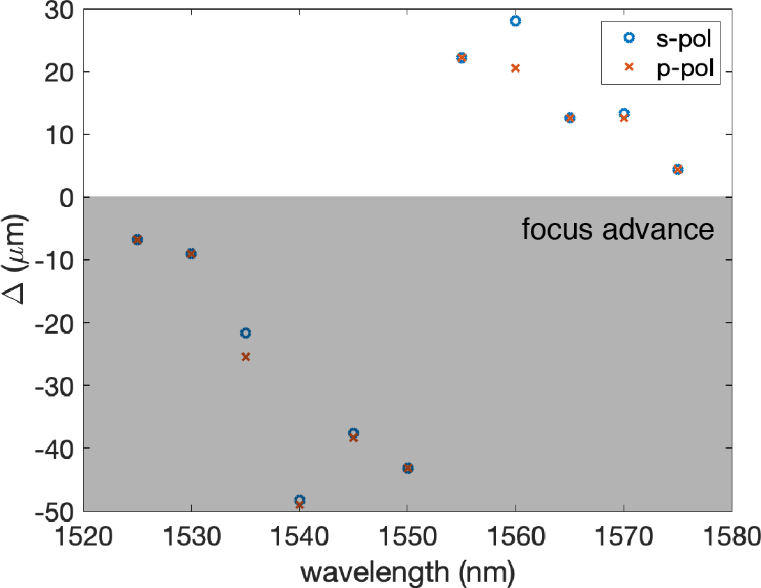
Figure S4 demonstrates the performance of the metamaterial spaceplate for both p-polarized and s-polarized focusing Gaussian beams for operating wavelengths ranging from 1530 nm to 1560 nm.


S4 Homogeneous spaceplate solutions
S4.1 General solution for an angle-dependent refractive index
The goal of a spaceplate is to transform an incoming light-field in an identical manner (for the purposes of imaging) to propagation through a slab of an isotropic homogeneous medium. To do so, the spaceplate must multiply the complex amplitude of each plane-wave in an incoming field by the function, . In particular, a spaceplate of thickness must impart a phase that is equal to the phase due to the propagation through distance of the medium. Both and are along what we set to be the -axis.
In more detail, in a medium of index a plane-wave has phase difference, between two positions separated by vector , where is the wavevector. Here, is the wavenumber in the medium and is the vacuum wavenumber. Inside the spaceplate, the wavevector is . If we consider spaceplates made up of plates or layers whose interfaces are planes, then and due to momentum conservation. Consequently, such a spaceplate will automatically reproduce the contribution to the phase due to displacement in by and , i.e., . The remaining component to be reproduced is the phase due to the displacement along in the medium, . In a homogeneous spaceplate this phase is . With this definition, the goal reduces to making the Fourier transfer function for propagation, , equal for the spaceplate and the medium up to a global offset phase :
| (S1) | ||||
| (S2) |
where is an integer.
If the plane-wave is traveling in the medium at an angle to the -axis, we can express the -component of the wavevector as
| (S3) |
In order to match this variation, the spaceplate must produce an angle-dependent phase. To produce this dependence, one possible scenario is a spaceplate made of a non-isotropic material. That is, we consider a spaceplate material with a refractive index that varies with the wavevector angle inside the spaceplate , such that the wavenumber would be . In this case, the -component of the wavevector is
| (S4) |
where we defined the refractive index ratio, . Since transverse momentum is conserved throughout, we define it as a single parameter . In particular, by the Pythagorean theorem, and, also,
| (S5) |
The goal of these manipulations was to ensure that the only angle that appears in the expressions for both wavevectors is . Note that these relations inherently account for refraction at the interfaces.
We insert the two wavevector equations, Eq. (S4) and Eq. (S5), into the phase condition in Eq. (S1) to obtain,
| (S6) |
We can rearrange this equation to isolate the phase offsets in a single parameter,
| (S7) |
We then solve for and recall the definition of to yield Eq. (2) in the main text, the general equation that describes the index of refraction for a homogeneous spaceplate,
| (S8) |
The physical meaning of can be understood by re-expressing it as
| (S9) |
where we have made the potential dependence of the integer on angle explicit. is the ratio of the total phase offset to the phase accumulated by a wave at angle , traveling distance .

S4.2 Discussion of specific solutions
An infinite family of solutions are parametrized by Eq. (S8). First, there are two branches to the solution corresponding to the positive and negative roots and, second, is arbitrary. In the following subsections, we describe some of these solutions.
S4.2.1 Uniaxial spaceplate
We start with the positive-root solution. We first consider the solution. The refractive index ratio described by this solution is
| (S10) | |||||
Taking the positive root and using , Eq. (S10) can be re-expressed in the standard form for the extraordinary index of a birefringent uniaxial crystal:
| (S11) | ||||
The last line is valid if the crystal has its extraordinary axis along , is negative uniaxial (), , and . In this case, it will impart the ideal angle-dependent phase to mimic of propagation in a medium with .
Since this solution has no global phase offset (), not only will it act as a spaceplate for imaging, it will also replace in an interferometer. This will generally not be true; Consider, for example, an interferometer situated in a vacuum background (). A glass plate of index and thickness can replace the ‘optical path length’ of interferometer arm length. Contrast this with the action of the same glass plate on the focus location of a beam propagating in vacuum. Counter to the situation in the the interferometer, refraction at the plate boundaries makes the focus shift further along the propagation direction, as if it had passed through distance in vacuum [2]. This is the opposite effect to what we seek, showing that the established concept of optical path length is not typically appropriate for a spaceplate. However, since the global phase offset is zero in this case, this uniaxial spaceplate will mimic propagation for the purpose of imaging and interferometry.
S4.2.2 Low-index spaceplate
In the family defined by , is globally smaller than the refractive index of the background medium, i.e., . The special case where exhibits the lowest curvature at in this family. In other words, it is the flattest solution for small angles and, thus, has the lowest dependence on angle. Consequently, an approximation to this solution is a medium with no angular dependence at all, an isotropic medium with a refractive index . For this low-index spaceplate, .
S4.2.3 Other solutions
Many other solutions are possible. For each value of , there is a positive root solution , i.e., taking the sign in Eq. (S8). (Note, can be positive or negative.) Paired with this positive root solution there is a mirror negative root solution , with It is a mirrored about the line, in that the indices have the same magnitude but opposite sign, . A family of negative root solutions will have a refractive index that is positive for all angles, . We plot some of these solutions in Fig. S6c. Critically, it is unknown which index profiles are physically allowable by Maxwell’s equations.
S4.2.4 General properties of the solutions
We now consider some limiting cases for the angle-dependent spaceplate refractive index. We first consider a limit in which both and become large. That is, we take and and take the large limit:
| (S12) |
Consequently, in this limit, all the solutions have the same simple angular dependence up to an overall scaling factor.
Moreover, all the solutions, regardless of and , will fall between these two curves:
| (S13) |
indicated by the black dashed curves in Fig. S6. The compression factor and parameter can be expressed in terms of the value of at two angles. First, at normal incidence,
| (S14) |
Second, while not all solutions give a real-valued refractive index ratio out to , for those that do,
| (S15) |
Consequently, in terms of these two boundaries values of , the compression factor is given by,
| (S16) |
S5 Low-index spaceplate measurements
Section S4.2.2 introduced the solution to Eq. 2 for which . This solution describes a spaceplate index that is lower than that of the background medium for all angles, . It is also the flattest of any solution near and, thus, corresponds to an approximately isotropic medium , particularly for small incident angles. For this low-index spaceplate, .

If the background medium is vacuum, then must be less than one, a seemingly unusual property. Nonetheless, there exist both natural and metamaterials (e.g., epsilon-near-zero (ENZ) materials) from which such a spaceplate can be made[3, 4]. Current low-index () materials are prohibitively lossy [3, 4], so instead of vacuum, we select a background medium with a higher refractive index, linseed oil (which has ), and use air as the low-index medium. The low-index plate is a -mm-long cylinder containing air and faced with glass coverslips. With air as the low index medium (), the resulting compression factor is . We perform the same beam focus advance measurement as for the calcite spaceplate in the main text (as described under Beam Measurements in Sec. S1). The measured shift mm agrees well with the predicted shift of mm.
We next experimentally investigate the transverse displacement of a beam incident on the low-index spaceplate by rotating it with respect to the incoming beam. We see that for larger angles, the displacement induced by the low-index plate deviates from that of an ideal spaceplate (see Sec. S10: S10 Transverse and lateral beam shifts due to a spaceplate). In an imaging system, this discrepancy would act to introduce optical aberrations. This deviation is due to the failure of the small-angle approximation, most dramatically near the onset of total internal reflection at .
Aside from this aberration, total internal reflection imposes a severe limitation on the low-index spaceplate; as its refractive index decreases, its acceptance angle decreases as . Consequently, for the low-index spaceplate, the greater the compression factor is, the smaller the numerical aperture (NA, i.e., ) will be.
S6 Polarization measurements
In this section, we present measurements on polarized beams with the uniaxial spaceplates. Using the polarization control detailed in Section S1, we repeat the beam measurements with an ordinarily polarized beam. While for extraordinarily polarized light the uniaxial crystal acts as a spaceplate, for ordinarily polarized light it acts a homogeneous isotropic medium with refractive index . Consequently, it acts in the opposite manner to a spaceplate; this must be compensated with more propagation distance in a given setup. We measured the uniaxial crystal’s effect on the focal shift of an ordinarily polarized beam and, also, on the beam’s lateral shift when the spaceplate is tilted. The experimental results are shown in Fig. S8. The focal shift observed for the ordinarily polarized beam was mm away from the crystal which agrees well with the theoretical shift mm for .

S6.1 Evidence for a fully two-dimensional spaceplate effect
All three spaceplate types that we have introduced function in both transverse directions, and . That is, the spaceplate advances the propagation of the full two-dimensional spatial distribution of the light-field. To demonstrate this, in this section, we present the same measurement as done in Fig. 3a but now projecting the beam along . Consequently, the plot-vertical gives the intensity distribution along .

S7 Movies
Below are the captions for the movies.
- •
Propagation of a beam in both oil and the air plate (Movie 1) and in both oil and calcite (Movie 2) as a function of beam propagation distance in the oil . The green laser beam looks red due to post-processing. These videos were integrated to produce Fig. 3.
- •
Propagation of a white-light-illuminated image in both glycerol and calcite (Movie 3) as a function of beam propagation distance in the glycerol .
S8 Implications of causality
Causality does not appear to limit the operation of a possible spaceplates with regards to the maximum achievable compression factors . When extrapolating from the demonstrations above, it is evident that a spaceplate can be designed to exhibit an arbitrarily large for a single operating frequency by employing a medium with a sufficiently low refractive index. Instead, this system reveals an explicit trade-off between and the numerical aperture of the spaceplate ()). However, whether this trade-off is inherent to the spaceplate concept or is a consequence of the low-index spaceplate implementation remains an open question. A broadband spaceplate based on an index less than unity would exhibit a violation of microscopic causality, an energy velocity at a point inside the medium that is higher than . Thus, the bandwidth of a low-index spaceplate will also be constrained.
In contrast, a uniaxial spaceplate designed to work in vacuum (, ) will not violate microscopic causality; its operation depends on the ratio of its two refractive indices, and these two quantities are not causally related. To this point, the group index in a non-dispersive uniaxial material is always bounded by its birefringent indices, and , and, thus, the group velocity will always be less than . Indeed, our experimental demonstration supports the prospect of full broadband operation of a spaceplate. Microscopic causality also does not exclude the possibility of spaceplate operation in free space that is based on anisotropic materials.
This conclusion may seem to conflict with intuition derived from experience with other transformation optics-based devices [5], such as an invisibility cloak. A functioning cloak necessitates light travelling within a medium to keep pace with light propagating in the surrounding background. This restriction on macroscopic causality may be relaxed by immersing the device within a high-index medium since then light propagating in the surrounding medium will be slowed. By contrast, a spaceplate encompasses the entire imaging beam, and it has no physical boundary in the direction transverse to the direction of propagation to impose such a strict condition. Therefore, there is no penalty for a beam propagating through a spaceplate to be delayed with respect to another beam propagating in free space alongside it. Consequently, the overall time delay for the imaging light to pass through the spaceplate is unconstrained, becoming a free parameter in spaceplate design. For this reason, we do not foresee any intrinsic issues with limited operation bandwidth in the spaceplate platform, despite evidence to the contrary in other systems.
We suspect that rigorous bandwidth limits could be derived for specific implementations of spaceplates using methods that have already been applied to metasurfaces (e.g., those described in Ref. [6]). These investigations are of interest for future research.
If causality was ultimately revealed to pose a restriction on broadband operation, a spaceplate operating at a single frequency would still be beneficial towards many applications. For instance, there is a great deal of interest in wavefront shaping applications that make use of the transverse degree of freedom of light, such as spatial multiplexing in telecommunications [7], or high-dimensional quantum cryptography [8]. Applications of these type notably operate at a single frequency and could usually benefit from being compressed by a spaceplate. Additionally, as is argued in the main text, many imaging applications only use three colours centered around red, green, and blue frequencies to enable full-colour imaging. A spaceplate that can perform simultaneous compressions for three discrete frequencies could enable full-color imaging without the need of being broadband. The question of broadband operation or causality can, fortunately, be circumvented for these applications.
S9 Fabricated spaceplates
The low-index spaceplate was fabricated by attaching microscope cover slips to both ends of a lens tube using epoxy (Fig. S10a). The uniaxial spaceplate was fabricated by a commercial vendor, which informed us that, in calcite, surfaces normal to the extraordinary axis are difficult to polish well (Fig. S10b). Consequently, some roughness can be observed on the entrance and exit surfaces, resulting in scattering, particularly in the beam measurements.

S10 Transverse and lateral beam shifts due to a spaceplate

As depicted in Fig. 1a in the paper, one expects a spaceplate to shift a beam of light when incident at an angle In this section, we derive the transverse shift and lateral shift . We first derive the shift due to propagating through a slab of medium of thickness , which defines the effect of an ideal spaceplate. We then derive these shifts for the low-index spaceplate and uniaxial spaceplate.
S10.1 Beam shifts due to an ideal spaceplate
Consider a beam traveling in the plane at an angle to the -axis. The beam traverses a region (i.e., a slab) of a medium at length , entering at point and exiting at point (). Upon exiting the region the beam is parallel to the beam that entered the region. That is, its angle is unchanged.
By simple geometry the beam shifts in the -direction by an amount,
| (S17) |
which we name the ‘transverse’ shift. The negative sign is due to a convention that will be explained in the next paragraph. For an ideal spaceplate, the same beam will exit translated along the plate’s interface by an equal amount of transverse shift as created by the slab of medium described above. Another way of looking at the transverse shift is as a displacement from a line that both goes through point and is normal to the plate interfaces. In contrast to the scenario with the medium, this shift now occurs at a distance , the plate thickness.
To test this effect, rather than tilt the incoming beam by , it is experimentally simpler to tilt the studied spaceplate by the same angle. In this case, the quantity that can be measured most directly is the ‘lateral’ shift of the beam. This is the shift of the beam along an axis normal to the beam’s propagation direction. The sign convention mentioned in the last paragraph sets to be positive if the lateral shift is below the path of the incident beam, as depicted in Fig. S11. In particular, would be positive for a beam passing through a tilted regular glass plate in a vacuum background medium.
To relate to , one must account for the tilt of the normal of the plate interface. This alone would result in apparent transverse shift of , which must be added to the actual transverse shift With this established, geometry gives the lateral shift as,
| (S18) |
where we have used .
S10.2 Beam shifts due to a low-index spaceplate
We now consider the lateral shift created by a plate made of an isotropic and homogeneous medium of thickness . If the medium’s refractive index , then the plate is a low-index spaceplate. To start, however, we leave unrestricted. At the entrance interface, incoming light refracts to angle inside the plate according to Snell’s law. In the following, we use Snell’s law to derive analogous relations for and :
| (S19) |
As in Eq. (S17) from the last section, simple geometry shows that the transverse shift of the beam is,
| (S20) |
Likewise, the lateral shift is,
| (S21) |
Substituting Eq. (S19) into Eq. (S21) yields an expression for the lateral shift that is dependent only on ,
| (S22) |
This shows that the lateral shift created by a low-index spaceplate is not equal to the ideal lateral shift given in Eq. (S18). However, using the small angle approximation () we find that
| (S23) |
where we have identified the low-index compression factor, . For large angles, the low-index spaceplate will produce an incorrect shift, effectively introducing aberrations. Moreover, all angles above the critical angle, are perfectly reflected. However, for small angles a low-index plate acts as an ideal spaceplate, i.e., .
While we have derived the lateral shift in the context of a low-index spaceplate, it is actually valid for any value of , including a negative refractive index. Moreover, we use it to describe the action of the uniaxial spaceplate on ordinarily polarized light, which effectively experiences a homogeneous isotropic medium with index . Lastly, the shift also shows that a simple glass plate in air will introduce imaging aberrations for large angles.
S10.3 Beam shifts due to a uniaxial spaceplate
We will now derive the lateral shift created by a uniaxial spaceplate. The uniaxial crystal is characterized by two indices, the extraordinary and ordinary refractive indices, and , respectively. To derive the shift, one must account for the anomalous refraction and consequent beam walk-off that generally occurs with a birefringent medium. In particular, for extraordinarily polarized light in a uniaxial crystal (U), the Poynting vector , which describes the energy flow, can point in a direction different from the wavevector . In contrast, an ordinarily polarized beam will refract normally (i.e., the Poynting and wavevectors are parallel), and, hence, will shift according to Eq. (S23) but with replaced with In the following, we use the results from Ref. [[9]], which carefully analyzed the Poynting vector angle at the interface between a homogeneous medium and a uniaxial crystal with its extraordinary axis (i.e., optic axis) at an arbitrary angle. Since the Poynting vector is the direction an extraordinary beam travels along in the crystal, one can use it to follow a geometric derivation similar to that used in Eq. (S18).
As discussed earlier in the SI, the transverse component of the wavevector is conserved across the interface,
| (S24) |
We apply the results from Ref. [[9]] to the case where the extraordinary axis is normal to the plate interface. In this case, the -component of the wavevector in the crystal can be expressed as:
| (S25) |
If one considers the case where , then , which directly shows why a uniaxial crystal acts as a spaceplate: it produces an angle-dependent phase that is magnified by a factor relative to propagation through a medium with For now, however, we leave general.
Whereas, after refraction at the interface, the wavevector angle in the crystal will be given by , Ref. [[9]] showed that the Poynting vector of an extraordinarily polarized plane-wave will be along a potentially different angle,
where we have used the expressions for the two wavevector components, Eqs. (S24) and (S25).
From here on, we restrict ourselves to the case in which . In this case, the Poynting vector angle reduces to
| (S26) |
where we have identified the compression factor as , as expected from our phase analysis earlier. Using Eq. (S26), the transverse shift for an extraordinarily polarized beam will be
| (S27) |
which can be used to find the associated lateral shift:
| (S28) | ||||
This shows that for all angles, the lateral shift of an extraordinarily polarized beam will be identical to the lateral shift of an ideal spaceplate . In this sense, a uniaxial crystal acts as a perfect spaceplate for the purposes of imaging, replacing medium , while introducing no aberrations.
References
- [1] Kingslake, R. Lens design fundamentals (Academic Press, 2010), second edn.
- [2] Hobbs, P. C. D. Building electro-optical systems: Making it all work (John Wiley & Sons, Inc., Hoboken, NJ, USA, 2009), second edn.
- [3] Engheta, N. Pursuing near-zero response. Science 340, 286–287 (2013).
- [4] Vulis, D. I., Reshef, O., Camayd-Muñoz, P. & Mazur, E. Manipulating the flow of light using Dirac-cone zero-index metamaterials. Reports on Progress in Physics 82, 012001 (2019).
- [5] Monticone, F. & Alu, A. Do Cloaked Objects Really Scatter Less? Physical Review X 3, 041005 (2013).
- [6] Presutti, F. & Monticone, F. Focusing on bandwidth: achromatic metalens limits. Optica 7, 624 (2020).
- [7] Bozinovic, N. et al. Terabit-scale Orbital Angular Momentum Mode Division Multiplexing in Fibers. Science 340, 1545–1548 (2013).
- [8] Sit, A. et al. High-dimensional intracity quantum cryptography with structured photons. Optica 4, 1006 (2017).
- [9] Entezar, S. R. & Habil, M. K. Refraction and reflection from the interface of anisotropic materials. Physica Scripta 94, 085502 (2019).