First-principles Study on Piezoelectricity and Spontaneous Polarization in Bi(Fe,Co)O3
Abstract
Solid solution BiFe1-xCoxO3 shows anti-ferromagnetic order and pyroelectric order, simultaneously. It has been known that BiFe1-xCoxO3 exhibits a structural phase transition between monoclinic and tetragonal phases as increases. This kinds of transition is often called morphotoropic phase boundary, which is well known to take place in a representative piezoelectric oxide, PbZr1-xTixO3. In order to theoretically understand the piezoelectric property in BiFe1-xCoxO3, we performed ab-initio electronic-structure calculations and studied the structural stability, the magnetic property, and the electronic polarization by means of super-cell approach. It turns out that the large electric polarization and the particular pyramidal coordination suppress the response of the electric polarization under strain. A way to enhance the piezoelectric effect in BiFe1-xCoxO3is proposed.
1 Introduction
Multiferroic materials have attracted an increasing amount of attention over several decades due to the physical interest of the cross-coupling phenomena as well as future industrial applications. Multiferroics indicates more than one ferroic orders at the same time, e.g., the combination of ferroelectric, (anti-)ferromagnetic, and ferroelastic orders.[1] A cross-coupling between ferroelectric and magnetic orders may give rise to magnetoelectric (ME) effect, which hopefully enables the electric control of the magnetism and the magnetic control of the ferroelectricity. All the ferroelectric materials show piezoelectric effect to some extent, which is a response of electric polarization to applied mechanical stress, or a response of mechanical strain by electric field. Multiferroics (ferroelectric + magnetic) materials can also include the piezoelectric effect which may be accompanied by the magnetic response to applied stress (magneto-piezoelectric effect) providing potential applications in spintronics.[2]
Among the multiferroic materials, BiFeO3 has been considered as the ‘holy grail’ since the antiferromagnetic order and the large spontaneous polarization occurs at room temperature.[3, 4] BiFeO3 crystallizes in a highly distorted perovskite rhombohedral structure () showing the ferroelectric polarization approximately 100 C/cm2 along the [111] direction in pseudo-cubic perovskite notation,[5] accompanied by a G-type antiferromagnetic order with Néel temperature () of 640 K.
In stark contrast, BiCoO3 crystallizes in a polar tetragonal crystal structure (), quite similar to PbVO3 and shows a C-type antiferromagnetic configuration with of 470 K.[6] The electric spontaneous polarization has been evaluated by a density-functional-theory (DFT) calculation as 179 C/cm2.[7] This giant electric polarization is attributed to the strong hybridization among Bi-, O-, and Co- orbital states, which in turn invokes the high crystal tetragonality (/=1.27, compared to /=1.06 in a prototypical ferroelectric PbTiO3). In the CoO5 pyramidal coordination (see Fig. 1(b)), the minority-spin electron selectively occupies the orbital in Co3+ orbital states.[7] BiCoO3 represents spin-crossover phenomena with an accompanying structural change at high pressure.[8]
Recently, a series of solid solution BiFe1-xCoxO3 (BFCO) has been synthesized in order to tune the electric polarization.[9] Figures 1(a) and (b) are schematic phase diagrams of PbZr1-xTixO3 (PZT) and BFCO, respectively, as a function of solubility . PZT exhibits a high piezoelectric response and is widely used in industry as acoustic sensors and transducers.[10] Around = 0.5 where PZT shows a maximum piezoelectric effect, a morphotropic phase boundary exists. In Fig. 1(a), the phase diagram of PZT is separated to four parts below the Curie temperature. In the Zr-rich phase (), PZT is rhombohedral, and on the other hand the crystal structure is tetragonal in the Ti-rich side (). Between these phases, Noheda [\citenNoheda_Phys.Rev.B2000] found a monoclinic structure () in a vicinity of the morphotropic phase boundary. In this context, Azuma and co-workers expected enhancement in piezoelectricity in the vicinity of the morphotropic phase boundary for BFCO because a monoclinic structure was found in the solid solution BFCO near at room temperature,[12] indicating a promising candidate of lead-free piezoelectric materials. They analyzed the crystal structure by using X-ray diffraction (XRD) patterns in the phase diagram and searched for a polarization rotation with varying temperatures and ratios of solid solution. The spontaneous polarization could not be measured because of large leakage current, but was estimated as 117 by a point charge model.[12] The effective piezoelectric constants has been measured to be 60 pm/V in thin film at .[13] They intensively studied the electric polarization and magnetic order in the rhombohedral structure of BFCO.[14] The enhancement of piezoelectirity is attributed to the presence of a monoclinic phase because the polarization rotates between [001] and [111] in pseudo cubic notation.[15, 16, 17] However, this scenario is not sufficient for BFCO with respect to the polarization rotation. Microscopic investigations may lead to deep insights for the piezoelectricity. In this paper, we calculate the electric polarization and the piezoelectric constants in monoclinic BFCO by using a first-principles DFT approach and investigate the microscopic behavior of ions to mechanical strain.

2 Theoretical Methods
We performed DFT calculations using Vienna ab initio Simulation Package (VASP) within the framework of the generalized gradient approximation adopting the Perdew-Burke-Enzerhof functional (GGA-PBE), while the electron correlation was taken into account by using GGA+ potential (with = 3 eV for transition metal ions[18], to optimize the crystal structure and evaluate the electric polarization and the Born effective charge. Spin-orbit coupling was not taken into account.
The experimental SXRD study has shown that the crystal structure of BiFe2/3Co1/3O3 is monoclinic structure.[12] While Fe and Co atoms are chemically disordered at the perovskite site, in the present calculations, these atoms are ordered with several structural ordered patterns. The structural stability was examined as varying solubility: = 0, 1/4, 1/3, 1/2, 3/4, 1 in the monoclinic and tetragonal structures, whereas in the case of rhombohedral structure the stability is examined for = 0, 1/3, 2/3, 1.
The spontaneous polarization is calculated by using the Berry-phase method.[19, 20] The calculation of the polarization is not straightforward since the centrosymmetric (paraelectric) structure of BiCoO3 leads to a metallic state. This is due to the degeneracy of Co 3- states that is lifted when the polar distortion invokes Jahn-Teller splitting. A computational technique to make an adiabatic path between ferroelecric and antiferroelectric structures avoiding the metallic state is given in appendix A.
Piezoelectric tensor is calculated in a finite strain response scheme.[21] The modulated polarization of ferroelectric system under applied strain is defined as where is original spontaneous polarization and subscripts and denote direction of polarization and Voigt notation, respectively. The piezoelectric coefficients are expressed as
| (1) |
where is the volume of a unit cell, is the lattice parameter, is an ionic index, is the internal coordinates, is the Born effective charge and is the strain tensor element. In Eq. (1), the first term is the clamped-ion term and the second term is the internal strain term. The former is a lattice contribution to the piezoelectricity and the latter comes from relaxation of the ionic coordinates, which is further decomposed into ionic contributions. For example, is defined as a change of polarization along the axis by the strain along the axis. The clamped-ion term is needed to be corrected as , because of an improper contribution from lattice rotation.[22, 23] The Born effective charge defined as
| (2) |
satisfies the sum rule (as well as the nominal charge). The second term in Eq. (1) is obtained from a product of the Born effective charges and ionic displacement by strain.
3 Results and Discussions
3.1 Structural Analysis
The tolerance factor is a good indicator for analyzing prefered distortion in the perovskite structure and calculated from ionic radii as
| (3) |
where and are the ionic radius at the -site and -site cations, respectively, in perovskite oxides. Table 1 shows the tolerance factor in the representative perovskite materials and their cation ionic radii. The ionic radius of O-2 () is assumed to be 1.40 Å.[24] SrTiO3 tends to have a cubic perovskite structure according to . When the tolerance factor is more than unity, the -site cation has a spacial allowance, that leads to a tetragonal structure with ferroelectlicity. In contrast, when the tolerance factor is less than unity, the -site cation has an allowance with the O6 octahedra rotating and tilting, leading to an antiferroelectric order. Note that the ionic radius of Bi3+ of 12 coordination was estimated, assuming that ionic radii are proportional to the coordination number in the same valence. BiFeO3 and BiCoO3 have rhombohedral and tetragonal structures, respectively, in the ground state, although their tolerance factors are near unity, indicating that Bi is a key factor in the ferroelectric distortion.
| (Å) | (Å) | ||
|---|---|---|---|
| BaTiO3 | 1.61 | 0.61 | 1.06 |
| PbTiO3 | 1.49 | 0.61 | 1.02 |
| BiCoO3 | 1.45 | 0.61 | 1.00 |
| SrTiO3 | 1.44 | 0.61 | 1.00 |
| BiFeO3 | 1.45 | 0.65 | 0.98 |
| LaCoO3 | 1.36 | 0.61 | 0.97 |
| PbZrO3 | 1.49 | 0.72 | 0.96 |
The structural stability as varying (Fe, Co) solid solution ratio, , is examined by comparing total energies with tetragonal (space group: ), monoclinic (), and rhombohedral () structures under the G-type antiferromagnetic configuration. Note that magnetic ground states of BiFeO3 and BiCoO3 in reality are G- and C-type antiferromagnetic, respectively, while the energy difference between these antiferromagnetic orders is prety small compared to the energy difference between different structures. Both the atomic coordinates and lattice parameters are optimized until the atomic force less than 0.005 eV/Å. As shown in Fig. 2, the overall trend of the stable structure, i.e., rhombohedral structure at (at BiFeO3), monoclinic structure at , and tetragonal structure at (at BiCoO3), is consistent with experimental results (see Fig. 1(b)). Diéguiez and Íñiguez reported that the structure change around from the formation energy with a DFT calculation.[25] At , the monoclinic structure is optimized to be almost identical structure to the tetragonal structure. In PZT the monoclinic structure leads to the enhancement of the piezoelectric coefficients, and therefore the monoclinic structure in BiFe1-xCoxO3 may also result in the strong piezoelectric effect.
3.2 Magnetic Coupling
BiFeO3 shows the G-type antiferromagnetic order: the Fe3+ spin moments are ferromagnetically coupled in the pseudo cubic (111) plane and antiferromagnetically coupled between the adjacent planes. The easy axis of the magnetic moments lies in a plane perpendicular to the [111] direction. The magnetic symmetry in the AFM phase permits the spins canting in the plane with the cycloidal modulation with a period of 62 nm measured.[26] In the case of BiCoO3, the Co3+ spin moments are ordered in a C-type antiferromagnetic configuration. The magnetic easy axis is in the [001] direction.[27] To our best knowledge, the spin configuration in monoclinic BiFe1-xCoxO3 is not known. In order to investigate the magnetic interaction of Fe3+ and Co3+ ions in BiFe0.75Co0.25O3 solid solution, a four-formula-unit monoclinic supercell is adopted. The cell is the minimum setting in a range of solubility in the monoclinic phase (). The total energy obtained by DFT calculations was mapped onto a classical Heisenberg Hamiltonian, , where denotes pairs of spins at and sites and is classical spin. With this cell, the Hamiltonian is described as

| (4) |
where the Heisenberg exchange parameters are displayed in Fig. 3 and coefficients in each term express the coordination number. For example, is an out-of-plane exchange parameter between Fe1 and Co, is an out-of-plane exchange parameter between Fe2 and Co, and is an exchange parameter of diagonal pair of Fe3 and Co in the unit cell (see Fig. 3).
To evaluate the exchange parameters, , the energy difference is compared as considering different spin configurations. The Heisenberg parameters are calculated by solving a simultaneous equations . The spin configurations and total energy differences from the ferromagnetic order are listed in Table 2. From the energy differences, one can get the Heisenberg exchange parameters to solve Eq. (3.2),
| Co | Fe1 | Fe2 | Fe3 | (eV) |
|---|---|---|---|---|
| 0 | ||||
| -0.1339 | ||||
| -0.8632 | ||||
| -0.9021 | ||||
| -0.4287 | ||||
| -0.4445 | ||||
| -0.5111 | ||||
| -0.5129 |
where this matrix is a coefficient matrix. In order to solve the 76 matrix, the least-square solution method is employed as minimizing a sum of square error for each matrix column: . If all column vectors of the coefficient matrix are linearly independent, satisfy a following equation,
| (19) |
The calculated Heisenberg exchange parameters in the model super cell of BiFe0.75Co0.25O3 are listed in Table 3. The sum of square error is eV2, which is sufficiently small.
| [meV] | -2.52 | -27.84 | -1.49 | -3.40 | -23.13 | -1.21 |
|---|
In general, the critical temperature is estimated within the mean-field approximation (MFA) for a multisublattice spin system by diagonalizing coupled equations, [28]
| (20) |
where is the coordination number of and is the Boltzmann constant. Equation (20) can be further written down in the form of the eigenvalue matrix problem
| (21) |
where , and the eigenvectors express the spin configurations. The Néel temperature is 871 K and spin configuration is C-type antiferromagnetic like ferrimagnetic in BiFe0.75Co0.25O3. In the case of BiCoO3, the Néel temperature was 905 K with C-type antiferromagnetic. In the case of , was reported as 400 K in the tetragonal structure with Monte Carlo simulation.[25]
3.3 Electric Polarization and Piezoelectricity
3.3.1 Piezoelectricity in BiFe2/3Co1/3O3
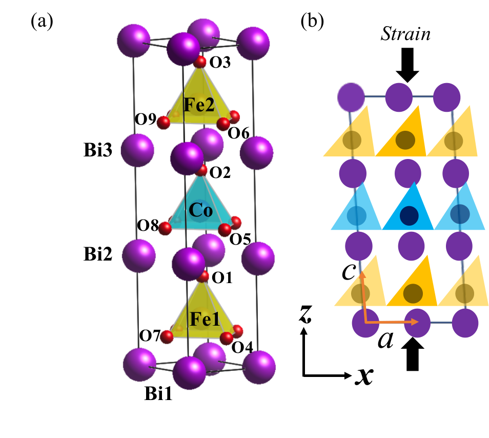
In order to calculate the piezoelectric properties in the solid solution BiFe1-xCoxO3 with , a model cell is built, including 30 atoms (see Fig 4(a)). The cell is monoclinic structure with a (10) mirror plane. The initial atomic structure is taken from the experimental structure[12] reported at and is fully relaxed. The lattice parameters are shown in Table 4. Lattice vectors in the monoclinic cell, and , are parallel to the pseudo cubic [110] and [] axes, respectively, while is almost parallel to the [001] direction with a small tilt angle. The polarization components and along the and axes of the fully relaxed monoclinic structure are calculated as 155 and 35 , respectively. Here, is forbidden by the (10) mirror symmetry. The size of the calculated polarization is consistent with those of a film at obtained by experiment.[29] The tilting of the polarization direction with respect to the axis has an important role to enhance the piezoelectricity. When the mechanical strain is applied along the axis, the total polarization direction may rotate within the mirror plane as shown in Fig. 4(b). This polarization rotation caused by the simultaneous deformation of oxygen pyramids, significantly decreases and increases .
| (Å) | (Å) | (Å) | (deg.) | |||
|---|---|---|---|---|---|---|
| Exp.a | BiFe0.7Co0.3O3 | 5.306 | 5.300 | 4.708 | 91.36 | 1.256 |
| DFT | BiFe2/3Co1/3O3 | 5.255 | 5.247 | 4.702 | 91.25 | 1.266 |
Piezoelectric -constants are calculated as a combination of a clamped-ion term and an internal-strain term as in Eq. (1). For the first term, the internal coordinates is fixed and the unit cell is distorted by strain. This term is the contribution from the strained lattice. The second term is calculated by using the Born effective charges and the slopes of internal coordination with respect to the strain. These slopes are obtained from relaxation calculations for the internal coordinates under strain. The calculated Born effective charges are listed in Table 5 as obtained by Eq. (2), where each ion is displaced by 0.01 Å ( satisfies the sum rule ()). Difference between the Born effective charges and nominal charges comes from hybridization effect.[30] For example, Co and Fe ions show larger than and due to the strong hybridization with the apical oxygen ions with the polar distortion while Bi ion in contrast shows larger and than due to the hybridization with both the apical and side oxygen ions. At the relaxed structure, piezoelectric tensors are calculated as C/m2, C/m2, C/m2, and C/m2. The resulted values are much smaller than what we expected in analogy to PZT ( C/m2 and C/m2 in PZT[16]). In the following, we will discuss this difference in detail.
| Ion | |||
|---|---|---|---|
| Co | 2.47 | 2.46 | 3.31 |
| Fe1 | 3.05 | 3.04 | 3.99 |
| Fe2 | 3.04 | 3.04 | 4.06 |
| Bi1 | 5.26 | 5.14 | 3.79 |
| Bi2 | 5.30 | 5.25 | 3.61 |
| Bi3 | 5.27 | 5.23 | 3.73 |
| O1 | -2.55 | -2.54 | -3.40 |
| O2 | -2.40 | -2.33 | -3.05 |
| O3 | -2.50 | -2.37 | -3.42 |
| O4 | -2.91 | -2.89 | -2.20 |
| O5 | -2.69 | -2.64 | -1.92 |
| O6 | -2.91 | -2.90 | -2.18 |
| O7 | -2.91 | -2.89 | -2.21 |
| O8 | -2.65 | -2.64 | -1.92 |
| O9 | -2.90 | -2.90 | -2.18 |
| Sum | -0.03 | 0.06 | 0.00 |
In order to investigate how the piezoelectricity develops around the morphotropic phase boundary in BiFe1-xCoxO3, the monoclinic distortion angle () and ratio are varied at the fixed volume. The ratio is varied from 1.250 to 1.290 Å with 0.002 Å interval while is varied from 91.25∘ to 90.00∘ with 0.25∘ interval so that the piezoelectric constants are calculated for total 126 structures. The calculated and are shown in Fig. 5. The values of changes sensitively to (showing large values around =90.5∘) but not to . The trends of and are found to inverse correlation and polarization rotation does not occur when the strain is applied. The maximum magnitude of is C/m2 at and . On the other hand, the peak value of is 1.84 C/m2 at and . It should be emphasized that the enhancement of piezoelectricity occurs within the monoclinic phase, not near the phase boundary of monoclinic and tetragonal structure. In PZT, piezoelectric coefficient, , is 12.6 C/m2 in the vicinity of the morphotropic phase boundary.[16] In contrast, of the present BFCO shows about seven times as small as that of PZT.

In the perovskite piezoelectric oxides, the mechanism of enhancement in the piezoelectric constants is often attributed to the polarization rotation.[17, 15, 16] For example, Wu and Krakauer [\citenWu_Phys.Rev.B2003] have studied the piezoelectricity in PZT with a first-principles calculation and reported that the significant development of polarization along the axis under strain along the axis and the polarization rotation increases the piezoelectric constants. In the case of BFCO, the enhancement of piezoelectricity can be seen in several and points, but rather small. Besides, the enhancements in do not have correlation with change in polarization along the axis. The piezoelectric coefficients are dominantly determined by the internal-stain term in Eq. (1), especially the derivative of the ionic displacement with respect to the strain. Figure 6 shows the ionic displacement by strain at and , where shows the maximum value in our calculations. From Fig. 6, it can be found that the piezoelectricity come from the bismuth and apical oxygen that move along the direction whereas the transition-metal ions and the side oxygen atoms are not much displaced. The ionic behavior comes from the fact that in monoclinic BFCO the apical oxygen atom is not shared by two pyramids so that the apical oxygen ion can move freely but the side oxygen ions and the transition metal ion in the pyramid are not much affected by the external strain. Since the inter-layer interaction of these ionic displacement is weak, the polarization rotates very insensitively under strain. This is crucially different from what happens in PZT, where the transition-metal ion in the octahedron cage shows off-centering displacement along the diagonal direction so that decreases and increases at the same time. Therefore, in BFCO the polarization rotation is not expected to enhance the piezoelectricity.
To improve such poor piezoelectricity in BFCO, lowering the spontaneous polarization might be considered. Phenomenologically, the piezoelectricity can be large with small spontaneous polarization since the piezoelectric coefficients can be represented as a product of dielectric constants and spontaneous polarization, while the dielectric constants decreases more rapidly than the polarization increases.[31] Doping La or Y atom at the -site is a possible strategy. According to Cazola et al.,[32] Bi3/4La1/4CoO3 can be synthesized. When the large spontaneous polarization caused by Bi-O hybridization is suppressed, the pyramidal cage will be deformed towards an octahedral cage. Then the situation becomes similar to that of PZT, so that the piezoelectricity may be enhanced.

3.3.2 Piezoelectric d-constants in BFCO of thin film structures
The BFCO exhibits two kinds of monoclinic and tetragonal structures in thin film grown on LaAlO3 substrate.[13] MC-type monoclinic structures are realized in =0–0.10, which lattice tilts toward [010] pseudo cubic direction defined as the axis with the in-plane electric polarization (). The second monoclinic structure is MA-type monoclinic structures (=0.15–0.40), which are equivalent with the monoclinic structure in bulk. Increasing the solubility (), the crystal structure becomes tetragonal structure like BiCoO3. The piezoelectric d-constants are calculated in MC-type monoclinic BiFeO3 (=0), MA-type monoclinic BiFe0.25Co0.75O3 and BiFe2/3Co1/3O3, and tetragonal BiFe0.5Co0.5O3 shown in Table 6. The piezoelectric d-constants are obtained from a product of piezoelectric e-constants and compliance that is the inverse tensor of the elastic constants (), for example, with the Voigt notation. The calculated value for the tetragonal structure shows good agreement with the experimental value. On the other hand, the for three monoclinic structures are smaller than the experimental results. It should be noted that the linear response of piezoelectricity was taken into account in our calculation while the experimental values have been obtained from maximum value of non-linear - curves applying electric fields.[13] Therefor these values are not well comparable. However, our results reproduce the trend of increasing the value with decreasing the solubility . The enhancement of piezoelectricity occurs in MC-type monoclinic structure.
| 0 | 10.98 | 16.86 | 39.8 |
| 0.25 | 17.38 | 69.17 | 52.1–57.5 |
| 0.33 | 8.54 | 22.22 | - |
| 0.5 | 7.84 | 0 | 10.8 |
The piezoelectric -constants are enhanced at by and strain in Fig. 7. The main contribution of comes from the and . By contrast, the values of are not remarkably changed with the solubility. When the unit cell is strained along the axis, component of the electric polarization is decreased. The ionic radii of the Co3+ is smaller than that of Fe3+ so that the pyramidal structure of Co is considered to be destabilizing at =0.25.The piezoelectric -constants reflect the competition between rhombohedral and tetragonal tendency. At , the sign of is positive because MC-type monoclinic lattice tilts toward [010] pseudo cubic plane where apical and side oxygens are located in the same distorted plane. MA-type monoclinic lattice tilts toward [110] pseudo cubic plane so that the apical oxygen can move more because the apical and side oxygens are not in the same strain direction. The sign of is changed at =0.25, as electric polarization decreases applying strain. mainly comes from and in Fig. 7(b). The BFCO responds greatly to and .
4 Conclusions
We have evaluated the piezoelectric -constants in monoclinic BFCO at as varying ratio and monoclinic distortion angle. The enhancement of piezoelectricity is found in monoclinic structures. The magnitude of is rather small since the mechanism of the enhancement of piezoelectricity is different. The polarization rotation in PZT is a plausible explanation of the enhancement of piezoelectricity because the octahedron of Zr and Ti share the apical oxygen. Therefore, in-plane and out-of-plane electric polarizations cooperatively change. However, in BFCO, bismuth and not shared apical oxygen primarily contribute to the piezoelectricity with displacement of ions by strain. The pyramidal polyhedron make the apical oxygen possible to move independently and to induce the displacement of bismuth. The piezoelectric -constants are calculated in different solubility and the trend of shows that the enhancement of piezoelectricity occur with monoclinic structure. The main factor of the is not , but and . The is also show the enhancement of piezoelectricity at and which is promising material for the lead-free material.
Acknowledgements.
The computations in this study were performed using the facilities of Supercomputer Center at ISSP, University of Tokyo. We would appreciate Dr. Silvia Picozzi and Dr. Paolo Barone for invariable discussion. This work was supported by JSPS Kakenhi, Grants No. 17H02916.Appendix A Polarization Calculation in Pyroelectric Materials
This Appendix is contributed to explain the method of numerical calculation for spontaneous polarization in pyroelectric materials by using DFT calculation. In modern approach, Berry phase method is a good tool for the calculation, but it has uncertainty by quantum polarization. Electric polarization is calculated from paraelectric structure to ferro- (antiferro-) electric one in an adiabatic path. Most materials remain insulating in paraelectric structure but some ferroelectrics, for example BiCoO3, is not insulating in the paraelectric case. Electric polarization should be calculated in an insulating and adiabatic path. The problem is how can we obtain an adiabatic path without a metallic state from paraelectric to ferroelectric phases.
BiCoO3 is an example material, which shows giant spontaneous polarization and high-tetragonality. In the ground state, BiCoO3 is distorted and octahedral CoO6 becomes to pyramidal structure, because of Jahan-Teller effect. Co3+ ion is six electron configuration in orbital, the states are all occupied in the majority-spin bands, while in the minority-spin bands, only the orbital is selectively occupied. In case of paraelectric structure, BiCoO3 shows metallic because of the minority-spin band.
Our approach is achieved by comparing electric polarization of ferroelectric with antiferroelectic. In this approach, electric polarization is calculated within insulating. Figure 9 is an adiabatic path from an antiferroelectric to ferroelectric structures. The value of the electric polarization along the axis is 171 C/cm2.

References
- [1] H. Ohno, Science 281, 951 (1998).
- [2] T. Nakajima, Y. Tokunaga, Y. Taguchi, Y. Tokura, and T.-h. Arima, Phys. Rev. Lett. 115, 197205 (2015).
- [3] M. Fiebig, T. Lottermoser, D. Meier, and M. Trassin, Nat. Rev. Mater. 1, 16046 (2016).
- [4] G. Catalan and J. F. Scott, Adv. Mater. 21, 2463 (2009).
- [5] J. B. Neaton, C. Ederer, U. V. Waghmare, N. A. Spaldin, and K. M. Rabe, Phys. Rev. B 71, 014113 (2005).
- [6] A. A. Belik, S. Iikubo, K. Kodama, N. Igawa, S.-i. Shamoto, S. Niitaka, M. Azuma, Y. Shimakawa, M. Takano, F. Izumi, and E. Takayama-Muromachi, Chem. Mater. 18, 798 (2006).
- [7] Y. Uratani, T. Shishidou, F. Ishii, and T. Oguchi, Jpn. J. Appl. Phys. 44, 7130 (2005).
- [8] K. Oka, M. Azuma, W.-t. Chen, H. Yusa, A. A. Belik, E. Takayama-Muromachi, M. Mizumaki, N. Ishimatsu, N. Hiraoka, M. Tsujimoto, M. G. Tucker, J. P. Attfield, and Y. Shimakawa, J. Am. Chem. Soc. 132, 9438 (2010).
- [9] M. Azuma, S. Niitaka, N. Hayashi, K. Oka, M. Takano, H. Funakubo, and Y. Shimakawa, Jpn. J. Appl. Phys. 47, 7579 (2008).
- [10] K. Uchino, Piezoelectric Actuators and Ultrasonic Motors, Electronic Materials: Science & Technology (Springer US, 1997).
- [11] B. Noheda, J. A. Gonzalo, L. E. Cross, R. Guo, S.-E. Park, D. E. Cox, and G. Shirane, Phys. Rev. B 61, 8687 (2000).
- [12] K. Oka, T. Koyama, T. Ozaaki, S. Mori, Y. Shimakawa, and M. Azuma, Angew. Chem. Int. Ed. 124, 8101 (2012).
- [13] K. Shimizu, H. Hojo, Y. Ikuhara, and M. Azuma, Adv. Mater. 28, 8639 (2016).
- [14] H. Hojo, K. Oka, K. Shimizu, H. Yamamoto, R. Kawabe, and M. Azuma, Adv. Mater. 30, 1705665 (2018).
- [15] D. Vanderbilt and M. H. Cohen, Phys. Rev. B 63, 094108 (2001).
- [16] Z. Wu and H. Krakauer, Phys. Rev. B 68, 014112 (2003).
- [17] H. Fu and R. E. Cohen, Nature 403, 281 (2000).
- [18] A. Walsh, S.-H. Wei, Y. Yan, M. M. Al-Jassim, J. A. Turner, M. Woodhouse, and B. A. Parkinson, Phys. Rev. B 76, 165119 (2007).
- [19] R. Resta, Ferroelectrics 136, 51 (1992).
- [20] D. Vanderbilt and R. D. King-Smith, Phys. Rev. B 48, 4442 (1993).
- [21] G. Sághi-Szabó, R. E. Cohen, and H. Krakauer, Phys. Rev. Lett. 80, 4321 (1998).
- [22] D. F. Nelson and M. Lax, Phys. Rev. B 13, 1785 (1976).
- [23] D. Vanderbilt, J. Phys. and Chem. of Sol. 61, 147 (2000).
- [24] R. D. Shannon, Acta Cryst. A 32, 751 (1976).
- [25] O. Diéguez and J. Íñiguez, Phys. Rev. Lett. 107, 057601 (2011).
- [26] I. Sosnowska, T. P. Neumaier, and E. Steichele, J. Phys. C: Solid State Phys. 15, 4835 (1982).
- [27] Y. Uratani, T. Shishidou, and T. Oguchi, J. Phys. Soc. Jpn. 78, 084709 (2009).
- [28] E. Şaşıoğlu, L. M. Sandratskii, and P. Bruno, Phys. Rev. B 70, 024427 (2004).
- [29] H. Hojo, R. Kawabe, K. Shimizu, H. Yamamoto, K. Mibu, K. Samanta, T. Saha-Dasgupta, and M. Azuma, Adv. Mater. 29, 1603131 (2017).
- [30] K. Terakura and S. Ishibashi, in Proceedings of Computational Science Workshop 2014 (CSW2014) (J. Phys. Soc. Jpn., Tsukuba, Japan, 2015) p. 011018.
- [31] M. Budimir, D. Damjanovic, and N. Setter, Phys. Rev. B 73, 174106 (2006).
- [32] C. Cazorla, O. Diéguez, and J. Íñiguez, Sci. Adv. 3, e1700288 (2017).