DesignBIP: A Design Studio for Modeling and Generating Systems with BIP
Abstract
The Behavior-Interaction-Priority (BIP) framework — rooted in rigorous semantics — allows the construction of systems that are correct-by-design. BIP has been effectively used for the construction and analysis of large systems such as robot controllers and satellite on-board software. Nevertheless, the specification of BIP models is done in a purely textual manner without any code editor support. To facilitate the specification of BIP models, we present DesignBIP, a web-based, collaborative, version-controlled design studio. To promote model scaling and reusability of BIP models, we use a graphical language for modeling parameterized BIP models with rigorous semantics. We present the various services provided by the design studio, including model editors, code editors, consistency checking mechanisms, code generators, and integration with the JavaBIP tool-set.
1 Introduction
Modeling languages are often used for designing complex systems. Using dedicated design studios allows increasing the understandability and usability of modeling languages, as well as decreasing development costs by eliminating errors at design time. Design studio components can be organized in the following three categories: 1) semantic integration, 2) service integration, and 3) tool integration. Semantic integration components comprise the domain of the modeling language, i.e., its metamodel that explicitly specifies the building blocks of the language and their relations. Service integration components include dedicated model editors, code editors, and GUI/Visualization components for modeling and simulating results. Additionally, service integration components include model transformation and code generation services, model repositories, and version control services. Finally, tool integration components consist in integrated tools such as run-times and verification tools.
Figure 1 shows the main steps of the workflow of a design studio. Initially, models are designed using dedicated model editors. Optionally, design patterns stored in model repositories may be used to simplify the modeling process. Next, the checking loop starts (step 1), where the models are checked for conformance. If the required conformance conditions are not satisfied by the model, the checking mechanism must point back to the problematic nodes of the model in the model editor and inform the developer of the inconsistency causes to facilitate model refinement. Finally, when the conformance conditions are satisfied (step 2), the refined models may be analyzed and/or executed (step 3) by using integrated, into the design studio, third party tools. The output of the tools is then collected and sent back to the model editors (step 4) for visualization of analysis or execution results.

We present the DesignBIP studio for modeling and generating systems with the BIP [3] framework. BIP comprises a language with rigorous operational semantics and a dedicated tool-set including code generators, run-time support tools, i.e., BIP engines, and verification tools [6, 8]. Depending on the application domain, BIP offers several compilation chains, targeting different execution platforms and programming languages such as C++ [3] Java [9] Haskell, and Scala [15].
The specification of models in the BIP framework is done by using the BIP language in a textual manner [2] without offering any dedicated code editors. Thus, developing large systems with the BIP toolset can be challenging and error prone. In DesignBIP we have opted for a graphical language to enhance readability and easiness of expression. DesignBIP offers a complete modeling solution, in which we have integrated the tools offered by JavaBIP, the Java-based implementation of BIP [9]. Relying on the observation that systems are usually built from multiple instances of the same component type, we propose a parameterized graphical language for BIP that enhances scalability and reduces the model size.
DesignBIP is a web-based, collaborative, version controlled design studio based on WebGME [22]. DesignBIP allows real-time collaboration between multiple developers. Project changes are committed and versioned, which enables branching, merging and viewing the history of a project. DesignBIP11 1 https://cps-vo.org/group/BIP is easily accessed through a web interface and is open source22 2 https://github.com/anmavrid/DesignBIP. Our contributions are as follows:
- •
We extend architecture diagrams [23], a graphical parameterized language, to accommodate the specification of BIP parameterized models.
- •
We prove a set of necessary and sufficient conditions for checking the encodability of parameterized BIP graphical models into logical formulas.
- •
We study the model transformation from graphical models to logical formulas and develop code generation plugins.
- •
We develop dedicated BIP model editors, code editors, and model repositories.
- •
We integrate the JavaBIP engine and provide visualization of its output.
Paper organization: Section 2 describes the BIP language. Section 3 describes the parameterized graphical language of DesignBIP. Section 4 describes service integration components, i.e., model and code editors, model repositories, and code generators. Section 5 describes the integration with the JavaBIP engine. Section 6 discusses related work. Section 7 discusses concluding remarks and future work.
2 The BIP Language
Component behavior in BIP is described by Labeled Transition Systems (LTS). LTS transitions are of three types: enforceable, spontaneous, and internal33 3 JavaBIP includes all three, whereas BIP1 and BIP2 include the enforceable and internal types.. Enforceable transitions are handled by the BIP-engine and are labeled with ports. Ports form the interface of a component and are used to define interactions with other components. Spontaneous transitions take into account changes in the environment and, thus, they are not handled by the BIP-engine but rather executed after detection of external events. Finally, internal transitions allow a component to update its state based on internal information.
An interaction in BIP is a non-empty set of ports that defines allowed synchronization of actions among components. BIP interactions represent a clean, abstract concept of architecture which is separated from component behavior. Interaction models can be represented in many equivalent ways. Among these are connectors [10] and Boolean formulas [11] on variables representing port participation in interactions. Connectors are most appropriate for graphical design and interaction representation, whereas Boolean formulas are most appropriate for efficient encoding and manipulation by the BIP-engine.
BIP connectors contain ports, which form their interface. Each port of a connector has an attribute trigger (represented by a triangle, Figure 2(a)
3 Semantic Integration Components
We present the BIP parameterized graphical language that was integrated in DesignBIP. The DesignBIP metamodel can be found in the technical report [24].
3.1 Architecture Diagrams for BIP
Architecture diagrams [23] is a parameterized graphical language for the description of the structure of a system by showing the system’s component types and their attributes for coordination.We extend the definition of architecture diagrams with triggers and synchrons to define BIP connectors. A BIP architecture diagram consists of a set of component types and a set of connector motifs. Each component type is characterized by a set of port types and a cardinality parameter , which specifies the number of instances of . Figure
3.1.1 Conformance Conditions
DesignBIP encodes connector motifs in the Require/Accept macronotation (Section 2) in order to give the latter as input to the integrated JavaBIP-engine. Nevertheless, the semantic domains of BIP architecture diagrams and interaction logic (Section 2) do not coincide. An architecture diagram defines a set of configurations, whereas, an interaction logic formula defines exactly one configuration. Consider the architecture diagram shown in Figure
4 Service Integration Components
We present the model and code editors, the code generators, and the model repositories of DesignBIP.
4.1 Model and Code editors

A developer provides the system specification by using the dedicated model and Java code editors of DesignBIP. In particular, the developer must specify 1) component behavior in the form of BIP LTS, 2) component interaction in the form of BIP architecture diagrams and 3) the actions associated with transitions and guards, as well as variable declarations directly in Java. Figures 8 and 9 present the DesignBIP LTS and BIP diagram model editors, as well as the Java code editor. In the code editor, the darker parts represent code that was automatically generated by the input given in the model editors, while the bright code parts represent input given directly in the code editor. In the LTS model editor, enforceable and internal transitions are illustrated with solid arrows, while spontaneous transitions are illustrated with dashed arrows. The code and model editors are tightly synchronized, i.e., changes are instantaneously propagated.

4.2 Behavior generation plugin: LTS to Java code
As explained earlier, a developer graphically specifies the LTS that represents component behavior. DesignBIP generates the Java code that describes the LTS specified by the developer. In particular, DesignBIP generates code in the form of Java annotations that describes the ports, component types, transitions, and guards of each LTS. For instance, Java annotations describing the ports of the Route component type (Figure 9) are shown in the right-hand side of Figure 8.
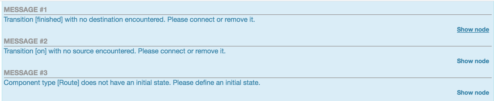
Firstly, before the plugin generates the Java code, it checks the correct instantiation of each specified LTS according to the constraints defined in the DesignBIP metamodel, which can be found in the technical report [24]. For instance, the plugin checks whether each LTS has exactly one initial state. If errors exist, DesignBIP returns to the developer a message explaining the error and pointers (displayed as Show node) to the incorrect nodes of the specified model as shown in Figure 10. In the case of a correct behavioral model, DesignBIP returns a set of Java files, i.e., one Java file for each specified component type. The complete generated Java annotations for the Route component type can be found in the technical report [24].
4.3 Interaction generation plugin: BIP architecture diagrams to XML code
We propose Algorithm 1, with polynomial-time complexity for the encoding of a BIP architecture diagram into Require/Accept macros (Section 2). For each port type, we instantiate two sets of variables: require and accept. For the sake of simplicity, we write instead of .
/* for each port type p in the diagram */
for do
/* for all connector motifs attached to p */
for do
if then
if then
else
if trigger then
/* else if there exists at least one trigger */
else if then
[]. /* else add all ports as many times as their multiplicity */
else
for do
[].add(optionRequire[]); return and ;
The accept set of contains the right hand side of and is constructed as follows. For each connector motif attached to , if its size is: 1) equal to , i.e., singleton connector motif, then we add - in accept44 4 The dash - indicates that must not synchronize with any other port.; 2) greater than and the multiplicity of is greater than , we add in accept all port types of the connector motif including ; 3) greater than and the multiplicity of is equal to , we add all port types of the connector motif except for to accept.
The require set of contains the right hand side of and is constructed as follows. For each connector motif attached to , if its size is: 1) equal to or is typed as trigger then we add - to require55 5 The dash - indicates that does not require any other port for synchronization.; 2) greater than and there exists at least one trigger, we add to require as many options as the number of triggers. In each option we add a trigger; 3) greater than and there are no triggers, we add to require all port types of the connector motif except for as many times as their associated multiplicity and times the port type , to form a single option.
Before generating the XML code, DesignBIP checks the conformance conditions presented in Section ref:conformance. Additionally, DesignBIP checks the correct instantiation of the multiplicity and degree constraints of each connector motif. If errors exist, DesignBIP returns to the developer messages explaining the errors and pointers to the incorrect nodes of the model. In the case of a correct interaction model, DesignBIP returns an XML file with the generated code. Part of the generated XML code for the Switchable Routes example (Figure 9) can be found in the technical report [24].
4.4 Model repositories
To promote reusability in DesignBIP, each project is accompanied by component type and coordination pattern [25] repositories. For instance, let us consider the mutual exclusion coordination pattern shown in Figure 11 that enforces the no two processes can use the shared resource simultaneously coordination property. The shared resource is managed by the unique —due to the cardinality being —Mutex Manager component type. The multiplicities of all port types are and therefore, all connectors are binary. The degree constraints require that each port instance of a component of type Process be attached to a single connector and each port instance of the Mutex Manager be attached to connectors. The behaviors of the two component types enforce that once the resource is acquired by a component of type Process, it can only be released by the same component.
To use a coordination pattern, a developer needs to create an instance of the pattern in the model and evaluate its cardinality parameters. For instance, if the developer wants to enforce mutual exclusion on two instances of Process then must be set equal to .
5 JavaBIP-engine Execution and Visualization
After generating the system specification, the developer may use the integrated JavaBIP-engine to execute it. The JavaBIP-engine is offered through a dedicated plugin in DesignBIP. If the cardinality parameters of the component types have not been evaluated, the plugin asks the developer to provide the number of instances of each component type. It then instantiates the components and passes their reference to the JavaBIP-engine alongside with the generated Java and XML code. The plugin starts the JavaBIP-engine that runs the following three-step protocol in a cyclic manner: 1) upon reaching a state, each component notifies the JavaBIP-engine about possible outgoing transitions, 2) the JavaBIP-engine computes the possible interactions of the system, picks one, and notifies the involved components, 3) the notified components execute the functions associated with the corresponding transitions.
The output of the JavaBIP-engine (which transitions are picked at each execution cycle) is stored as a JSON object. When the plugin stops the execution of the engine (the execution time is defined by the developer), the output is sent back to the model editors of DesignBIP for simulation (see Figure 12). Initially, the developer picks the subset of components whose execution wants to simulate. Starting by highlighting the initial states of these components, the visualizer shows which transitions are executed in each execution cycle by firstly highlighting the fired transitions and finally their destination states.

6 Related Work
Model-driven component-based software engineering and development [7, 17, 30] has become an accepted practice for tackling software complexity in large-scale systems. It provides mechanisms to support design at the right level of abstraction, error detection, tool integration, verification and maintenance. Systems are built by composing and reusing small, tested building blocks called components.
The Generic Modeling Environment (GME) and its successor WebGME are open source Model Integrated Computing (MIC) tools developed for creating domain specific modeling environments and has been effectively applied to a number of domains [29, 31, 27, 4].
Close to our approach is the ROSMOD design studio [20] that also relies on WebGME for collaborative code development and model editing features. The basic building blocks of ROSMOD are specified in its metamodel which is described in UML class diagrams [5]. The code development and compilation process have been integrated in the graphical user interface to keep the framework self-sufficient. ROSMOD integrates code development, code generation, compilation, run-time monitoring, and execution time plot generation. Nevertheless, in ROSMOD component behavior is defined directly with code and thus connection to verification tools is not supported.
A plethora of approaches exists for architecture specification. Patterns [14, 18] are commonly used for specifying architectures in practical applications. The specification of architectures is usually done in a graphical way using general purpose graphical tools. Such specifications are easy to produce but their meaning may not be clear since the graphical conventions lack formal semantics and thus are not amenable to formal analysis. Significant work has been done by the Architecture Description Languages (ADLs) community. Many ADLs have been developed for architecture specification [26, 28] with rigorous semantics that facilitate communication of system properties and allow system analysis. Nevertheless, according to [21], architectural languages used in practice mostly originate from industrial development (e.g., UML) instead of academic research (e.g., ADLs). Scientific questions remain about UML’s formal properties [16]. The use of UML has been demonstrated in [13, 19] for representing architectural concepts with a focus on the component and connector view. However, exploiting these constructors to express architecture views may result in a proliferation of models and stereotypes, which can be difficult to integrate into a well-structured code generation process. On the other hand, ADLs with formal semantics require the use of formal languages which are considered as challenging for practitioners to master [21]. We chose architecture diagrams, which rely on a small set of notions and combine the benefits of graphical languages and rigorous formal semantics.
7 Conclusion
We presented DesignBIP66 6 https://cps-vo.org/group/BIP, which is a web-based, open source design studio77 7 https://github.com/anmavrid/DesignBIP for modeling and generating BIP systems. To define system coordination aspects, we used a parameterized graphical language with formal semantics called architecture diagrams, which we extended with BIP coordination primitives. Designing and reusing models that are based on types and not on instances allowed us to cope with the issues of modeling complexity and size. We have implemented dedicated model/code editors, visualizers, as well as integrated the JavaBIP-engine. Additionally, we studied model transformations and implemented dedicated code generation plugins. We have opted for generating code from high-level graphical structures to avoid tedious and error-prone development of Boolean formulas. Rooting the whole modeling and execution process in rigorous semantics allows the connection to checkers and analysis tools. In the future, we are going to integrate data transfer information on connector motifs. We are also going to develop code generators for the BIP1 and BIP2 languages and integrate verification tools.
Acknowledgements
This research is supported by the National Science Foundation under award # CNS-1521617. The authors would like to thank Hoang-Dung Tran and Venkataramana Nagarajan for helping with the implementation of DesignBIP.
References
- [1]
- [2] BIP Grammar. http://www-verimag.imag.fr/TOOLS/DCS/bip/doc/latest/html/Bip2-simplified.html. Accessed: 2018-05-20.
- [3] Ananda Basu, Saddek Bensalem, Marius Bozga, Jacques Combaz, Mohamad Jaber, Thanh-Hung Nguyen & Joseph Sifakis (2011): Rigorous Component-Based System Design Using the BIP Framework. Software, IEEE 28(3), pp. 41–48, 10.1109/MS.2011.27.
- [4] Marco Beccani, Hakan Tunc, Addisu Taddese, Ekawahyu Susilo, Péter Völgyesi, Akos Lédeczi & Pietro Valdastri (2015): Systematic design of medical capsule robots. IEEE Design & Test 32(5), pp. 98–108, 10.1109/MDAT.2015.2459591.
- [5] Donald Bell (2003): UML basics: An introduction to the Unified Modeling Language. The Rational Edge.
- [6] Saddek Bensalem, Marius Bozga, Thanh-Hung Nguyen & Joseph Sifakis (2009): D-Finder: A Tool for Compositional Deadlock Detection and Verification. In Ahmed Bouajjani & Oded Maler, editors: Computer Aided Verification, Springer Berlin Heidelberg, Berlin, Heidelberg, pp. 614–619, 10.1007/11817963_11.
- [7] Sami Beydeda, Matthias Book & Volker Gruhn (2005): Model-driven software development. Vol. 15, Springer, 10.1007/3-540-28554-7.
- [8] Simon Bliudze, Alessandro Cimatti, Mohamad Jaber, Sergio Mover, Marco Roveri, Wajeb Saab & Qiang Wang (2015): Formal Verification of Infinite-State BIP Models. In Bernd Finkbeiner, Geguang Pu & Lijun Zhang, editors: Automated Technology for Verification and Analysis, Springer International Publishing, Cham, pp. 326–343, 10.1007/978-3-319-24953-7_25.
- [9] Simon Bliudze, Anastasia Mavridou, Radoslaw Szymanek & Alina Zolotukhina (2017): Exogenous coordination of concurrent software components with JavaBIP. Software: Practice and Experience, 10.1002/spe.2495.
- [10] Simon Bliudze & Joseph Sifakis (2007): The Algebra of Connectors — Structuring Interaction in BIP. In: Proc. of the EMSOFT’07, ACM SigBED, pp. 11–20, 10.1145/1289927.1289935.
- [11] Simon Bliudze & Joseph Sifakis (2010): Causal semantics for the algebra of connectors. Formal Methods in System Design 36(2), pp. 167–194, 10.1007/s10703-010-0091-z.
- [12] Marius Bozga, Mohamad Jaber, Nikolaos Maris & Joseph Sifakis (2012): Modeling Dynamic Architectures Using Dy-BIP. In Thomas Gschwind, Flavio Paoli, Volker Gruhn & Matthias Book, editors: Software Composition, Lecture Notes in Computer Science 7306, Springer Berlin Heidelberg, pp. 1–16, 10.1007/978-3-642-30564-1_1.
- [13] Paul Clements, David Garlan, Len Bass, Judith Stafford, Robert Nord, James Ivers & Reed Little (2002): Documenting software architectures: views and beyond. Pearson Education.
- [14] Robert Daigneau (2011): Service design patterns: Fundamental design solutions for SOAP/WSDL and restful Web Services. Addison-Wesley.
- [15] Romain Edelmann, Simon Bliudze & Joseph Sifakis (2017): Functional BIP: Embedding connectors in functional programming languages. Journal of Logical and Algebraic Methods in Programming 92, pp. 19 – 44, 10.1016/j.jlamp.2017.06.003. Available at http://www.sciencedirect.com/science/article/pii/S235222081630178X.
- [16] David Harel & Bernhard Rumpe (2004): Meaningful modeling: what’s the semantics of “semantics”? Computer 37(10), pp. 64–72, 10.1109/MC.2004.172.
- [17] George T Heineman & William T Councill (2001): Component-based software engineering. Springer.
- [18] Gregor Hohpe & Bobby Woolf (2003): Enterprise integration patterns: designing, building, and deploying messaging solutions. Addison-Wesley Longman Publishing Co., Inc., Boston, MA, USA.
- [19] James Ivers, Paul Clements, David Garlan, Robert Nord, Bradley Schmerl & Jaime R Silva (2004): Documenting component and connector views with UML 2.0. Technical Report, DTIC Document.
- [20] P. S. Kumar, W. Emfinger, A. Kulkarni, G. Karsai, D. Watkins, B. Gasser, C. Ridgewell & A. Anilkumar (2015): ROSMOD: a toolsuite for modeling, generating, deploying, and managing distributed real-time component-based software using ROS. In: 2015 International Symposium on Rapid System Prototyping (RSP), pp. 39–45, 10.1109/RSP.2015.7416545.
- [21] I. Malavolta, P. Lago, H. Muccini, P. Pelliccione & A. Tang (2013): What Industry Needs from Architectural Languages: A Survey. IEEE Transactions on Software Engineering 39(6), pp. 869–891, 10.1109/TSE.2012.74.
- [22] Miklós Maróti, Tamás Kecskés, Róbert Kereskényi, Brian Broll, Péter Völgyesi, László Jurácz, Tihamer Levendovszky & Ákos Lédeczi (2014): Next Generation (Meta) Modeling: Web-and Cloud-based Collaborative Tool Infrastructure. In: MPM@ MoDELS, pp. 41–60.
- [23] Anastasia Mavridou, Eduard Baranov, Simon Bliudze & Joseph Sifakis (2016): Architecture Diagrams: A Graphical Language for Architecture Style Specification. In: Proceedings 9th Interaction and Concurrency Experience, ICE 2016, Heraklion, Greece, 8-9 June 2016., pp. 83–97, 10.4204/EPTCS.223.6.
- [24] Anastasia Mavridou, Joseph Sifakis & Janos Sztipanovits (2018): DesignBIP: A Design Studio for Modeling and Generating Systems with BIP. Available at https://arxiv.org/abs/1805.09919. ArXiv:1805.09919 [cs.SE].
- [25] Anastasia Mavridou, Emmanouela Stachtiari, Simon Bliudze, Anton Ivanov, Panagiotis Katsaros & Joseph Sifakis (2017): Architecture-Based Design: A Satellite On-Board Software Case Study. In Olga Kouchnarenko & Ramtin Khosravi, editors: Formal Aspects of Component Software, Springer International Publishing, Cham, pp. 260–279, 10.1007/978-3-642-25264-8_4.
- [26] N. Medvidovic & R. N. Taylor (2000): A classification and comparison framework for software architecture description languages. IEEE Transactions on Software Engineering 26(1), pp. 70–93, 10.1109/32.825767.
- [27] H. Neema, J. Sztipanovits, M. Burns & E. Griffor (2016): C2WT-TE: A model-based open platform for integrated simulations of transactive smart grids. In: 2016 Workshop on Modeling and Simulation of Cyber-Physical Energy Systems (MSCPES), pp. 1–6, 10.1109/MSCPES.2016.7480218.
- [28] Mert Ozkaya & Christos Kloukinas (2013): Are we there yet? Analyzing architecture description languages for formal analysis, usability, and realizability. In: Software Engineering and Advanced Applications (SEAA), 2013 39th EUROMICRO Conference on, IEEE, pp. 177–184, 10.1109/SEAA.2013.34.
- [29] J. A. Stankovic, Ruiqing Zhu, R. Poornalingam, Chenyang Lu, Zhendong Yu, M. Humphrey & B. Ellis (2003): VEST: an aspect-based composition tool for real-time systems. In: The 9th IEEE Real-Time and Embedded Technology and Applications Symposium, 2003. Proceedings., pp. 58–69, 10.1109/RTTAS.2003.1203037.
- [30] Clemens Szyperski (1998): Component Software: Beyond Object-oriented Programming. ACM Press/Addison-Wesley Publishing Co., New York, NY, USA.
- [31] K. Thramboulidis (2005): Model-integrated mechatronics - toward a new paradigm in the development of manufacturing systems. IEEE Transactions on Industrial Informatics 1(1), pp. 54–61, 10.1109/TII.2005.844427.