Theoretical investigation of the applicability of the Meservey-Tedrow technique to the surface states of topological insulators
Abstract
The spin polarization of topological surface states is of high interest for possible applications in spintronics. At present, the only technique capable to measure the surface state spin texture is spin and angle resolved photoemission spectroscopy (SARPES). However, values reported by SARPES differed strongly. An established technique to measure the spin polarization of ferromagnetic materials is the so-called Meservey-Tedrow technique, which is based on spin dependent tunneling from a superconducting electrode to a ferromagnet. Here, we theoretically investigate how the Meservey-Tedrow technique can be adapted to topological insulators. We demonstrate that with a specific device geometry it is possible to determine the in-plane component of the spin polarization of topological surface states. More complex device geometries can access the full momentum dependence of the spin polarization. We also show that it is possible to extract the spin-flip scattering rate of surface electrons with the same devices.
I Introduction
Since their discovery about a decade agoBernevig; Fu; Koenig; Hsieh1; Chen, topological insulators (TIs) have attracted great interest in the field of spintronicsTanaka; Garate; Krueckl; TMR; GJD; Han; Khang; He. This interest originates from the presence of topologically protected surface states in an otherwise insulating bulk gap. Particularly, these surface states have a Dirac cone like dispersion and, due to strong spin orbit coupling, spin and momentum are locked, i.e. electrons propagating in opposite directions possess opposite spin.
Theoretical calculations for three-dimensional TIs like Bi2Se3 predict that the spin is orthogonal to the momentum and lies mainly in the surface plane, with a small out-of-plane component in some materials due to the hexagonal deformation of the Fermi surface for larger wavevectorsLiu:PRB10. While this is well confirmed by spin- and angle-resolved photoemission spectroscopy (SARPES) experimentsSouma, the measurement of the degree of spin-polarization is still problematic. While most theoretical calculations yield values around Yazyev; Wang; Sanchez, the values reported by SARPES measurements differ strongly between and Sanchez; Pan:PRL106; Jozwiak; Landolt. The problem with this technique is that, depending on the photon energy and the photon polarization, the spin of the photoelectrons is different from that of the original electrons in the topological surface states. Sanchez; Park However, a detailed knowledge about the surface state spin-texture is important, because it can be crucial for the efficiency of spintronic devices based on topological insulators.
An established technique to measure the spin polarization of ferromagnetic materials is a method first used by Meservey and Tedrow TedrowMeservey-PRL26; TedrowMeservey-PRB7. In this technique spin-dependent tunnelling from a superconductor to a ferromagnet is used to determine the degree of spin polarization. Meservey, Tedrow, and Fulde showed that in thin superconducting aluminum (Al) films the quasiparticle states split in a strong parallel magnetic field and the BCS energy spectra of spin-up and spin-down electrons are thereby shifted by with respect to the original spectrum (see Fig. 1).TedrowMeservey-PRL25 In junctions made out of Al, an insulating barrier (I), and a third material, this allows to measure the spin polarization of the third material from the conductance of the junction as the spin of tunnelling electrons is conserved.TedrowMeservey-PRL26 If the third material is a material in which all spins are oriented either parallel or antiparallel to the magnetic field, e.g. a ferromagnet, the spectrum is a simple polarization-dependent superposition of the two shifted spectra like in Fig. 1. The polarization can then easily be extracted from the relative height of the four peaks at in the spectrum as was shown by Tedrow and Meservey. TedrowMeservey-PRL26; TedrowMeservey-PRB7
The Meservey-Tedrow technique cannot be applied directly to a topological insulator surface, because the spin direction rotates around the Fermi surface. Therefore, the total polarization seen in the tunneling conductance would average out to zero. In order to still allow a determination of the spin polarization we suggest to take advantage of the spin-momentum locking of the topological surface states. The main idea can be understood from the device geometry shown in Fig. 2. The superconducting Al electrode (light blue) is placed on top of the topological insulator surface (dark blue) and a thin insulating barrier (yellow). Two metallic electrodes (grey) are placed to the left and right of the Al electrode with a distance between them. A tunnelling current is fed through the Al electrode and extracted on the metallic electrodes, which should both be on the same potential. Due to the helical spin texture and the Dirac cone like dispersion of the topological surface states, the mean spin polarization of electrons propagating in one direction is opposite to that of electrons propagating in the opposite direction. As a result, the current extracted at the right metallic electrode will be dominated by one spin direction and the current extracted at the left metallic electrode by the opposite spin direction. From the imbalance of the differential conductance one can then determine the degree of spin polarization of the topological surface states.
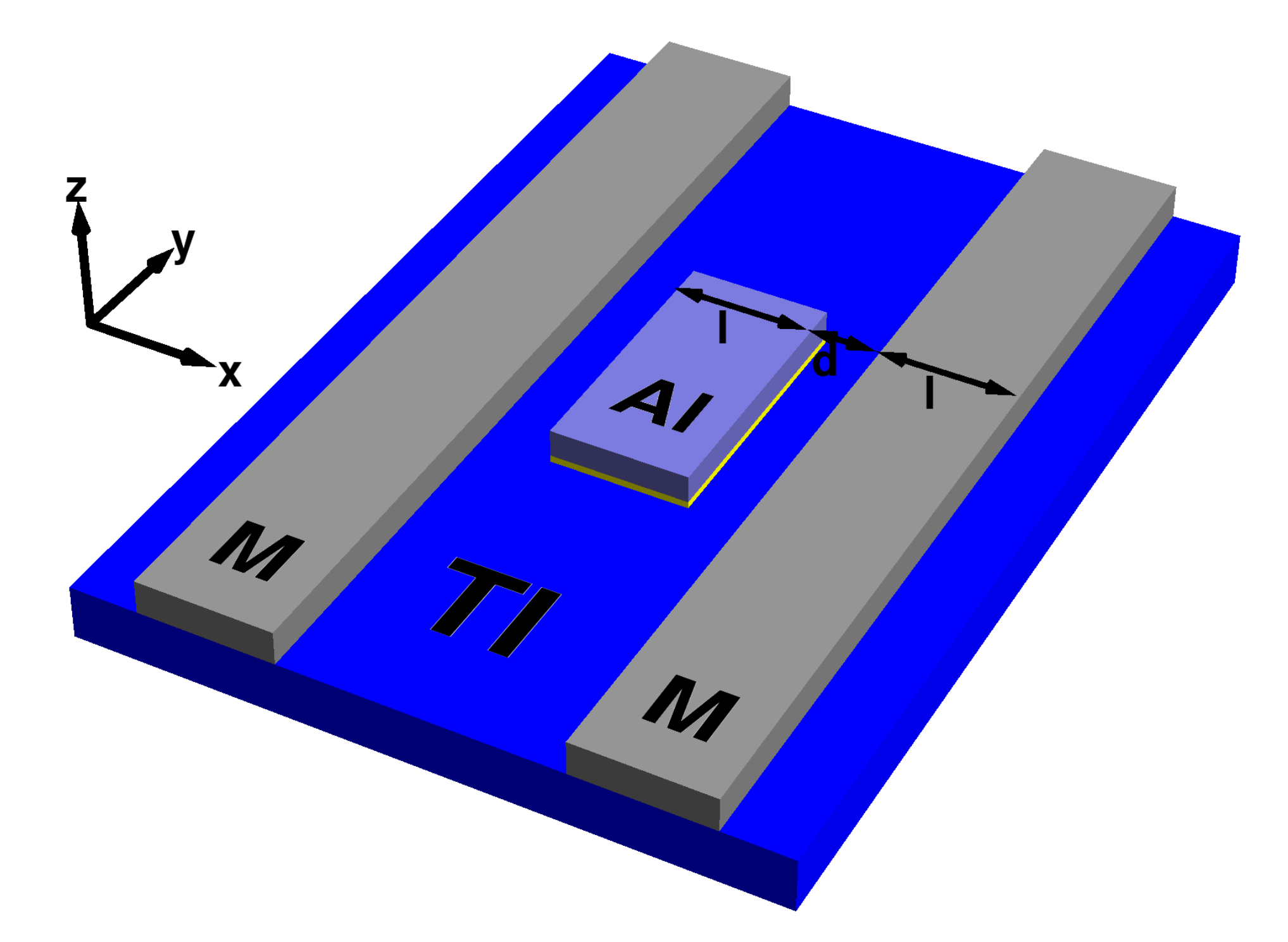
In the following we will provide theoretical calculations of the differential conductance of such a device and demonstrate that an extraction of the spin polarization is feasible.Dissertation In contrast to most ferromagnetic materials the density of states of the topological surface states varies strongly as a function of energy, which needs to be taken into account in the calculations. Also, the tunnelling conductance will depend on the spin-flip mean free path of the electrons in the topological surface states. In the presence of spin-flip scattering an electron that initially propagates in positive -direction can be scattered and eventually appear at the opposite electrode in negative -direction. For this reason the distance between the electrodes should be chosen smaller than a few spin-flip mean free paths to be able to extract the spin polarization. Experimental values for the spin-flip mean free path range between 200 nm in disordered Bi2Se3 Dufouleur and a few microns in HgTe Koenig2. In section III we will discuss this dependence on the spin-flip mean free path and show that it provides the possibility to extract the spin-flip mean free path from such devices.
II Model
To provide a realistic calculation of the tunnelling conductance of an Al/I/TI junction, we use a tight binding model for the Bi2Se3 class of materials as given in Ref. TMR. This tight binding model has been derived from bandstructure calculations up to third order in momentum by Liu et alLiu:PRB10 using theory. In -space the Hamiltonian can be written in terms of the Dirac matrices , where the Pauli matrices and act in orbital and spin space, respectively. It takes into account four dominant bands at the Fermi surface and reads
| (1) |
On a bilayer hexagonal lattice the tight-binding parameters can be defined as follows:Hao; TMR
The corresponding model parameters for Bi2Se3, which we consider here as an example, are derived from Liu et alLiu:PRB10 using the atomic distances and Zhang:APL09: , , , , , , , , and . The parameter adds only a tiny energy shift and will therefore be neglected in the following.
As regards the aluminum electrode, only its density of states near the Fermi level is of importance for the tunnelling current. Thus, for simplicity we describe the superconducting aluminum by Hamiltonian Eq. (1) with only one orbital and parameters , and . The parameter was chosen such that the center of the Al band fits the Fermi level of the TI. In this way the normal state density of states of the Al band is nearly constant within the bulk gap of the TI. The BCS density of states in the superconducting state is described by the Dynes formula, which accounts for a finite lifetime broadening in the aluminum: Dynes
| (2) |
Here, is energy, the electron magnetic moment, the applied magnetic field, the superconducting gap of Al, and . In order to calculate the transition rate of the junction, we Fourier-transform the Hamiltonian Eq. (1) into real space onto its lattice in -direction, i.e. in the direction perpendicular to the junction. Periodic boundary conditions are used in the in-plane directions which allows to keep the in-plane momenta and as good quantum numbers.
Using Fermi’s golden rule
| (3) |
for the transition rate from an initial state into a final state , the total tunnelling current from the Al film into the TI, which takes into account tunnelling processes at finite temperature in both directions, is given by
| (4) | |||||
for a bias voltage between the Al electrode and the TI. Here, and number the unperturbed eigenstates of the Al film and the TI, respectively. The Fermi function
| (5) |
describes the occupation of these states at finite temperature. The insulating barrier is modeled by a tunneling Hamiltonian of the form
| (6) |
where creates an electron in orbital with spin in the top layer of the topological insulator and destroys an electron in the bottom layer of the aluminum.
The differential conductance (DC) which is usually measured in experiments is obtained from the derivative of with respect to
| (7) | |||||
III Calculations
In this section we derive a method to calculate the polarization of the topological surface states from a given tunnel spectrum. As pointed out above we cannot simply take the differential conductance of an Al/I/TI junction but have to exploit the locking between spin and propagation direction. Concerning our calculations the propagation direction of an electron can be obtained via its group velocity . We first consider the device geometry shown in Fig. 2. Other geometries will be discussed in Appendix A.
In order to obtain useful approximation formulas for the differential conductance we start from an analytical approximation of the topological surface states, which is valid in the vicinity of the Dirac node. The results of this approximate calculation will be compared with full numerical results below. When we expand Hamiltonian Eq. (1) up to second order in , we can derive an analytical expression for the four components of the surface state wave function:TMR
| (8) |
Here, is for the upper and lower Dirac cone, is the in-plane polar angle of the momentum, is the degree of spin-polarization of the surface states, and the orientation of the spin is given by the phase , i.e. it is always rotated by with respect to . The corresponding eigenenergies only depend on the magnitude of the in-plane momentumTMR
| (9) |
These surface states describe an isotropic Dirac cone, i.e. they neglect the hexagonal deformation, which is of third order in . The position of the Dirac node is at the energy .
In our model for the Al electrode we simply have two degenerate eigenstates for each pair of and . The spatial dependence in -direction is a superposition of an incoming and a reflected wave and thus given by . An appropriate linear combination of these eigenstates then leads to states with a specific spin polarization. For a spin polarization within the - surface plane, this linear combination is given by
where is the in-plane polar angle of the polarization with respect to the -axis and
| (13) |
for given momenta and and energy . Using Eq. (8) and (III) with for the bottom layer of the aluminum, the transfer matrix element of the junction can be calculated
| (14) |
where is the hopping matrix element of the barrier. This can then be inserted into Eq. (7) multiplied with the shifted BCS density of states. To get the DC with respect to the electrode in positive -direction we follow Ref. TMR and introduce a function , which gives the probability that an electron initially propagating under an angle of ends up at this electrode. depends on the geometry of the device and can also be used to include effects like spin scattering in the TI. For the simple case shown in Fig. 2, where all electrons with a positive group velocity component in direction end up at that electrode it is simplyTMR
| (15) |
More complex cases are discussed in Appendix A. In the following we assume that is an even function, i.e. , which is always satisfied when mirror symmetry with respect to the --plane holds.
Let us choose the applied magnetic field to point in the direction of . Then, the differential conductance Eq. 7 consists of two contributions coming from the electrons with spin either parallel or antiparallel to the magnetic field. For the contribution with parallel spin we find
| (16) | |||||
| (17) | |||||
| (18) | |||||
Here, the DC becomes a product of a -integral, which depends on the geometry of the device and the relative polarization of the Al film with respect to the TI, and the term , which contains the densities of states of the two materials. Analogously, we find for electrons with spin oriented antiparallel
| (19) | |||||
with depending on instead of . The total DC of the junction is then
| (20) | |||||
| (21) | |||||
This is shown in Fig. 3 as a function of bias voltage for , , , , and a chemical potential of . The chemical potential is chosen somewhat below the Dirac node, i.e. at an energy where the hexagonal deformation of the Dirac-cone is small. For comparison, we also show the result of a numerical calculation of the differential conductance Eq. (7). This calculation was based on the full Hamiltonian Eq. (1) on a hexagonal lattice with layers along (). The momenta and were uniformly distributed over the first Brillouin zone with a discretization of and , corresponding to a sample width of about . In spite of the simplifications made in the analytical approximations, there is only a small deviation of the two DC curves. Please note that one can discern four peaks in the DC curves, even though the surface states are fully polarized here (). The physical reason for this is the spin texture of the topological surface states: even though the current from the Al electrode to the M electrode in positive -direction is dominated by spin up electrons, there is a small but finite probability that a spin down electron can tunnel into a topological surface state with positive group velocity in -direction.
In the following we demonstrate that the polarization of the topological surface states can be reliably inferred from such differential conductance curves. In Ref. TedrowMeservey-PRB7 Tedrow and Meservey derived a formula to extract the polarization of ferromagnets from the four peak heights of the DC curve. Here, we adapt that formula to the present case and show that the polarization can be obtained from it within a good approximation. If the density of states of the TI and Al film were constant as a function of energy except for the BCS density of states, we could express and in terms of the unsplit DC .TedrowMeservey-PRB7 Defining the differential conductance at some arbitrary bias voltage could be written
| (22) |
where is the splitting of spin up and spin down densities of states. One now evaluates at four bias voltages and , where is chosen at the peak position of the outermost peak. The values of the four conductances to (from left to right) are then given as
| (23) | |||||
| (24) | |||||
| (25) | |||||
| (26) |
Assuming that is a symmetric function of , this set of equations can be solved and the polarization can be obtained from the four conductances to leading to the formula
| (27) |
Here, the factor
| (28) |
accounts for the geometry of the device. For given by Eq. (15) we have .
Since we required that we can write the splitted DC curves Eq. (18) and (19) in terms of the unsplit curve in the derivation of Eq. (27), Eq. (27) becomes inaccurate if the densities of states of spin-up and spin-down electrons in the superconductor are not the same function of energy. This is the case if spin-orbit scattering in the superconductor is present. However, concerning thin aluminum films, spin-orbit scattering is small and the deviation from Eq. (27) should therefore be negligible.TedrowMeservey-PRB7 In the case of significant spin-orbit scattering in the superconductor, one can still fit the DC curves to obtain the polarization, if the energy dependence of the separate spin densities of states are known.
In the above calculation we assumed the normal state densities of states to be constant as a function of energy. Since this is not the case for TIs we have to remove this energy dependence from the measured DC in order to calculate the polarization . This can be done by fitting the DC curve with a low order polynomial , after cutting out the part with a high influence of the BCS density of states, as shown in Fig. 3 (dashed line). Afterwards one then multiplies with and analyzes this corrected DC curve.
The corrected DC curves are shown in Fig. 4. While there was a small difference between our analytical and numerical calculations in Fig. 3, the curves now agree very well and thereby support the general validity of this procedure and of Eq. (27). Because of the broadening of the BCS density of states, the exact peak maxima in general do not fulfill the symmetry requirement around . To reduce the error on the polarization value, the positions for the have to be chosen such that the slope of the DC at these positions is small. Here, we choose them such that the largest outer and largest inner peak, which are either and or and , are met exactly. The other two positions are then automatically given by the symmetry requirement around . Applying this to the analytical DC curve in Fig. 4 (black crosses) yields , consistent with the model parameter of . The deviation from the absolute value of the actual polarization of is only percentage points. It is however the inverse of the actual polarization for at the lower Dirac cone. The numerical DC curve yields , with only a slightly larger deviation. Applying the same formula, with the same factor, to the DC of the opposite metallic electrode, we find , i.e. the same value with opposite sign.
Equation (27) is based on the topological surface states given by Eq. (8) where the spin is always perpendicular to the in-plane momentum. As this may not always be the case it is useful to rewrite Eq. (27) such that it does not depend on the direction of the magnetic field but instead on the angular difference of magnetic field and surface state polarization. When we account for the counterclockwise rotation of the spin in the lower Dirac cone as well, the new model independent formula reads
| (29) |
Provided that the factor is calculated for a function that gives the probability with respect to the electrode in positive direction, it always yields the correct polarization value for surface electrons propagating to the considered electrode. In practice the magnetic field should be oriented parallel to the polarization of the TI (), i.e. such that the DC becomes maximal. By this, on the one hand we get the orientation of the surface state spin and on the other hand maximize the tunneling current. For , which is found for , Eq. (29) coincides with the formula of Tedrow and MeserveyTedrowMeservey-PRB7.
When we apply the above scheme to analytical DC curves for various polarization values, the difference between extracted polarization and actual polarization is always of the same order of magnitude, as shown in Fig. 5. There also seems to be no correlation between and .
In Fig. 6 we show the polarization extracted from DCs of the full Hamiltonian as a function of chemical potential . We see no systematic deviation from .
This is not intuitively clear considering the energy dependent hexagonal deformation of the Fermi surface along with an out of plane tilt of the spin polarization. To analyze the influence of a hexagonal deformation we therefore assume a correction of the surface state approximation, where the spin is tilted out of the surface plane with alternating sign with a threefold period:
| (30) |
Here, is the absolute value of the out of plane polarization. The spin expectation values of this improved approximation are given by
| (31) | |||||
| (32) | |||||
| (33) |
With this new approximation, the ratio of the DC peaks remains basically the same, with a new factor
| (34) |
which depends on . So it becomes possible to calculate the deviation from Eq. (29) for specified values of and estimate possible errors. For the case shown in Fig. 6 a maximal out-of-plane polarization of at the lower edge of the bulk gap yields a relative deviation for DC measurements along the -direction. This is only of the order of the measurement accuracy. Along the -direction (replace with ), this ratio is even slightly smaller , because the out-of-plane polarization is zero along the -axis and states close to the axis contribute strongest to the DC. In the extreme case of , which would be valid for a two dimensional device, these deviations become somewhat larger, but are still small. At the lower end of the bulk gap, a deviation of could be expected. Note, however that in this case, the out-of-plane polarization strongly depends on the measurement direction. Along some crystal axes it reaches the maximum value, while for others it completely vanishes. So, by varying the measurement direction, one can get rid of the out-of-plane spin component in order to access the in-plane component. It is however unlikely that the out-of-plane component can be determined from how varies as a function of . A device that is capable of measuring along certain crystal axes is presented in appendix A.3.
From Eq. (29) one sees that the polarization depends linearly on the geometrical factor . Instead of measuring for a given value of , one can alternatively also measure for a given . This grants access to another physical variable of the topological insulator: the spin-flip mean free path, which is crucial to applications in spintronics. The spin-flip mean free path is the average path after which an electron has lost information on its original spin and hence also on its propagation direction. If there is spin-scattering in the TI, the measured apparent spin-polarization of the surface states will depend on the length of the path between the Al and M electrode and the spin-flip mean free path thereby enters into the distance dependent factor. For the device in Fig. 2 we derived the probability distribution accounting for a finite spin-flip mean free path in Appendix A.1. From this expression can be calculated numerically. For a known polarization one can then simply calculate by fitting to Eq. (29). If is unknown, it is still possible to calculate from how varies with distance . However, this is more inaccurate as it requires multiple devices with different distances . To reduce errors, the different devices should at least be prepared on the same sample, since and may depend on the quality of the TI material. When we define the experimentally accessible quantity
| (35) |
is of the form
| (36) |
and identical for devices with different distances . Then, we can solve for the ratio of two :
| (37) |
The spin-flip mean free path can be fitted to this ratio as shown in Fig. 7. In order to get an accurate result, or, in the case of an unknown polarization, the distances , and should be in the same order of magnitude as .
IV Summary and Conclusions
We have studied a generalization of the Meservey-Tedrow method to topological insulators. Starting from an analytical approximation of TI surface states, we showed how quantum tunneling from a superconductor into these surface states can be used to measure their spin polarization. In contrast to the application to ferromagnets, one has to measure the tunneling current with respect to different spatial directions and take into account that the density of states in TI surface states is strongly energy dependent. Considering these aspects we derived formulas that allow easy calculation of the in-plane spin polarization from measured tunneling spectra, where the geometry of the device enters as a single factor. As there is no chemical potential dependence of the in-plane polarization, the tunneling spectra seem to be insensitive to the out-of-plane polarization of the surface states, at least for the device geometries considered here. When spin-flip scattering is included in the calculation of the geometrical factor, it can be measured as well and hence, if measured prior to the spin polarization, can increase the accuracy of the calculated spin polarization.
Acknowledgments
Financial support from the DFG via SPP 1666 “Topological Insulators” is gratefully acknowledged. We would like to thank A. Thomas and G. Reiss for valuable discussions.
Appendix A Geometrical factor
The geometrical factor plays a crucial role when calculating the spin polarization from a given DC curve. In this appendix we will therefore discuss the calculation of for some alternative geometries of the device. These geometries have some advantages over the basic geometry in Fig. 2, but are more difficult to realize. Considering the basic geometry in Fig. 2 we will also give a simple example of including the effect of spin-flip scattering in the TI. The function , from which is derived, gives the probability that an electron starting at an angle in the TI ends up at the considered metallic electrode. For a given value of it is hence given by the ratio of the number of all possible trajectories reaching the electrode and those not reaching it.
A.1 Basic geometry with spin-flip scattering
In the basic geometry in Fig. 2 it is assumed that all electrons initially moving in positive -direction will end up at the electrode at , which is only true as long as there is no spin-flip scattering. If is the spin-flip mean-free-path of the surface states, the distance between the aluminum and the metallic electrode and the width of these electrodes, is given by
| (38) | |||||
Here, is the distance between two vertical lines in the two electrodes and the integral averages over all . Note, that with spin-flip scattering also electrons initially moving in the opposite direction can reach the electrode. For small or large , approaches for all , i.e. all information on the initial spin is lost. In order to measure the spin from such a device the ratio should therefore be small. The geometrical factor has to be calculated numerically for specific values of , and (see Fig. 7).
A.2 Semi circles

The concept of electrodes with a semi circle form (Fig. 8) can be interesting if the spin-flip mean-free-path of the surface states is small, because in this geometry, the path length for electrons in the TI is small in all directions, reducing spin-flip processes. It also completely avoids possible scattering processes at the edges of the TI. For a given angle only electrons from a circular segment of the round Al electrode can reach the electrode in positive -direction and is then given by the ratio of this segment and the total area of the Al electrode:
| (39) | |||||
| (40) |
Here, and are the inner and outer radii of the spacing between aluminum (Al) and metallic (M) electrode, with being the distance between them. In the limit we get , while for the solution of the basic geometry is recovered.
A.3 U-shaped geometry

The device with a U-shaped metallic electrode (Fig. 9) discussed in Ref. TMR opens the possibility to investigate the spin-polarization of surface states with a specific momentum, because it filters out almost all electrons moving in other directions than that given by the two small electrodes. Hence, one could even apply it to anisotropic surfaces, where the Fermi surface is not circular and the spin-polarization may depend on the momentum direction. In this case is given byTMR
| (41) | |||||
where is the Heaviside step function, and are the length and height of the two small electrodes and the distance between them. For given values of , and , can be calculated numerically. If is large for all , Eq. (41) may be approximated by , i.e. . The DC then effectively becomes that of a two dimensional device, where all electrons reaching the metallic electrode have the same momentum direction and spin. In principle, using multiple devices with different orientations of the electrodes with respect to the lattice of the TI the -dependent spin structure of the surface states can be studied. It is also possible to split the U-shaped electrode into multiple parts. In this way measurements in multiple directions can be done with a single device.
References
- (1) B. A. Bernevig, T. L. Hughes, and S.-C. Zhang, Quantum Spin Hall Effect and Topological Phase Transition in HgTe Quantum Wells, Science 314, 1757 (2006).
- (2) L. Fu, C. L. Kane and E. J. Mele, Topological Insulators in Three Dimensions, Phys. Rev. Lett. 98, 106803 (2007).
- (3) M. König, S. Wiedmann, C. Brüne, A. Roth, H. Buhmann, L.W. Molenkamp, X.-L. Qi, and S.-C. Zhang, Quantum Spin Hall Insulator State in HgTe Quantum Wells Science 318, 766 (2007).
- (4) D. Hsieh, D. Qian, L. Wray, Y. Xia, Y. Hor, R.J. Cava, and M.Z. Hasan, A topological Dirac insulator in a quantum spin Hall phase, Nature (London) 452, 970 (2008).
- (5) Y. L. Chen, J. G. Analytis, J.-H. Chu, Z. K. Liu, S.-K. Mo, X. L. Qi, H. J. Zhang, D. H. Lu, X. Dai, Z. Fang, S. C. Zhang, I. R. Fisher, Z. Hussain, and Z.-X. Shen, Experimental Realization of a Three-Dimensional Topological Insulator, Bi2Te3, Science 325, 178 (2009).
- (6) Y. Tanaka, T. Yokoyama, and N. Nagaosa, Manipulation of the Majorana Fermion, Andreev Reflection, and Josephson Current on Topological Insulators, Phys. Rev. Lett. 103, 107002 (2009).
- (7) I. Garate and M. Franz, Inverse Spin-Galvanic Effect in the Interface between a Topological Insulator and a Ferromagnet, Phys. Rev. Lett. 104, 146802 (2010).
- (8) V. Krueckl and K. Richter, Switching Spin and Charge between Edge States in Topological Insulator Constrictions, Phys. Rev. Lett. 107, 086803 (2011).
- (9) M. Götte, T. Paananen, G. Reiss, and T. Dahm, Tunneling Magnetoresistance Devices Based on Topological Insulators: Ferromagnet–Insulator–Topological-Insulator Junctions Employing Bi2Se3, Phys. Rev. Applied 2, 054010 (2014).
- (10) M. Götte, M. Joppe, and T. Dahm, Pure spin current devices based on ferromagnetic topological insulators, Sci. Rep. 6, 36070 (2016).
- (11) J. Han, A. Richardella, S.A. Siddiqui, J. Finley, N. Samarth, and L. Liu, Room-Temperature Spin-Orbit Torque Switching Induced by a Topological Insulator, Phys. Rev. Lett. 119, 077702 (2017).
- (12) N. H. D. Khang, Y. Ueda, and P. N. Hai, A conductive topological insulator with large spin Hall effect for ultralow power spin-orbit torque switching, Nat. Mat. 17, 808 (2018).
- (13) M. He, H. Sun, and Q. L. He, Topological Insulator: Spintronics and Quantum Computation, Front. Phys. 14, 43401 (2019)
- (14) C.-X. Liu, X.-L. Qi, H.J. Zhang, X. Dai, Z. Fang, and S.-C. Zhang, Model Hamiltonian for topological insulators, Phys. Rev. B 82, 045122 (2010).
- (15) S. Souma, K. Kosaka, T. Sato, M. Komatsu, and A. Takayama, Direct Measurement of the Out-of-Plane Spin Texture in the Dirac-Cone Surface State of a Topological Insulator, Phys. Rev. Lett. 106, 216803 (2011).
- (16) O. V. Yazyev, J. E. Moore, and S. G. Louie, Spin Polarization and Transport of Surface States in the Topological Insulators Bi2Se3 and Bi2Te3 from First Principles, Phys. Rev. Lett. 105, 266806 (2010).
- (17) X. Wang, G. Bian, T. Miller, and T.-C. Chiang, Topological spin-polarized electron layer above the surface of Ca-terminated Bi2Se3, Phys. Rev. B 87, 035109 (2013).
- (18) J. Sanchez-Barriga et al, Photoemission of Bi2Se3 with Circularly Polarized Light: Probe of Spin Polarization or Means for Spin Manipulation?, Phys. Rev. X 4, 011046 (2014).
- (19) Z.-H. Pan, E. Vescovo, A. V. Fedorov, D. Gardner, Y. S. Lee, S. Chu, G. D. Gu, and T. Valla, Electronic Structure of the Topological Insulator Bi2Se3 Using Angle-Resolved Photoemission Spectroscopy: Evidence for a Nearly Full Surface Spin Polarization, Phys. Rev. Lett. 106, 257004 (2011).
- (20) C. Jozwiak, Y. L. Chen, A. V. Fedorov, J. G. Analytis, C. R. Rotundu, A. K. Schmid, J. D. Denlinger, Y.-D. Chuang, D.-H. Lee, I. R. Fisher, R. J. Birgeneau, Z.-X. Shen, Z. Hussain, and A. Lanzara, Widespread spin polarization effects in photoemission from topological insulators, Phys. Rev. B 84, 165113 (2011).
- (21) G. Landolt, S. Schreyeck, S. V. Eremeev, B. Slomski, S. Muff, J. Osterwalder, E. V. Chulkov, C. Gould, G. Karczewski, K. Brunner, H. Buhmann, L. W. Molenkamp, and J. H. Dil, Spin Texture of Bi2Se3 Thin Films in the Quantum Tunneling Limit,Phys. Rev. Lett. 112, 057601 (2014).
- (22) C.-H. Park and S. G. Louie, Spin Polarization of Photoelectrons from Topological Insulators, Phys. Rev.Lett. 109, 097601 (2012).
- (23) R. Meservey and P. M. Tedrow, Spin-Dependent Tunneling into Ferromagnetic Nickel, Phys. Rev. Lett. 26, 192 (1971).
- (24) R. Meservey and P. M. Tedrow, Spin Polarization of Electrons Tunneling from Films of Fe, Co, Ni, and Gd, Phys. Rev. B 7, 318 (1973).
- (25) R. Meservey, P. M. Tedrow and P. Fulde, Magnetic Field Splitting of the Quasiparticle States in Superconducting Aluminum Films, Phys. Rev. Lett. 25, 1270 (1970).
- (26) M. Götte, Topological insulator based spintronics: Theoretical investigation of pure spin current devices and polarization measurements, Universität Bielefeld, Bielefeld (2017), urn:nbn:de:0070-pub-29128707
- (27) J. Dufouleur, L- Veyrat, B. Dassonneville, C. Nowka, S. Hampel, P. Leksin, B. Eichler, O. G. Schmidt, B. Büchner, and R. Giraud, Enhanced Mobility of Spin-Helical Dirac Fermions in Disordered 3D Topological Insulators, Nano Lett. 16, 6733 (2016).
- (28) M. König, H. Buhmann, L. W. Molenkamp, T. Hughes, C.-X. Liu, X.-L. Qi, and S.-C. Zhang, The Quantum Spin Hall Effect: Theory and Experiment J. Phys. Soc. Japan 77, 031007 (2008).
- (29) L. Hao and T. K. Lee, Surface spectral function in the superconducting state of a topological insulator, Phys. Rev. B 83, 134516 (2011).
- (30) G. Zhang, H. Qin, J. Teng, J. Guo, Q. Guo, X. Dai, Z. Fang, and K. Wu, Quintuple-layer epitaxy of thin films of topological insulator Bi2Se3, Appl. Phys. Lett. 95, 053114 (2009).
- (31) R. C. Dynes, V. Narayanamurti, and J. P. Garno, Direct Measurement of Quasiparticle-Lifetime Broadening in a Strong-Coupled Superconductor, Phys. Rev. Lett. 41, 1509 (1978).
- (32) O. Schebaum, D. Ebke, A. Niemeyer, G. Reiss, J. S. Moodera, A. Thomas, Direct measurement of the spin polarization of Co2FeAl in combination with MgO tunnel barriers, J. Appl. Phys. 107, 09C717 (2010).