NITEP 28
Dark matter signals on a laser interferometer
Abstract
WIMPs are promising dark matter candidates. A WIMP occasionally collides with a mirror equipped with interferometric gravitational wave detectors such as LIGO, Virgo, KAGRA and the Einstein Telescope (ET). When WIMPs collide with a mirror of an interferometer, we expect that characteristic motions of the pendulum and mirror are excited, and those signals could be extracted by highly sophisticated sensors developed for gravitational wave detection. We analyze the motions of the pendulum and mirror, and estimate the detectability of these motions. For the “Thin-ET” detector, the signal-to-noise ratio may be , where is the mass of a WIMP. We may set a more strict upper limit on the cross section between a WIMP and a nucleon than the limits obtained by other experiments so far when is approximately lower than 0.2 GeV. We find an order-of-magnitude improvement in the upper limit around .
pacs
95.35.+d, 04.30.-w, 04.80.NnI Introduction
The first direct detection of a gravitational wave (GW) event was achieved by LIGO (Laser Interferometer Gravitational-Wave Observatory) in 2015 GW150914. To date, ten binary black hole mergers GW150914; GW151226; GW170104; GW170814; GW170608; GWBBHs and one binary neutron star signal GW170817 were detected in the first and second LIGO/Virgo observing runs (O1, O2). LIGO and Virgo started the third observing run (O3) in April 2019. KAGRA, the first cryogenic underground GW observatory, is now under construction in Japan KAGRA1; KAGRA2; KAGRA3; KAGRA4, and it is planned to join the O3 run. In addition, the third-generation GW detectors such as Einstein Telescope (ET) ETcqrg and Cosmic Explorer CE are being proposed. As the sensitivities of the current-generation GW detectors are so high, these detectors can be sensitive not only to GWs, but also to external agents. Namely, GW detectors could extract signals caused by dark matter particles colliding with a mirror equipped with interferometers.
Candidates for dark matter may be categorized into two types. One is macroscopic matter, such as MACHOs (massive compact halo objects), whereas the other is microscopic matter, such as WIMPs (weakly interacting massive particles). WIMPs are believed to be good candidates for dark matter to explain the structure of the present Universe, and have an extensive allowed mass range of about 0.1 GeV to 10 TeV. Methods explored so far to hunt for WIMPs include collider searches, indirect detections, and direct detections: for details, see, e.g., Refs. Gelmini; BiYui. To prove the existence of WIMPs, direct detections, where one observes possible nuclear recoils after WIMP-nucleon elastic scattering, would be the most suitable method. The cross section between a WIMP and a nucleon is expected to be extremely small. So far, a couple of research groups have reported positive signals DAMA; CDMS; CoGeNT, but the results are still controversial and it seems still premature to claim the existence of a WIMP.
We propose a search method for WIMP signals using laser interferometric gravitational wave detectors. Possible dark matter signals on laser interferometers have been investigated in several works Kashlinsky2016; Aoki; Yamamoto; Guo. However, calculations of the signals caused by direct interaction between a WIMP and nucleons in the mirror of interferometers have not been considered in the literature yet.
In this paper, we solve equations of motion for the behavior of the pendulum and mirror induced by a WIMP collision with the mirror, and obtain the characteristic amplitude spectrum. Then, we derive the signal-to-noise ratio by comparing the signals to the design sensitivity of each detector, and set an upper limit on the cross section between a WIMP and a nucleon.
II Dark matter flux and event rate
The dark matter flux, , around the Earth is given as follows Baudis2012:
| (1) | |||||
where is the number density of WIMPs, is the mean velocity of WIMPs, is the local dark matter density, and is the mass of WIMPs. Using this flux, we can estimate the event rate, , of WIMP collisions with nucleons near the Earth as follows:
| (2) | |||||
where is the Avogadro constant, is the molar mass of the target nucleus, and is the cross section between a WIMP and a nucleon. The value of the cross section may affect the lifetime of WIMPs; thus, the evaluation of the cross section could play a important role to elucidate the nature of WIMPs.
III Expected Dark Matter Signals
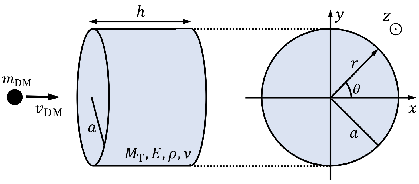
The schematic image for a collision of a WIMP with the mirror is shown in Fig. 1. The parameters , , , , , and in Fig. 1 are the mass, Young’s modulus, matter density, Poisson’s ratio, radius, and thickness of the mirror, respectively. The values of these parameters for the detectors are given in Table 1. When a WIMP collides with a nucleon in the mirror, we expect that various characteristic motions of the pendulum and mirror occur. In this paper, we consider the induced signals due to (i) pendulum (translation) motion and (ii) elastic oscillation of the mirror. We do not consider other motions such as the rotation of the mirror or the violin mode of the pendulum, and so on. Here, we derive the expressions for signals due to (i) and (ii).
(i) Pendulum (translation) motion: First, we consider the translation of the mirror, namely the motion of the pendulum. The equation of motion for this mode is given by
| (3) |
where is the quality factor, is the resonance frequency of the pendulum, and is the external force given by a WIMP collision:
| (4) |
where is the momentum of a WIMP, is the typical velocity of WIMPs, and we assume the collision happens at . Here, we assume the delta-functional force for . When a WIMP that has collides with a nucleon in the mirror and scatters elastically, the nucleon will have a kinetic energy of about . This energy may be higher than the binding energy of intermolecular force in the mirror, so the nucleon would give rise to a “secondary” nucleon. By using the SRIM (the Stopping and Range of Ions in Matter) calculation tool SRIM, we can show that the secondary nucleon may be stopped within about , and this timescale is much shorter than the sampling time of gravitational wave data acquisition systems. Thus, we can ignore the effect of the secondary nucleon, and we can approximately describe the collision using a delta function as in Eq. (4).
The solution of the equation of motion (3) is obtained as in a damped sinusoidal waveform:
| (5) |
Using Fourier transformation, defined as , this solution can be written in the frequency domain as follows:
| (6) |
This expression shows that the signal caused by the motion of the pendulum has a sharp peak at the resonance frequency , and the signal is proportional to at higher frequencies than .
| Laser Interferometers | |||
| KAGRA | LIGO, Virgo | Einstein Telescope | |
| Material | Sapphire | Fused Silica | Fused Silica |
| Molar mass, | 101.96 | 60.08 | 60.08 |
| Mirror Mass, | 23 | 40 | 200 |
| Density, | 4.00 | 2.20 | 2.20 |
| Radius, | 11 | 17.5 | 31 |
| Thickness, | 15 | 20 | 30 |
| Young’s modulus, | 400 | 72.6 | 72.6 |
| Poisson’s ratio, | 0.3 | 0.16 | 0.16 |
(ii) Elastic oscillation of the mirror: Second, we consider the elastic oscillation of the mirror induced by a WIMP collision with the mirror that has a cylindrical shape. The equation of motion is given by
| (7) |
where is the flexural rigidity, is the quality factor of the mirror, is the eigenfrequency of the elastic oscillation, and is the two-dimensional Laplacian. The solution of Eq. (7) is given by
| (8) |
where corresponds to the number of nodal diameters, is the number of nodal circles, denotes the eigenfrequency for each mode, is a numerical constant depending on initial conditions, and is a function of , which will be given below.
As for the boundary condition, we assume that the mirror is a completely free cylinder, since the mirror is not clamped. In this situation, at the edge of the circle of the cylinder, , the bending moment and shearing force should be zero—that is, they satisfy the following conditions:
| (9) |
These boundary conditions lead to the eigenvalue equation
| (10) |
where , , is a Bessel function, is a modified Bessel function, , and . From these relations, we obtain the eigenfrequency for each mode, and these frequencies are listed in Table 2. As can be expected, the eigenfrequency of each mode is smaller for a softer and thinner mirror. The material of the mirrors equipped with the KAGRA is sapphire, which is harder than the fused silica that constitutes the mirrors of LIGO and Virgo, so the eigenfrequency of each mode for KAGRA is higher than that for the other mirrors. On the other hand, the mirrors for ET are relatively thinner than the mirrors for KAGRA, LIGO and Virgo; thus, the mirrors for ET have a lower eigenfrequency for each mode.
| — | — | 3.20 (1.01) [0.481] | 7.43 (2.31) [1.10] | 13.0 (4.03) [1.93] | 20.0 (6.15) [2.94] | |
| 5.38 (1.51) [0.724] | 12.2 (3.54) [1.69] | 21.1 (6.17) [2.95] | 31.6 (9.33) [4.46] | 43.9 (13.0) [6.20] | 57.8 (17.1) [8.17] | |
| 23.0 (6.66) [3.18] | 35.7 (10.4) [4.97] | 50.4 (14.7) [7.04] | 66.8 (19.6) [9.36] | 85.0 (25.0) [11.9] | 105 (30.8) [14.7] | |
| 52.4 (15.3) [7.30] | 71.0 (20.7) [9.91] | 91.5 (26.8) [12.8] | 114 (33.3) [15.9] | 138 (40.4) [19.3] | 164 (48.0) [22.9] | |
| 93.6 (27.3) [13.1] | 118 (34.5) [16.5] | 145 (42.2) [20.2] | 173 (50.5) [24.1] | 203 (59.3) [28.3] | 234 (68.6) [32.8] | |
| 147 (42.8) [20.5] | 177 (51.7) [24.7] | 209 (61.2) [29.2] | 243 (71.2) [34.0] | 279 (81.7) [39.0] | 317 (92.7) [44.3] |
Then, we derive the displacement of the mirror and function by using Eqs. (III) and (10), so the solution of Eq. (7) is written as
| (11) |
Using Fourier transformation, we obtain the displacement in the frequency domain as
| (12) |
Thus, the signal caused by elastic oscillation also has sharp peaks at the resonance frequencies . To calculate , we consider the momentum conservation law that is given by
| (13) |
where means the collision point of the WIMP on the mirror. We multiply for both sides, and integrate over the entire region of the mirror surface, obtaining
| (14) |
We note that the modes that contribute to the displacement at the center of the circle of the mirror should play a key role in evaluating the effects of the signals caused by a WIMP collision, since laser beams used for measuring the differential displacement of the arm length irradiate the center of the circle of the mirror. Thus, hereafter, we only consider the elastic oscillations at the center of the circle that correspond to modes.
We derive the numerical factor for each mode as follows:
| (15) |
Using , we obtain the magnitude of the displacement at and for each mode and as follows:
| (16) |
The values of them are summarized in Table 3 with . When a WIMP collides with the mirror at the center of the circle (), the displacement attains the maximum for each mode.
| The collision point of the WIMP on the mirror, | ||||||
| 60.8 (404) [376] | 59.2 (394) [366] | 54.4 (363) [337] | 46.8 (312) [290] | 36.7 (246) [229] | 24.6 (166) [155] | |
| 8.19 (52.4) [48.8] | 7.42 (47.6) [44.2] | 5.35 (34.4) [32.0] | 2.54 (16.5) [15.4] | 0.23 (1.19) [1.11] | 2.25 (14.2) [13.2] | |
| 2.34 (14.9) [13.8] | 1.86 (11.8) [11.0] | 0.70 (4.44) [4.13] | 0.44 (2.79) [2.60] | 0.94 (5.98) [5.56] | 0.65 (4.15) [3.85] | |
| 0.98 (6.19) [5.76] | 0.63 (4.00) [3.72] | 0.05 (0.31) [0.28] | 0.39 (2.49) [2.31] | 0.17 (1.09) [1.01] | 0.21 (1.33) [1.24] | |
| 0.50 (3.15) [2.93] | 0.24 (1.50) [1.39] | 0.15 (0.95) [0.88] | 0.13 (0.85) [0.79] | 0.11 (0.68) [0.63] | 0.10 (0.66) [0.61] | |
| — | ||||||
| 11.3 (77.4) [72.0] | 2.87 (17.3) [16.1] | 17.2 (114) [106] | 31.4 (211) [197] | 45.1 (307) [285] | ||
| 3.04 (19.4) [18.0] | 2.50 (16.1) [14.9] | 0.88 (5.83) [5.42] | 1.35 (8.44) [7.85] | 3.72 (23.9) [22.2] | ||
| 0.06 (0.36) [0.34] | 0.60 (3.75) [3.49] | 0.55 (3.48) [3.23] | 0.05 (0.28) [0.26] | 0.87 (5.50) [5.11] | ||
| 0.26 (1.65) [1.54] | 0.02 (0.14) [0.13] | 0.23 (1.43) [1.33] | 0.07 (0.43) [0.40] | 0.31 (1.98) [1.84] | ||
| 0.09 (0.56) [0.52] | 0.09 (0.56) [0.52] | 0.07 (0.46) [0.42] | 0.06 (0.39) [0.36] | 0.14 (0.90) [0.84] | ||
IV Limit on the Cross Section between a WIMP and a Nucleon
Here, we calculate the signal-to-noise ratio (SNR) and estimate the upper limit on the cross section between a WIMP and a nucleon . To calculate the SNR, we introduce the characteristic amplitude spectrum that is defined by
| (17) |
where the square modulus of the amplitude is given by , and is the arm length of an interferometer. Using the spectrum , the SNR is given by
| (18) |
where is the one-sided power spectral density of the detector in consideration that includes resident and possible backgrounds such as a seismic noise, radiation pressure noise, shot noise, thermal noise, etc. Here and are the minimum and the maximum frequencies of the design sensitivity curves for the detectors given in Refs. LIGOsens; KAGRAsens. As mentioned above, the signal spectrum has sharp peaks at the eigenfrequencies and small values for other frequency regions, so the contributions of the peaks predominantly increase the SNR. However, most of the eigenfrequencies for KAGRA, LIGO, Virgo, and ET are outside of the sensitivity curves for the detectors; thus the SNR cannot attain enough values to detect these signals.
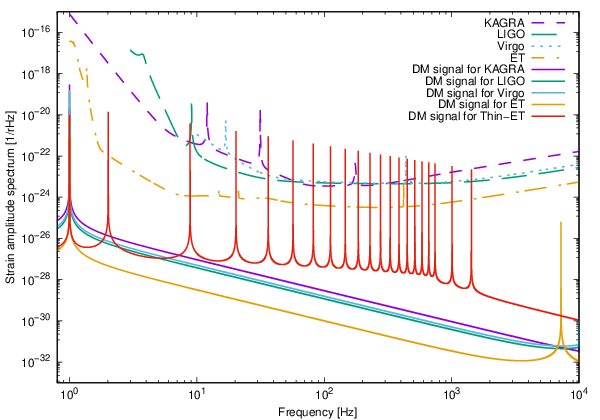
Alternatively, we can propose a “Thin-ET” detector to extract the signal caused by a WIMP collision. Mirrors of the Thin-ET detector would have thinner thickness () and larger radius (), and the other parameters of the mirrors and the arm length are the same as those of the ET detector. Thus, the sensitivity curve of the Thin-ET detector would be the same as that of ET by using the calculation in Ref. CA. Since the thin-thickness and large-radius cylinder has low eigenfrequencies, the many sharp peaks can be in the observation frequency band. Thus, we expect that we can obtain a larger SNR for the Thin-ET detector than the SNRs for other interferometers. The characteristic amplitude spectra and design sensitivities for the existing or planned interferometers dedicated for gravitational wave observations are shown in Fig. 2. This figure indicates that most of the peak magnitudes at the eigenfrequencies for the Thin-ET detector may be higher than the given sensitivity curve, so we expect that the Thin-ET detector has a moderate SNR value. From the above calculation, the SNR is proportional to mass of a WIMP, so we can write the SNR as , where for the Thin-ET detector.
Since we know the expected waveform of the dark matter signal considered in this paper, it is most optimal to detect the signal using a detection statistic based on the matched filtering technique, which is widely used in the gravitational wave data analysis community. We declare signal detection if our detection statistic exceeds, say, . If not, we conclude no detection and proceed to set an upper limit on the cross section between a WIMP and a nucleon.
The number of collision events follows a Poisson distribution with the expected number of events given by , where is the detection efficiency and is the observation time. The detection efficiency may be calculated based on the detection threshold on our detection statistic (), the expected signal-to-noise ratio given by Eq. (18), and the statistical property of detector noise. We assume that the noise of a laser interferometric gravitational wave detector follows a stationary Gaussian distribution, which is a good approximation to the first order. The upper limit on the event rate at a 90% confidence level, , may then be calculated using
| (19) |
Using Eq. (19), we obtain the upper limit on the cross section as follows:
| (20) |
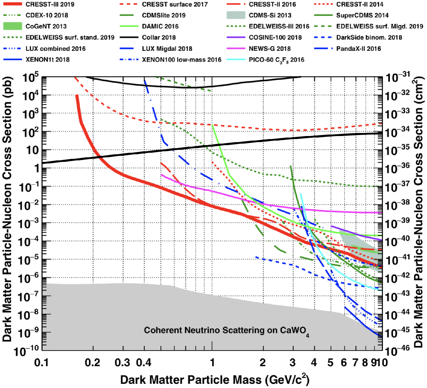
where the local dark matter density and the mean velocity of WIMPs are fixed at and , respectively. The last two factors in Eq. (20) mean the ratio between the surface area of two bottom faces and the total surface area of the mirror. Our possible upper limit on the cross section as a function of the WIMP mass, along with those by other experiments, is shown in Fig. 3. This figure implies that, in the low-WIMP-mass region (), we could set more strict upper limits on the cross section than the limits obtained so far. When the mass of the WIMP is just a little smaller than 0.2 GeV, the upper limit would be improved by roughly an order of magnitude.
We note that we should consider the effects of instrumental noises and have to distinguish target signals from these noises when we analyze real data obtained by interferometric gravitational wave detectors. Possible sources of such noises include the collisions of ambient particles with a mirror and thermal fluctuation of the mirror. The process to estimate the effect of the former noise will be given in Appendix A. As a result, the magnitude of the strain equivalent noise amplitude may be . This scale is smaller than other noises, which are already included in of Eq. (18), as can be seen from Fig. 2; thus, the noise induced by the collisions of ambient particles with the mirror does not have a critical influence on our analysis. On the other hand, the latter noise would excite eigenmodes with eigenfrequencies that are the same as the peak frequencies induced by collisions of the dark matter. However, the “effective temperature”, which characterizes the effect of thermal noise, can be lowered to by applying a filter that has an optimal time length. Thus, by using the filter, we may be able to distinguish the dark matter signals from the thermal noise, and we can extract the signals efficiently. Cosmic rays give rise to signals similar to what we consider in this paper, but the energy scale is sufficiently smaller than the sensitivity of the detector, as is discussed in Ref. Yamamoto. Thus, it may not affect our analysis. Detailed discussions and estimations including such instrumental noises and other possible motions of the pendulum and mirror would be considered in future works.
V Conclusion
When dark matter particles, such as WIMPs, collide with a mirror equipped with interferometers, the motion of a pendulum and the elastic oscillation of the mirror are excited. We performed a mode analysis of possible signals caused by a WIMP collision with the mirror and calculated the signal-to-noise ratio, considering the design sensitivities of the existing or planned detectors and the Thin-ET detector. We derived that the signal-to-noise ratio may be for the Thin-ET detector, and we then estimated the upper limit on the cross section between a WIMP and a nucleon. Such a Thin-ET detector enables us to set more strict upper limits on the cross section in the low-WIMP-mass region () that has never been explored before. The limit would be improved by an order of magnitude around .
*
Appendix A Estimation for an effect of ambient particles
Optical components of a laser interferometric gravitational wave detector are in an ultrahigh vacuum of torr. The collisions of ambient particles with a mirror may frequently occur and become a noise for the target signals. Here, we estimate the effect of this noise as follows.
The collision rate of the ambient particles, , is given by
| (21) |
where is the number density, denotes the mean velocity, is the mass of the ambient particles, is the air pressure, is the temperature in the vacuum chamber, is the Boltzmann constant, and corresponds to the surface area of two bottom faces of a mirror. By substituting characteristic values for these parameters, we can estimate the collision rate as
| (22) |
An impulse received by each collision of a particle, , is given by
| (23) |
We assume that the number of collisions of the ambient particles with the mirror follows the Poisson distribution, and then the fluctuation of the rate, , can be expressed as . Thus, the strain equivalent noise amplitude induced by the collisions of ambient particles, , is given by
| (24) | |||||
For the Thin-ET detector, becomes , and this scale is smaller than other noises, as can be seen from Fig. 2.
References
- (1) B. P. Abbott (LIGO Scientific and Virgo Collaborations), Phys. Rev. Lett. 116, 061102 (2016).
- (2) B. P. Abbott (LIGO Scientific and Virgo Collaborations), Phys. Rev. Lett. 116, 241103 (2016).
- (3) B. P. Abbott (LIGO Scientific and Virgo Collaborations), Phys. Rev. Lett. 118, 221101 (2017); 121, 129901(E) (2018).
- (4) B. P. Abbott (LIGO Scientific and Virgo Collaborations), Phys. Rev. Lett. 119, 141101 (2017).
- (5) M. Fishbach and D. E. Holz (LIGO Scientific and Virgo Collaborations), Astrophys. J. Lett. 851, L25 (2017).
- (6) B. P. Abbott (LIGO Scientific and Virgo Collaborations), Phys. Rev. X 9, 031040 (2019).
- (7) B. P. Abbott (LIGO Scientific and Virgo Collaborations), Phys. Rev. Lett. 119, 161101 (2017).
- (8) T. Akutsu (KAGRA Collaboration), Prog. Theor. Exp. Phys. 2018, 013F01 (2018).
- (9) T. Akutsu (KAGRA Collaboration), Classical Quantum Gravity 36, 165008 (2019).
- (10) T. Akutsu (KAGRA Collaboration), Nat. Astron. 3, 35 (2019).
- (11) K. Akiyama (KAGRA Collaboration), Classical Quantum Gravity 36, 095015 (2019).
- (12) M. Punturo , Classical Quantum Gravity 27, 194002 (2010).
- (13) B. P. Abbott (LIGO Scientific and Virgo Collaborations), Classical Quantum Gravity 34, 044001 (2017).
- (14) G. B. Gelmini, arXiv:hep-ph/1502.01320 (2015).
- (15) X. J. Bi, P. F. Yui, and Q. Yuan, Front. Phys. 8, 794 (2013).
- (16) R. Bernabei (DAMA Collaboration), Euro. Phys. J. C 56, 333 (2008).
- (17) R. Agnese (SuperCDMS Collaboration), Phys. Rev. Lett. 112, 241302 (2014).
- (18) C. E. Aalseth (CoGeNT Collaboration), Phys. Rev. D 88, 012002 (2013).
- (19) A. Kashlinsky, Astrophys. J. Lett. 823, L25 (2016).
- (20) A. Aoki and J. Soda, Int. J. Mod. Phys. D 26, 1750063 (2017).
- (21) K. Yamamoto , Phys. Rev. D 78, 022004 (2008).
- (22) H.-K. Guo , Communications Physics 2, 155 (2019).
- (23) L. Baudis, Phys. Dark Universe 1, 94 (2012).
- (24) SRIM (The Stopping and Range of Ions in Matter), http://www.srim.org.
- (25) LIGO Document, No. LIGO DCC T1500293-v11, https://dcc.ligo.org/LIGO-T1500293-v11/public.
- (26)
KAGRA Document,
No. JGW-T1707038,
https://gwdoc.icrr.u-tokyo.ac.jp/DocDB/0070/T1707038/007/spectrum_DRSE.txt. - (27) J. D. E. Creighton and W. G. Anderson, Gravitational-Wave Physics and Astronomy: An Introduction to Theory, Experiment and Data Analysis, Wiley-VCH, Weinheim (2011).
- (28) A. H. Abdelhameed (CRESST Collaboration), Phys. Rev. D 100, 102002 (2019).
- (29) G. Angloher (CRESST Collaboration), Euro. Phys. J. C 76, 25 (2016).
- (30) G. Angloher (CRESST Collaboration), Euro. Phys. J. C 77, 637 (2017).
- (31) H. Jiang (CDEX Collaboration), Phys. Rev. Lett. 120, 241301 (2018).
- (32) R. Agnese (SuperCDMS Collaboration), Phys. Rev. D 99, 062001 (2019).
- (33) A. Aguilar-Arevalo (DAMIC Collaboration), Phys. Rev. D 94, 082006 (2016).
- (34) L. Hehn , Euro. Phys. J. C 76, 548 (2016).
- (35) E. Armengaud (EDELWEISS Collaboration), Phys. Rev. D 99, 082003 (2019).
- (36) R. Agnese (SuperCDMS Collaboration), Phys. Rev. Lett. 112, 241302 (2014).
- (37) C. E. Aalseth (CoGeNT Collaboration), Phys. Rev. D 88, 012002 (2013).
- (38) P. Agnes (DarkSide Collaboration), Phys. Rev. Lett. 121, 081307 (2018).
- (39) D. S. Akerib (LUX Collaboration), Phys. Rev. Lett. 118, 021303 (2017).
- (40) D. S. Akerib (LUX Collaboration), Phys. Rev. Lett. 122, 131301 (2019).
- (41) X. Cui (PandaX-II Collaboration), Phys. Rev. Lett. 119, 181302 (2017).
- (42) E. Aprile (XENON Collaboration), Phys. Rev. D 94, 092001 (2016).
- (43) E. Aprile (XENON Collaboration), Phys. Rev. Lett. 121, 111302 (2018).
- (44) G. Adhikari (The COSINE-100 Collaboration), Nature (London) 564, 83 (2018).
- (45) J. I. Collar, Phys. Rev. D 98, 023005 (2018).
- (46) Q. Arnaud , Astropart. Phys. 97, 54 (2018).
- (47) C. Amole (PICO Collaboration), Phys. Rev. D 93, 052014 (2016).
- (48) A. Gütlein , Astropart. Phys. 69, 44 (2015).