Security-Aware Access Model for Data-Driven EHR System
Abstract
Digital Healthcare systems are very popular lately, as they provide a variety of helpful means to monitor people’s health state as well as to protect people against an unexpected health situation. These systems contain a huge amount of personal information in a form of electronic health records that are not allowed to be disclosed to unauthorised users. Hence, health data and information need to be protected against attacks and thefts. In this paper, we propose a secure distributed architecture for healthcare data storage and analysis. It uses a novel security model to rigorously control permissions of accessing sensitive data in the system, as well as to protect the transmitted data between distributed system servers and nodes. The model also satisfies the NIST security requirements. Thorough experimental results show that the model is very promising.
Index Terms:
Healthcare system, Electronic Health Record (EHR), Kerberos, LDAP, Symmetric Key Scheme, Public Key Scheme, Hash Function, SSL/TLS.I Introduction
E-Healthcare systems are very popular in recent years, as it becomes a matter of urgency to manage and control patients’ data. This data can be used to support them in bad health and emergency situations, to evaluate practitioner performance, or to operate as a health-caring consultant11 1 How Health Care Analytics Improves Patient Care, https://healthinformatics.uic.edu/blog/how-health-care-analytics-improves-patient-care/ as well. Hence, users find the most of healthcare applications and devices helpful. In order to predict and support patients well-being, their data should be collected and stored in a form of electronic health records (EHR). However, as patients’ data is very sensitive and must be protected against leakage and attacks, the patients do not trust e-healthcare systems. For instance, Orange telecommunication provider declared that of users did not trust companies in the way their data was used.22 2 Rethinking Personal Data: Trust and Context in User-Centred Data Ecosystems, http://www3.weforum.org/docs/WEF_RethinkingPersonalData_TrustandContext_Report_2014.pdf. Therefore, users’ trust has been raised, as their personal data must be protected and processed in a secret way against possibilities of being unexpectedly disclosed. Moreover, increasing user’s trust will surely guarantee the sustainability of the potential data-driven economy.
To protect patients’ data against any abusive use or attacks, several international regulations [8] have been issued, such as the US Health Insurance Portability and Accountability Act (HIPAA), the Health Information Technology for Economic and Clinical Health (HITECH), the European Union’s Data Protection Directive, the Australian Privacy Act and Japan’s Personal Information Protection Act (PIPA). These regulations set policies on data access to the health information in the majority regions of the world. However, they do not protect personal data directly against all vulnerabilities. Therefore, the risks of leaking patient’s personal information still exist.
Marci et al. in [19] analysed the potential issues of security and privacy that can affect healthcare systems, such as access to data, how and when data is stored, security of data transfer, data analysis rights, and the governing policies. Among them, [18] [1] [15] protected the data during the storage and access processes, while [4] [20] [14] proposed secure solutions for data when it is transmitted through the network.
In [22], a large-scale healthcare system was built to collect and analyse the health information about obesity in children. The data is collected from patients and voluntary students in different schools, cities, countries and regions in Europe. Besides the data analytics, the question is how to protect this big data against unauthorised users. The proposed security protocol is similar to [22], but with more efficient policies and mechanisms. In this paper, we propose a distributed architecture to manage healthcare data more autonomously and process data queries more rigorously and with high security.
The remainder of the paper is organised as follows. Section II presents the related works along with their drawbacks and trade-offs. Sections III and IV describe the adopted healthcare system and its architecture, respectively. Section V describes user authentication and authorisation mechanisms. Section VI presents controller authentication and its authorisation methods. The secure data transmission is presented in Section VII. Section VIII discusses the evaluation of the proposed model against the security attacks. Experimental results are reported in Section IX. We conclude in Section X.
II Related Work
Health care systems have been under development for quite a while. Their main goal is to reduce the administrative cost, operational time, and to improve the work efficiency in medical related works. In order to retrieve patients’ data more effectively and to provide richer data sets for health measurements, authors in [26] proposed a database using mobile health monitors. They can collect a huge amount of data for further processes in predicting probabilities of chronic diseases, for instance. Whereas, authors in [30] built a healthcare system with data analytics capabilities for diagnosing diseases early from symptoms provided by patients. The authors exploited the data mining technique, namely Naive Bayes, to detect diseases from given symptoms. These works did not focus on the privacy and security issues.
Privacy and security issues in the healthcare information management systems have been emphasised for years. To address privacy risks in sharing healthcare information, [24] outlined how sensitive this data is and any disclosure of such data may have devastating consequences on patients. Furthermore, Kotz et al. [17] discussed several issues from policy, regulation to technologies, such as anonymity, hash, homomorphic cryptography, and differential privacy. However, the point is that these technologies cannot guarantee a complete privacy. There is still a need for a security-aware model that combines several security and privacy technologies to ensure data confidentiality and user privacy in healthcare systems.
Some works had different approaches in designing the security-aware system framework in protecting user privacy or detecting the system risks to get back to defend users. As in [9], the authors proposed a privacy-aware framework for managing and sharing electronic medical record data for the cancer patient care based on block chain technology. [11] proposed a secure framework for a distributed network based on grid technique and encryption techniques in controlling data access through a set of policies. Another work [2] presented a security-aware model to forensically visualise the evidence and attack scenario in a computer system from network log files so that the system operation can avoid such attacks. Authors in [12] proposed an interesting security-aware framework to protect the system from the internal attackers. In this work, authors protect the system resources by creating walls, each of which owns different security properties, between users and the system resources to make users unable to recognise those resources. Another work by Liu et al. [18] built up the access control applied Role-based Access Control (RBAC) to protect the user privacy in EHRs stored in the database from any outside access. This work can protect the data from external accesses, however, the secure data transmission has not been dealt with.
For cryptographic solutions, the authors in [25] discussed possible solutions for security and privacy issues of big data heathcare systems. They studied a solution based on de-identification, using data-centric approach that allows data to be decrypted, untokened or unmasked by only authorised objects or access control. Hence, a more detailed solution is needed for a distributed system and protect it from all risks of disclosing the patients’ information. Authors in [3] adopted the de-identification and proper ID management techniques to hide important information in the database. Whereas, in [22], the authors focused on the privacy preservation by applying de-identification and anonymity techniques to prevent the health information to be disclosed from the data storage. Another approach in applying the encryption technique was proposed by Miao et al. [21]. They designed a secure model for searching the health information from the encrypted database by applying encryption algorithm. In addition, some other works as [5] [6] [7] applied the homomorphic encryption and secure comparison algorithms to make the collaboration among parties in the system unable to violate the data of the other sides. Some other research works focus on leveraging distributed ledger technology in protecting the health information. In [10], the authors preserved the privacy of medical data stored and transmitted among Internet of Things (IoT) devices by adopting block chain approach and symmetric lightweight cryptographic algorithm in the distributed network. In [31] [28], the authors focused on securing data transmission by applying TLS/SSL solutions and encryption algorithms such as AES and RSA, but the data storage security has not been dealt with in their solutions.
From another approach view, in this paper, we propose a solution for preserving user privacy and data security in both data transmission and storage for an effective dealt with the big health data. More specifically, we propose a distributed model for executing methods of protecting data against attacks such as replay attack, eavesdropping attack, and unauthorised spy. In order to set such objectives, we exploit the current powerful techniques, such as Kerberos, LDAP, Active Directory, SSL/TLS, etc., combined with different cryptographic algorithms AES CBC/GCM, RSA, DES, SHA-2, ECDSA, etc.
III Data Access Security Settings
In the following we define the end-user role categorisation in detail, their respective permissions to data access, and other system components’ permissions.
III-A User Role Categorisation
In our system, we define different classes of users depending on their roles, and grant different permissions for each class role. Each user has a pair of username, password, and roles in the system. A user can have more than one role in the system. Figure 1 shows the relationship among user roles in the system. More specifically, there are three classes of users: school, clinic, and admin. For each class, different access rights were defined to reflect their activities and interactions with the system. The admin user manages users and classes. The roles are defined in the following:
- •
Each class school has a school admin for managing the school users, who may have different roles. The school user roles are teacher, and students. In the school, there are many groups of students. A group is managed by a teacher.
- •
Each class clinic has a clinic admin for managing clinic users. The clinic roles are clinician and patients. A clinician manages a number of patients in the clinic.
- •
The admin class includes the core system administrators, admin outside schools and clinic admin staff. In this class, a system admin, called global admin, manages all the users of the whole system, a policy maker identifies conditions associated to childhood obesity and designs effective policies, which are then applied to hospitals, schools, communities, etc.

Moreover, the storage system has two major databases, which are MongoDB33 3 https: //www.mongodb.com/ and Cassandra44 4 http://cassandra.apache.org. The Cassandra database stores the time-series data collected from users’ wearable devices, such as smart watch and smart sensors, and smart phone, whereas, the MongoDB database stores the most sensitive data of the system. These include user management and other private data. In this work, we apply Role-based Access Control (RBAC) technique to efficiently manage system’s users based on their roles. The admin information are stored in MongoDB. These include the user’s registration information and other information required by the system, such as username, password, roles and global ID number, etc. Depending on the roles, a user may have other administrative details such as sub-role, group ID, school ID, clinic ID, and supervisor ID. All collected and derived data of a participant, that was stored in either MongoDB or Cassandra is identified with a global ID. In other words, a unique global ID is assigned to each participant in the system to reference any piece of their data in the BigO system. Users are granted access permissions to the system based on their role. For example, the clinician can access the data of their patients only via clinic portal, the teacher can access data of their students only via school portal. More details of the user verification process are presented in Section V.
III-B Permission Settings
The system consists of two types of components: controllers and modules. A controller includes a set of services provided to end-users or to the other modules. Each controller has limited privileges for providing access to the back-end. Therefore, all access permissions requested by the controllers are checked based on a technique called Discretionary Access Control (DAC). Each controller is evaluated for its own permissions for each collection, and it may have the permissions to read (R) a data, write (W) a data or both read and write (RW). With a reading permission, for instance, a controller can make select or find request to the database (select query for MongoDB and find query for Cassandra). For writing, a controller can send an insert/update/remove or modify request to any if the two databases.
In the DAC Table (see Figure 2), a number of controllers are provided with the reading and writing permissions with the respective data, that is, collections/tables in the databases. The columns in DAC table are the system controllers, and the rows represent collections/tables. For instance, the portal controller has RW permissions on all the collections. A detailed description of the controller verification process is presented in Section VI-B.

IV Security-Aware Architecture
We adopted the MongoDB and Cassandra database management systems to leverage the power of each of them, especially, a combination of the both can exploit fully their strong characteristics. Specifically, Cassandra manages only user data crawled from the smart mobile devices, and its very fast writing queries. Whereas, MongoDB manages the rest of user information (e.g., users, clinics, schools, timelines, regions, statistics, etc.), and it supports a good querying performance for its feature index settings. Moreover, MongoDB supports authentication and authorisation using Kerberos [16] and LDAP [27], as well as AES encryption55 5 Announcing the Advanced Encryption Standard (AES), NIST, FIPS 197, 2001 at-rest and in-flight modes. Cassandra supports authentication and authorisation using LDAP, data transmission using Transparent Data Encryption (TDE)66 6 Oracle Advanced Security Transparent Data Encryption Best Practices, https://www.oracle.com/technetwork/database/security/twp-transparent-data-encryption-bes-130696.pdf. The security techniques supported by MongoDB and Cassandra fulfil the security requirements against current attacks.77 7 Security Requirements for Cryptographic Modules, Federal Information Processing Standards Publication, NIST, FIPS 142, 2001
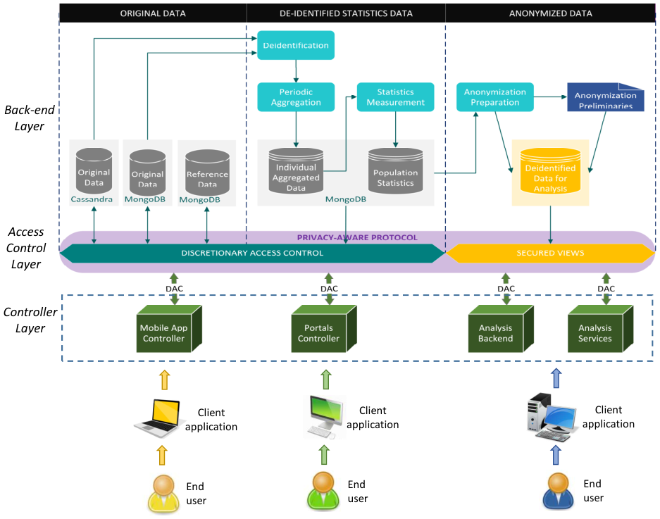
We adopted a security design architecture at every layer and between layers (see Figure 3). The layers are controller layer, access control layer and back-end layer. Each layer verifies the permissions of the lower layer. Therefore, it is more strict to check the data access from the bottom layer to top layer. Within each layer one needs to deal with the security of the following types of data original data, de-identified statistics data, and anonymised data. The security level increases from original to anonymised data, as the data gets de-identified, anonymised and perturbed respectively.
Consider the controller layer, a controller contains a set of services providing the end-users access from the external network or from another component from the system. The Mobile App Controller provides a set of interfaces for mobile users to access services such as inputting user’s information about meals, activities, etc. These mobile data values are saved in the mobile device memory before their transfer to Cassandra. The Portal controller supports a set of interfaces that can be used to access the supported web services, such as Clinical Analysis Services for measuring the activity rates, predicting the effect of users’ activities, etc. This data is transmitted to MongoDB or the related Analysis Services. Any controller access that is requested by the end-users are evaluated using RBAC as mentioned in Section III-A. The two other controllers; Web Portal and Analysis Services access the data through a Secured View.
For the access control layer, there are two investigations for evaluating its requests, that is, DAC and Secured View. These parts are executed by the authentication server. Only Mobile App Controller and Portal Controller can access DAC, while only Analysis Backend and Analysis Services can access Secured View. DAC determines weather the requesting controller is eligible to access the data in the back-end layer before performing its request. The Secured View controls and restricts access to the data by encouraging the controllers to use de-identified and anonymised data in order to protect data from possible vulnerabilities of leaking the personal information.
At the back-end layer, the database server protects data one more time against the unauthorised controllers and end-users by determining weather that controller and user can access such requested data. The Original Data is raw data and it is readable. The Identified Statistics Data contains data excluding the identity information of the users. The Anonymised Data stores data without leaving any trace of an inference to the user identity.
Furthermore, components of matrix are located in a physically distributed servers. In particular, databases are stored in different servers, i.e., original MongoDB data, original Cassandra data, and reference data of original data column are stored on the three separate servers. The individual aggregated data and population statistics data are stored on one server, and the de-identified data for analysis is stored on another server. The distributed database storage plays a key role in improving data management and privacy against the linkability attack.
Moreover, each component shown in Figure 3 is independent. Therefore, the process of receiving a request from a component and transferring the result to the next component can cause a privilege violation, if the security between components is not enforced. Hence, the data flow between components should be rigorously verified on its path at each component hop. Each component identifies the client and evaluates its permissions before processing the received request. Then it transfers the result to the next component. The next component again evaluates the client’s permissions (c.f. Figure 4) and so on until the last hop is reached. For example, in Figure 3 only mobile app and portal controllers can access directly to Role-Based Access Control (RBAC) component of the access control layer, to query the original and statistical datasets, and only Web Applications Controller and Analysis Services can access Secured Views of the access control layer. The RBAC component stores mappings of which controller/user can access which database, while the secured views store anonymised data that remove the Quasi-identifiable (QI) data [29].
V End-user Privilege Check
A request transaction can be described a security-aware matrix model. Basically, the controller layer implements a set of REST APIs to support user queries to database. An end-user who wants to access a database needs to log into a given controller. This is the first shield of the model in protecting the database. Each end-user has their own credential (i.e., user name and password ). The user can have one or more roles, denoted as , in the system (e.g., a teacher, a clinician, a school administrator, a clinic administrator, etc.), a unique ID and their organisation ID (e.g., school ID, clinic ID, etc.). To authenticate and authorise a user, the Role-Based Access Control (RBAC) technique [13] is used to handle the data access permission of controllers. The role of a user or their organisation is checked for any data access. The details are given in the following.
V-A Token-based User Authentication
User authentication happens when a user sends a log-in service request to the controller, a long with their credential as an input. The user credentials are formally formulated as follows.
Definition 1 (User Credential).
Let be a user of the system. Let be a pair of user name and password. Let , , be ’s ID, role list, and organisation ID, respectively. The user credential can be defined as:
All passwords are hashed before being stored in the database. Based on this credential, the controller authenticates the user in collaboration with a security server. To provide the user a legal authentication certification to use for their subsequent requests, the controller gets a JASON Web Token (JWT) generated by the security server. This JWT is created using the RSA algorithm with 512-bit key size. The JWT is expired after a minutes. Therefore, the user has to send a request to the server to get a new JWT. With the new JWT, the process can continue. More formally, the JWT is formulated as follows.
Lemma 1 (JWT Token).
Let , be a user and their credential. is JWT token at time for the user with credential . It is defined as follows:
| (1) |
where
- •
is a concatenation operator.
- •
contains algorithm (e.g., RSA512) and token type .
- •
is the token body involving a user ’s role list , the issuer grants this token for , an identity of , an expiration time computed since time to use the services, version of token, and the issuing time of token.
- •
is the signature of the header, payload and secret key using SHA-512.
Example 1.
An example of JWT token, generated from user ’s credential, is given in Figures 5. Figure 5a presents a code of an encoded JWT, and Figure 5b shows a structure of post-decoded JWT.
Lemma 2 (Unique User Token).
Let denote the time and the user with credential . The token is unique for user within a period of time .
Proof.
JWT token is based on the current date time of the server. The time is unique and it is obtained automatically from the server. The user name and their credential are unique. Only one hash value using SHA512 appended into the JWT token as the hashed content is unique with the unique secret key and the unique issuing time. Therefore, there is only one to be generated according to one . ∎
The Lemma 2 guarantees that a legal user can always access the controller’s services in an interval of time . As the same user credential and a requested time, the generated token is unique, hence, the controller can recognise the user identity through their token uniquely.
After successful authentication, the end-user can access the REST APIs of a given controller using their . Whenever a user requests a service, is embedded into that request. The called REST API checks if is valid, and the user’s roles in the cover the permission of using the called request.
V-B Collection-based User Authorisation
Database stores user information using a specific data structure, called collection. A collection is a list of documents and each document keeps the information of one user. This storage method does not check if all documents have a uniform format. To authorise a user, the controller needs to seek their relevant information in a collection called ”USER” of the database where all users’ information are saved. Then, it checks the user’s permission on the requested data by checking their credential and their administrative information. Specifically, a user permission is well authenticated if it satisfies two conditions, that is, (C1) only the administrative staff can access the information of users they manage (see Definition 2), and (C2) a staff member can only read or write the information of a user in their organisation (see Definition 3).
Definition 2 (Legal stewardship).
Let and be the data user and owner, respectively. Let be the role list of . Let be the organisation ID of . A Legal Stewardship is established between and iff:
where is the function returning a list of the administrative roles of ’s organisation.
Definition 3 (Solid membership).
Let , be the data user and owner, respectively. Let , be the IDs of the organisations of and , respectively. A Solid Membership between and exists iff:
Lemma 3 (User Authorisation).
Example 2.
Let consider the case where the user is a clinician of Clinic . makes a query on the user ’s information from the database. Moreover, is a patient of Clinic . Therefore, and are satisfied. Then, clinician is allowed to query on ’s information from the database.
The authorisation procedure is described in Algorithm 1, namely authorizeUserPermission(), to check the user ’s permission on some data of which aims to access. Basically, as mentioned in Definitions 2, 3, the ’s information, involving ’s role list and ’s organisation ID , are achieved from their credential (cf. Definition 1). To satisfy both lemmas above, ’s role and organisation ID need to be obtained. ’s information are queried from the relevant collections through ’s ID.
Specifically, the Algorithm 1 inputs are the list of roles of the user , their organisation ID, and ’s ID. The algorithm outputs a boolean value if the authorisation is successful, and returns a boolean value if the authorisation failed. Initially, the necessary information of are retrieved, such as their organisation ID (cf. line 1) based on which the list of administrative roles in ’s organisation are obtained (cf. line 2). Moreover, to check the two aforementioned conditions and , we initialise the two Boolean variables, i.e., and . contains the result of evaluation, and contains the result of evaluation. Initially, both are set to (cf. lines 3, 4). Then, ’s role list is examined (cf. line 5). The administrative roles in ’s organisation are investigated simultaneously (cf. line 6). Each element in is compared to each element in . If there is a case of two matched elements (cf. line 7), is set to (cf. line 8), and the two loops are stopped (cf. lines 9, 12, 13). Otherwise, the algorithm stops and return (cf. line 15). In the case of is successful, function continues to check through the two organisation IDs of and (i.e., and ) (cf. line 18). If both are different, the variable is set to (cf. line 19), function is stopped and returns (cf. line 20). In the case of the two conditions and are satisfied, the authorisation is successful, and function returns .
VI Controller Authority Evaluation
The second part of the model protecting the database is the access control layer (cf. Figure 3) which manages the data influence by controllers. In the proposed architecture, databases in the back-end layer are not accessible by all controllers. Each database is restricted for a number of specific controllers. The controller that receives user request and makes a connection to a certain database to get the data is called requesting controller. The database that contains the requested data is called requested database. There is an authentication and authorisation process between the requested database and the requesting controller whenever they handshake for a data request/response transaction. In our work, Role-Based Access Control (RBAC) technique [13] is deployed to handle the data access permission of controllers. RBAC is executed based on leveraging the controller’s identity.
VI-A Single-Sign-On Controller Authentication
To identify the requesting controller, the access control layer verifies the controller’s credential. Each controller is set with a controller name and a password by the developer. Its name must be unique in the system. Moreover, the controller has a secret key denoted as , generated from controller’s password by using some certain hash function.
Definition 4 (Controller Credential).
Let be the verified controller, controller’s name, and password, respectively. Let and be the controller’s identity and public key, respectively. Formally, the credential of a controller is defined as:
In order to monitor several users accessing system services, a Kerberos Center (KC) is used for controlling authentication (cf. Figure 6). Kerberos is an authentication protocol between unknown parties in a secure manner. involves two servers, that is, Authentication Server () and Ticket Granting Service (). In our work, this authentication protocol is operated between system controller and . The authentication is based on a ticket generated by . Basically, the ticket is generated using time constraint that limits the ticket’s time-to-live (), and the controller name is saved in the controller credential. This authentication ticket guarantees the “Single Sign On (SSO)” property of the log-in system. It indicates that the controller needs to do authentication with and then it uses this ticket for subsequent communications between the controller and the data.
Definition 5 (Service Ticket).
Let , be controller ’s ID and a time stamp of the ticket, respectively. Let , be secret key and session key of service , respectively. The service ticket of , denoted , can be generated, by an encryption algorithm:

Each ticket has a time stamp that protects it against the replay attack. Once the time stamp is reached, a new ticket is generated with a new time stamp. Therefore, the adversary cannot reuse the ticket for another transaction. Moreover, each ticket has a session key used for transactions between the service and the controller. Tickets generated for the same controller are obviously different from other controllers’ tickets. In addition, the encryption of the ticket is made with the secret key of the service, hence, it can be decrypted by only the same service.
Lemma 4 (Unique Ticket).
Let be the verified controller and ticket that TGS generates for (cf. Lemma 5). is unique.
Proof.
Given a controller and a service wants to access the data service . A ticket is generated for ; . is unique. Because, from Lemma 5, a ticket is an encryption of ’s identity , a ’s shared key , and a time stamp , where
- •
The controller identity is unique.
- •
The secret key of service , called , is unique in the system.
- •
The encryption made from the two above elements with the secret key of cannot be duplicated in the system.
Therefore, tickets of controllers are unique. ∎
Furthermore, Kerberos operates in cooperation with LDAP server. All controller’s information and their permissions are stored in the active directory of the LDAP server. For each entry in the active directory, it contains username, password, organisation, group, domain name (i.e., a link attached to the organisation), access permissions, etc.88 8 Access control list syntax; https://www-01.ibm.com/software/network/ directory/library/publications/ dmt/ref_acls.htm
The authentication protocol is depicted in Figure 6. The details of the protocol are given in Table I. To start an authentication, a controller connects to and sends its ID () to (step 1). Then, uses to lookup in its master database (step 2.1). If is not in the database, the connection is rejected. Otherwise, continues to process the authentication request. creates a time stamp for () (step 2.2). is used for checking if the ticket is still valid, otherwise, needs to be renewed. then generates a ticket, , for that is an encryption of ’s identity (i.e., ), a time stamp, (), and a session key of () (step 2.3). is used by and in subsequent steps. The ticket is used for authenticating with before getting the permission to access database. Then, retrieves the password of , that is (step 2.4) to re-generate the secret key of () (step 2.5). creates two messages; and , to be sent back to (step 2.6). and is the encryption of the session key of (). So, . sends to (step 3). generates the secret key from its password (step 4.1). uses to decrypt and obtain (step 4.2). If fails to process the decryption, it indicates that cannot access the system as their password is invalid. If successfully decrypts the message, it creates two messages; and (step 4.3). sends and to (step 5). involves , the identity of the requested service () and the requested command is executed (reading , writing , searching and/or comparing ), whereas, is an encryption of ’s identity () and the current time stamp of (). decrypts to by its secret key (step 6.1) to get the shared key and the identity of (). decrypts with the retrieved key to get the identity of () (step 6.2). compares the two identities of obtained in steps 6.1 and 6.2. If they are equal, is authenticated to . The controller authorisation is described in Section VI-A.
| 1. | - Sends controller’s ID, , to . | |
|---|---|---|
| 2. | ||
| 2.1. | - Use to check if is listed in | |
| ’s database. | ||
| 2.2. | - Create a time stamp and a session key | |
| for the ticket. | ||
| 2.3. | - Generate . | |
| 2.4. | - Retrieve from ’s database. | |
| 2.5. | - Generate controller’s secret key | |
| . | ||
| 2.6. | - Create , | |
| . | ||
| 3. | , . | |
| 4. | ||
| 4.1. | - Generate a secret key | |
| from ’s password. | ||
| 4.2. | - Decrypt by to obtain . | |
| 4.3. | - Create | |
| and . | ||
| 5. | - Sends . | |
| 6. | ||
| 6.1. | - Decrypt in by to obtain | |
| and . | ||
| 6.2. | - Decrypt by to get . | |
| 6.3. | - Compare retrieved in step 6.1. and | |
| retrieved in step 6.2. If the result is ”equal”, | ||
| is authenticated to . |
VI-B Controller Authorisation
Two kinds of permissions were investigated: Read and Write. Write permission indicates the act of inserting a new data into the database. Write (W) permission cannot delete or change data that is already stored in the database. Read (R) permission is the ability to retrieve data from the database without making any changes to the data.
Example 3.
Mobile App controller can access the Cassandra original database in the first horizontal layer (cf. Figure 3), but it cannot access the de-identified statistics data. Whereas, analysis services can access the de-identified anonymised database, but they cannot write data into the original mongoDB database.
Definition 6 (DAC Authority).
Let be the set of controllers in the system. Let be the set of user collections in the system. Let be the set permissions in the system. The set of permissions granted for each controller is defined as a 2-dimension array .
where
Example 4.
According to Figure 2, we have , , . A DAC authority is .
We use LDAP protocol for communication between the authorisation process and the active directory (AD) which stores an access control list (ACL) of permissions for each controller. The DAC table (c.f. Definition 6) is stored in the AD. Each controller’s permissions are defined in an ACL entry. Whereas, the Kerberos protocol authorises requests from the controller. The LDAP active directory can be stored in a separated LDAP server or in the same Kerberos server. The authorisation process is executed after the controller authentication was successful.
The authorisation protocol must follow the authentication process (see VI-A). The authorisation protocol is described in steps 4, 5, 6 of Figure 6 and presented in Table II. Once compares the two identities of the controller , searches in its AD for an entry that defines access permissions for to the database service . Then compares the access permissions in and the request . If they are not equal, sends a reject message to . Otherwise, issues two new messages: and (steps 1.1, 1.2) where is the issued ticket used by with the service . is an encryption made by the secrete key of service (i.e., ), of controller ID (i.e. ), time stamp (i.e. ), and the shared key of the service (i.e., ); whereas, is an encryption of the shared key of the service (i.e., ) made by ’s shared key . Then, sends and to the controller (step 2). The controller decrypts with ’s shared key to obtain the shared key of service (i.e., ), the time stamp of controller and service (i.e., ), and the identity of controller (i.e, ) (step 3.1). Then, creates a new message , that is an encryption of the controller’s identity (i.e., ) and the time stamp of controller and service (i.e., ) (step 3.2). After that, controller sends and to the database service (step 4). When receives the two messages from , it first decrypts using the secrete key of (i.e., ) to obtain the shared key of and the controller’s identity (step 5.1). decrypts using the shared key to obtain the controller’s identity (i.e., ) (step 5.2). Then, compares the two messages and (step 5.3), if the comparison results in ”equal” (i.e., ), is authorised and can access the data service . Simultaneously, creates a message that is an encryption of the time stamp granted to be used between and . After that, sends to (step 6). After receiving , decrypts using service’s shared key (i.e., ) to obtain (step 7.1). compares the two time stamp in the two messages retrieved from decrypting (step 3.1) and (step 7.1). Finally, sequentially sends its requests to .
| 1. | TGS | |
| 1.1. | Search in AD for ’s entry . | |
| 1.2. | Compare access permissions in and | |
| in . | ||
| 1.3. | If equal, do step 1.3. Otherwise, sends a rejection | |
| response to . | ||
| 1.4. | Create | |
| . | ||
| 1.5. | Create . | |
| 2. | TGS - Sends . | |
| 3. | c | |
| 3.1. | Decrypt by to obtain , | |
| , and . | ||
| 3.2. | Create . | |
| 4. | DBS - Sends . | |
| 5. | DBS | |
| 5.1. | Decrypt by to obtain | |
| and . | ||
| 5.2. | Decrypt by to obtain . | |
| 5.3. | Compare and . If , has | |
| authorised, and creates | ||
| . | ||
| 6. | DBS - Sends . | |
| 7. | c | |
| 7.1. | Decrypt by to obtain . | |
| 7.2. | Compare from steps 3.1 and 7.1. | |
| If , is authorised. |
VII Secure Data Transmission
When a subject, such as a user or a controller, attempts to access data at the back-end, it has to go through two substantial security shields, that is, authentication process (cf. Section V) and authorisation process (cf. Section VI). Even though such a data access is rigorous, the risk of data leakage is still likely to occur, especially when storing and transmitting the data. Moreover, in our system, the data storage is distributed. the databases are located on different servers (cf. Section IV). Any request to access the data the database servers collaborate to output a response.
To protect data storage against attacks, the storage system uses encryption algorithms. MongoDB supports various encryption schemas99 9 Securing MongoDB Part 3: Database Auditing and Encryption https://www.mongodb.com/blog/post/securing-mongodb-part-3-database-auditing-and-encryption, such a default with AES-256 in CBC and GCM mode.1010 10 Announcing the Advanced Encryption Standard (AES), NIST, FIPS 197, 2001 The encryption schema can be configured to comply with FIPS 140-2.1111 11 Security Requirements for Cryptographic Modules, NIST, FIPS 142, 2001 Cassandra supports Transparent Data Encryption (TDE)1212 12 Oracle Advanced Security Transparent Data Encryption Best Practices, https://www.oracle.com/technetwork/database/security/twp-transparent-data-encryption-bes-130696.pdf for a lightweight encryption of data and log files that are stored in the master database of server that contains administrative data used for monitoring and controlling the system.
Data transmission also needs to be protected against eavesdroppers. Usually the stored data are queried and transmitted in a plain form that can be read in-flight by the third party. We adopted Secure Sockets Layer (SSL)/ Transport Layer Security (TLS) [23] for securing the data transmitted over the network. This protocol is applied between any two components of the system. For example, as in Figure 3, the two parties needing a secure data transmission between themselves included Original MongoDB Database and the module De-identification, since data from Original MongoDB Database is transferred to the module De-identification.
| 1. | Send | |
| 1.1. | - SSL session request. | |
| 1.2. | - Supported protocol version, list of cipher suits . | |
| 2. | s | |
| 2.1. | Create the request accepted. | |
| 2.2. | Check supported protocol version. | |
| 2.3. | Select cipher algorithms from . | |
| 3. | Send | |
| 3.1. | - Selected cipher algorithm list. | |
| 3.2. | - SSL certificate of the public key . | |
| 3.3. | - ’s public key . | |
| 4. | c | |
| 4.1. | - Create session key . | |
| 4.2. | - Encrypt with . | |
| 5. | Send . | |
| 6. | s Decrypt by private key to get | |
| . |
The goal of this protocol is to secure the data while it is exchanged between two nodes. A secure protocol using SSL/TLS is presented in details in Table III between c and s. It is assumed that c and s have their own pair of asymmetric keys including a public key and a private key. We assume that all transactions made between c and s are secured by the session key, . Basically, SSL/TLS connection is established based on the handshake between the two sides c and s. It is assumed that each side has its own pair of public key and private key. Whenever one side, e.g. c, has an SSL/TLS connection request, c sends to s a connection request, its supported SSL/TLS protocol version (e.g., TLS 1.2), and a list of cipher suits that it supports (step 1). Cipher suit is a set of cryptographic algorithms that c supports, such as symmetric (AES-256 CBC/GCM, etc.) or asymmetric algorithms (e.g., RSA), hash function (e.g., SHA, DES) and key exchange protocols (e.g. DHE), etc. An example of cipher suit: ”ECDHE-RSA-AES128-GCM-SHA256”. Once s accepts a connection request, it creates an acceptance notification (step 2.1). Then s checks if it also supports the c’s protocol version (step 2.2). If this is the case, s matches the cipher suits in the list received from c with its supported cryptographic algorithms, and selects the suitable ones (step 2.3). s sends to c the list of selected cryptographic algorithms (step 3.1), an SSL certificate (step 3.2), and its public key (i.e., ) (step 3.3). After receiving certificate and from s, c creates a session key, used for all communications between c and s (step 4.1). c encrypts the session key with the public key to output (step 4.2). Then, c sends the encryption to s (step 5). s uses its private key to obtain the session key (step 6). Then, the session key is used for all transactions between c and s. This protocol is applied for all transactions between any of two modules or two nodes in the system.
VIII Evaluation
In this section, we evaluate the proposed model through the immune ability against attacks, that is, replay attack, eavesdropping attack and unauthorised spy.
Replay attack
Usually the adversary tries to get packets transmitted through the network, and reuses them later in the following sessions for the purpose of impersonating the sending nodes. If the attack is successful, the adversary receives the response. In case the response may contain sensitive information, the adversary can take advantage of the information for, which affects very badly the users privacy and sensitive data leakage.
Lemma 5.
In the proposed model, the adversaries cannot reuse the released packet for the replay attack purpose.
Proof.
In our model, each packet is stamped with a validation time. Based on this time, the receiving nodes in the network check the packet’s expiration, by comparing its time stamp with the current time to see if the time interval is greater than the requested time threshold. If this is a case, the packet is dropped. The problem is that how long is enough for a packet’s time to live so that the system can prevent the replay attack in time. ∎
Eavesdropping attack
The eavesdropper tries to stalk packets found in the network for the further purposes. They may be benign or malicious. If they are just honest-but-curious adversaries, they read the sensitive information in the delivered packet only to satisfy their curiosity. However, this type of attack can leave the backdoor in the system. Then, the more malicious adversary may be, successfully do their attack will be. With malicious adversaries, they are more harassed and dangerous. They aim to get more personal information to get more benefits, and may seriously harm user’s honour, privacy and finance, or to interfere with the data to change data integrity.
Lemma 6.
in the proposed model, Eavesdroppers cannot modify the package content or get any sensitive information from the communication tunnel.
Proof.
Hence, in our proposed model, we protect user data as they are transferred through the network by adopting the SSL/TLS protocol. This protocol creates a robust tunnel to hide all transmitted data especially encrypting them right when they are released from the application and at the transport layers. Moreover, with SSL/TLS protocol, a cipher suit exploits different encryption algorithms and hash functions. So, eavesdroppers cannot get any sensitive information from the tunnel. ∎
Unauthorised spy
Our model can protect data against unauthorised spies by authenticating and authorising the users and the controllers attempting to access data at the back-end. Spies can abuse the lack of security check, such as authentication and authorisation, to steal important information. After retrieving the crucial information, they turn into the previous eavesdropping adversaries, and get either benign or malicious.
Lemma 7.
In the proposed model, the user and controller cannot access database and use the data with any purpose.
Proof.
In the proposed model, the granted permissions of a user and controller must be stored in the active directory centre to be able to access database. When a user or controller sends a data access request, the server will check for suitable permission in the active directory. If this is a case, the server passes the request to the back-end database server. ∎
IX Experimental Results
This research is a part of a larger project which focuses on monitoring the changes of obesity-related behavioural risk factors (what and how children eat, how they move, how they sleep) to the prevalence of obesity, and to define a parsimonious behavioural model and data structure that will be free of redundant individual information and will minimise the use of sensitive information. The users of our system include the clinicians, school teachers, and public health authorities.
To achieve such objectives, first we build a software system that collects, stores and analyses the data sets of children and adolescent from different locations around Europe. The children and patients join the system on voluntarily basis.
The system collects their behaviours and relevant information (e.g., daily exercises, food consumption, junk food quantity, locations, clinics, schools, groups, etc.), and stores them in the two major databases: MongoDB and Cassandra. MongoDB is the core database where the most of data is stored. Cassandra is used for collecting the time-series data from users’ smart devices which are processed then stored in the local storage of the smart devices before they are transferred to MongoDB (c.f. Section IX-A).
To provide clinicians and developers a tool to access the above two databases, we implement a set of interfaces: Clinical Advisor (CA) services. A description of these services are presented in Appendix A. Each service gives an output data through a graph which the clinicians can use for comparing situations of individual children or groups of children, to monitor the children patients, to recommend the effective treatments or needed therapies suitable to each patient.
Each user in the system must be granted permissions. User permissions are discussed in Section V. Moreover, these services can be accessed by other components in the system, such as controllers or modules (c.f. Section VI).
IX-A Database Schema
In order to provide a full pack of Clinical Advisor services, we design and implement a database in term of collections in MongoDB (c.f. Figure 8), such as regions, groups, children, students, etc., and tables in Cassandra database (c.f. Figure 9), such as devices, sessions by user, physical activities by user, physical activities by date, etc.
IX-B Deployment Environment
In the proposed software system, there are two main modules, that is, Application module and Analysis module. Each module includes a front-end server and a cluster of nodes. The Application module is responsible for data storage in Cassandra and MongoDB, receives the requests, and provides services for Mobile App Controller, Web App Controller, and Portals Controller. This module hosts an Apache Balancer and a Tomcat Server. TLS/SSL and Kerberos are set up in this server. Whereas, the Analysis module provides the computations for analysis services. This module also provides the interfaces for Back-end Analysis and Services. Currently, they are all deployed on the same server. For our implementation and testing, the system uses Apache Server , Tomcat , Cassandra , MongoDB (Community version), Java, Python, JSON, Flask, Apache Maven1313 13 https://maven.apache.org/, JUnit1414 14 https://junit.org/junit5/, and SonarQube1515 15 https://www.sonarqube.org/. The Tomcat server contains the REST APIs as interfaces of the system for controllers and end-users. They contain different APIs depending on the required functionality. The Keberos and LDAP servers are always connected to the Tomcat server to get the requests from users and controllers, then process the request and reply back to the Tomcat server.


IX-C System Quality Test
We test the Clinical Advisor services after they were integrated into the main system. We run various types of tests. For code quality testing, we use the software SonarQube, and for code testing we use the tool JUnit. SonarQube measures the following criteria to ensure that the system has high quality code; no bugs, no vulnerabilities, no technical debts, no code duplication, and no duplicated blocks.
Figure 8 presents the testing results of the whole system after executing the unit testing and the code quality testing. The code smells are pieces of code that, while technically not wrong, should be altered. As all the returned measurements are rated A that means the code is of high quality.
X Conclusion
This paper, we show that designing and implementing a system for large and sensitive data-driven application is not straightforward, mainly the storage system, where the data should be stored and preserved from any unauthorised access. Moreover, this is not enough, as the data needs to be accessed for analysis purposes. This creates another challenge, as it has to be protected during its transit over the network. We can argue that these are provided by the operating system of both clients and hosts machines. However, we showed in this paper that this is not enough. Sensitive data should and must be protected independently of the underlying operating system or the system security put in place either at client or host.
The proposed architecture not only incorporates security and protection by design but also provides a framework for any system architecture that deals with data-driven applications. Our architecture separates between access permissions to original data, and its derived data for special use (statistics and analysis for instance). We also provide a set of services for the external users to access the back-end. We provide a formal model to prove the system resilience to attacks and implemented it using popular and tools.
As a future work, one needs to provide an automated security-aware system for data analysis. We will to generalise the proposed architecture to any system where the data is the main focus. We will also improve the anonymised data in the architecture (see Figure 3), to provide a set of secure interfaces for external users to do data mining on the anonymous data.
Appendix A Clinical Advisor (CA) Graphs
We implemented the graphs to support clinicians in observing and helping the patients. The Clinical Advisor module of the system provides basic statistics via two RESTful web services interface, Individual and Population.
A-A Individual Services
An indicator is measurable quantity to provide the information about an individual’s behaviour in eating, physical activity and sleep. This service provides statistical graphs of the user. Given a time period and an indicator, these graphs show how the indicator changes during that period.
A-A1 Numeric Indicators
There are three types of graphs for Individual services for supporting clinicians. The changes are displayed by average values.

- •
Daily MET. This graph shows the average MET (Metabolic equivalent of task), which expresses the energy cost in physical activities during a period of time. Higher MET corresponds to heavier activities. This graph supports clinicians in checking the effectiveness of physical activities.
- •
Daily physical activity counts. This graph shows the average activity counts during a given time period (Figure 10). Higher counts correspond to higher physical activities. This will support clinicians in observing the effectiveness of physical activities.
- •
Daily physical activity steps. This graph shows the average activity steps during a time period. This graph provides clinicians a tool of monitoring the most popular types of physical activities (walking, running, etc.).
A-A2 Categorical Indicators
Categorical indicators allow to provide graphs for meal types, visited locations, and transportation modes. Changes are expressed by the distribution of values.
- •
Daily dietary. This graph shows the distribution of meals at different times during the day. With this graph, clinicians can get information about the dietary habits of children (c.f. Figure 11).

Fig. 11: A graph of daily meals of a child in Clinical Portal - •
Daily visited locations. This graph shows the location types a child usually visits. With this graph, clinicians can learn more about favourite locations of children and their habits. For example, if children prefer sedentary activities or dynamic activities, how often children join community activities or use recreational facilities.
- •
Daily transportation. This graph presents commuting travels and frequent travelling methods. Clinicians know their travel habits.
A-B Population Services

A population can be patients of a clinic, students of a school. The population graphs provide the statistical data of a population. These graphs contain the body measurement distributions (height, weight, BMI class) that are typical indicators to consider to measure children body fat. Using these graphs, clinicians can know the prevalence of obesity in a community or population.
A-C Mock-up Services
As a future works, we will implement more graphs to support clinicians. The planned graphs are listed below:
- •
Graphs for food consumption and body measurements shows the relationship between food consumption and body measurements (e.g., weight, BMI) over a time period.
- •
Graphs for physical activities and body measurements shows the relationship between physical activities and body measurements (e.g., weight, BMI) over a time period.
- •
Graphs for food environment and body measurements shows the relationship between food environment and body measurements (e.g., weight, BMI) over a time period.
Acknowledgment
The work leading to these results has received funding from the European Community’s Health, demographic change and well-being Programme under Grant Agreement No. 727688, 01/12/2016 - 30/11/2020
References
- [1] M. A. Ahmad. Secfhir: A security specification model for fast healthcare interoperability resources. International Journal of Advanced Computer Science and Applications (IJACSA), 7(6), 2016.
- [2] Aadil Al-Mahrouqi, Sameh Abdalla, and Tahar Kechadi. Cyberspace forensics readiness and security awareness model. International Journal of Advanced Computer Science and Applications, 6(6), 2015.
- [3] B. Blobel, D. M. Lopez, and C. Gonzalez. Patient privacy and security concerns on big data for personalized medicine. Springer Journal in Health and Technology, 6(1):75–81, 2016.
- [4] A. Boonyarattaphan, B. Yan, and C. Sam. A security framework for e-health service authentication and e-health data transmission. In 9th International Symposium on Communications and Information Technology, pages 1213–1218, Incheon, Korea, September 2009.
- [5] B. Carminati, E. Ferrari, and N. H. Tran. Enforcing trust preferences in mobile person-to-person payments. In 2013 International Conference on Social Computing, pages 429–434, Sep. 2013.
- [6] B. Carminati, E. Ferrari, and N. H. Tran. Secure web service composition with untrusted broker. In 2014 IEEE International Conference on Web Services, pages 137–144, June 2014.
- [7] B. Carminati, E. Ferrari, and N. H. Tran. A privacy-preserving framework for constrained choreographed service composition. In 2015 IEEE International Conference on Web Services, pages 297–304, 2015.
- [8] S. Cohen and K. Mitchell. White paper: Wellness plans – diagnosing compliance concerns. FYI - In Depth, Xerox, 38, December 2015.
- [9] A. Dubovitskaya, Z. Xu, S. Ryu, M. Schumacher, and F. Wang. Secure and trustable electronic medical records sharing using blockchain. Annual Symposium proceedings (AMIA), pages 650–659, 2018.
- [10] Ashutosh Dhar Dwivedi, Gautam Srivastava, Shalini Dhar, and Rajani Singh. A decentralized privacy-preserving healthcare blockchain for iot. Sensors, 19(2), 2019.
- [11] Tariq N. Ellahi, Benoit Hudzia, Liam McDermott, and M. Tahar Kechadi. Security framework for P2P based grid systems. In 5th International Symposium on Parallel and Distributed Computing (ISPDC), pages 230–237, Timisoara, Romania, July 2006.
- [12] Saad Fehis, Omar Nouali, and M-Tahar Kechadi. A New Distributed Chinese Wall Security Policy Model, 11(4), 2016.
- [13] D. Ferraiolo and R. Kuhn. Role-based access controls. In 15th NIST-NCSC National Computer Security Conference, pages 554–563, Baltimore, MD, USA, March 2009.
- [14] L. Guo, C. Zhang, J. Sun, and Y. Fang. Paas: A privacy-preserving attribute-based authentication system for ehealth networks. In IEEE 32nd International Conference on Distributed Computing Systems, pages 224–233, Macau, China, June 2012.
- [15] H. Huang, T. Gong, N. Ye, R. Wang, and Y. Dou. Private and secured medical data transmission and analysis for wireless sensing healthcare system. IEEE (Journal) Transactions on Industrial Informatics, 13(3):1227–1237, June 2017.
- [16] J. Kohl and C. Neuman. White paper: The kerberos network authentication service (v5). https://tools.ietf.org/html/rfc4120, 2005.
- [17] D. Kotz, C. A. Gunter, S. Kumar, and J. P. Weiner. Privacy and security in mobile health: A research agenda. Journal of Computer, 49(6):22–30, 2016.
- [18] W. Liu, X. Liu, J. Liu, Q. Wu, J. Zhang, and Y. Li. Auditing and revocation enabled role-based access control over outsourced private ehrs. In IEEE 7th International Symposium on Cyberspace Safety and Security, pages 336–341, New York, USA, 2015.
- [19] M. Marci, R. Tanya, and S. Shankar. Security and privacy issues with health care information technology. In 28th IEEE EMBS Annual International Conference, pages 5453–5458, New York, USA, 2006.
- [20] A. Marcos, H. Leonardo, M. Bruno, C. Tereza C. M. B., and N. Mats. Secourhealth: A delay-tolerant security framework for mobile health data collection. IEEE Journal of Biomedical and Health Informatics, 19(2):761–772, 2015.
- [21] Yinbin Miao, Jianfeng Ma, Ximeng Liu, Fushan Wei, Zhiquan Liu, and Xu An Wang. m2-abks: Attribute-based multi-keyword search over encrypted personal health records in multi-owner setting. Journal of Medical Systems, 40(11):246, Oct 2016.
- [22] T. A. Nguyen, N. A. Le-Khac, and M. T. Kechadi. Privacy-aware data analysis middleware for data-driven ehr systems. In Future Data and Security Engineering (FDSE), pages 335–350, Ho Chi Minh City, Vietnam, 2017.
- [23] R. Oppliger. SSL and TLS: Theory and Practice. Information Security and Privacy. Artech House, 2005. ISBN 978-1596934474.
- [24] K. Ostherr, S. Borodina, R. C. Bracken, C. Lotterman, E. Storer, and B. Williams. Trust and privacy in the context of user-generated health data. Journal of Big Data and Society, 4(1), 2017.
- [25] S. Rao, S. N. Suma, and M. Sunitha. Security solutions for big data analytics in healthcare. In Second International Conference on Advances in Computing and Communication Engineering, pages 510–514, Dehradun, India, 2015.
- [26] B. R. Schatz. National surveys of population health: Big data analytics for mobile health monitors. Journal of Big Data, 3(4):219–229, 2015.
- [27] J. Sermersheim. Lightweight directory access protocol (ldap): The protocol, 2006. Copyright (C) The Internet Society (2006). https://tools.ietf.org/html/rfc4511.
- [28] J. Shafer, S. Rixner, and A. L. Cox. The hadoop distributed filesystem: Balancing portability and performance. In IEEE International Symposium on Performance Analysis of Systems and Software (ISPASS), pages 122–133, White Plains, New York, 2010.
- [29] L. Sweeney. Project technical report: Simple demographics often identify people uniquely. 2000. http://dataprivacylab.org/projects/identifiability/paper1.pdf.
- [30] W. D. Yu, C. Pratiksha, S. Swati, S. Akhil, and M. Sarath. A modeling approach to big data based recommendation engine in modern health care environment. In 39th Annual Computer Software and Applications Conference, pages 75–86, Taichung, Taiwan, 2015.
- [31] R. Zhang and L. Liu. Security models and requirements for healthcare application clouds. In IEEE 3rd International Conference on Cloud Computing, pages 268–275, Florida, USA, 2010.