Edge vectors on plabic networks in the disk and amalgamation of totally non-negative GrassmanniansThanks: This research of S. Abenda has been partially supported by MMNLP-INFN and GAST-INFN Research Projects, GNFM-INDAM, and RFO University of Bologna. The work of P.G. Grinevich has been performed at the Steklov International Mathematical Center and supported by the Ministry of Science and Higher Education of the Russian Federation (agreement no. 075-15-2022-265). Partially this research was fulfilled during the visit of the second author (P.G.) to IHES, Université Paris-Saclay, France in November 2017.
Abstract.
The amalgamation of cluster varieties introduced by Fock and Goncharov in [21] plays a relevant role both in mathematical and physical problems. In particular, amalgamation in the totally non-negative part of positroid varieties is explicitly described as gluing of several copies of small positive Grassmannians, and , has important topological implications [53] and naturally appears in the computation of amplitude scatterings in SYM theory [9, 10]. Lam [44] has proposed to represent amalgamation in positroid varieties by equivalence classes of relations on bipartite graphs and to identify total non-negativity via appropriate edge signatures. In this paper we provide an explicit geometric characterization of such signatures in the setting of the planar bicolored trivalent directed perfect networks in the disk introduced in [52] to parametrize positroid cells using systems of relations for -vectors.
More precisely, to any such graph , we associate a geometric signature satisfying both the full rank condition and the total non–negativity property on the full positroid cell. Such signature is uniquely identified by geometric indices (local winding and intersection number) ruled by the orientation and gauge ray direction on .
The principal result is the enrichement of Postnikov’s construction in [52] by associating measurements not only to boundary edges or vertices, but to internal edges as well. Indeed we generalize prior results by Postnikov [52] and Talaska [61] providing an explicit representation of the solution to the system of geometric relations on the network of graph and positive weights. At this aim, we assign canonical basis vectors in at the boundary sinks and define the vectors components at the edge as (finite or infinite) summations over the directed paths from to the given boundary sink. Such edge vectors have the following properties:
1) They solve the geometric system of relations on ;
2) Their components are rational in the weights with subtraction–free denominators, and have explicit expressions in terms of the conservative and edge flows of [61]. At the boundary sources they coincide with the entries of the boundary measurement matrix defined in [52]. If is acyclically orientable, all components are subtraction–free rational expressions in the weights with respect to a convenient basis. Null edge vectors may occur on reducible networks not acyclically orientable;
3) We provide explicit formulas both for the transformation rules of the edge vectors with respect to the orientation and the several gauges of the given network, and for their transformations due to moves and reductions of networks.
Finally, we associate a Kasteleyn orientation to the graph following [17]. If the graph is bipartite, it is known that the partition functions of dimer configurations on the graph with given boundary conditions coincide with the Plucker coordinates of the corresponding point of the totally non-negative Grassmannian [54, 44, 60, 1, 8]. In the case of plabic graphs which are not bipartite we show that the partition function for a given boundary condition is not a multiple of the corresponding minor of the boundary measurement matrix. Therefore, in this case a statistical mechanical interpretation of the boundary measurement map remains open.
2010 MSC. 14M15; 05C10, 05C22.
Keywords. Totally non-negative Grassmannians, positroid cells, planar bicolored networks in the disk, moves and reductions, amalgamation, boundary measurement map, edge vectors.
1. Introduction
Totally non–negative Grassmannians historically first appeared as a special case of the generalization to reductive Lie groups by Lusztig [46, 47] of the classical notion of total positivity [27, 28, 57, 36]. As for classical total positivity, naturally arise in relevant problems in different areas of mathematics and physics. The combinatorial objects introduced by Postnikov [52], see also [55], to characterize have been linked to the theory of cluster algebras of Fomin-Zelevinsky [24, 25] in [58, 51]. The topological characterization of is provided in [26] (see also [54, 56]).
In particular the planar bicolored (plabic) graphs introduced in [52] have appeared in many contexts, such as the topological classification of real forms for isolated singularities of plane curves [23], they are on–shell diagrams (twistor diagrams) in scattering amplitudes in supersymmetric Yang–Mills theory [9, 10, 11] and have a statistical mechanical interpretation as dimer models in the disk [43]. Totally non-negative Grassmannians naturally appear in many other areas, including the theory of Josephson junctions [14], statistical mechanical models such as the asymmetric exclusion process [18] and in the theory of integrable systems. In particular, plabic graphs have been used in KP integrable hierarchy both to describe the asymptotic behavior and the tropical limit of KP-II real regular multi–line soliton solutions (see [15, 40, 41] and references therein) and in [2, 3, 4, 5, 6] to parametrize such soliton solutions as limits of real finite–gap KP–II solutions via real regular divisors on –curves in agreement with [20, 42].
The motivation to the present research comes from problems of mathematical and theoretical physics where total positivity is connected to some measurable outcome at the boundary of the graph due to real local interactions occurring at its vertices. In the mathematical language, this issue may be described in terms of the amalgamation of cluster varieties originally introduced by Fock and Goncharov in [21], which has relevant applications in cluster algebras and relativistic quantum field theory [9, 10, 35, 50]. In particular, if the projected graphs represent positroid cells, amalgamation of adjacent boundary vertices preserves the total non–negativity property and plays a relevant role also in real algebraic geometric problems such as polyhedral subdivisions [53]. In connection to relevant open problems in theoretical physics, Lam [44] has proposed to use spaces of relations on planar bipartite graphs to represent amalgamation in totally non–negative Grassmannians and to characterize their maximal rank and total non-negativity properties in terms of admissible edge signatures on the final planar graph.
In this paper we provide an explicit solution to the above problem in the form of geometric conditions on trivalent plabic graphs so that the amalgamation of several copies of little positive Grassmannians and preserves total non–negativity and produces the expected positroid cell . We explicitly characterize such admissible edge signatures by defining convenient geometric indices on each planar bicolored directed trivalent perfect (plabic) graph in the disk; such geometric signatures are parametrized by the perfect orientations of the graph and the gauge ray directions.
In our construction, we provide an explicit characterization of the edge vectors solving such systems of relations at the internal edges using Talaska-type formulas [61]. We use –row vectors and perfectly oriented trivalent plabic networks because this representation is suitable for the mathematical formulation of several problems connected to total non–negativity [2, 4, 5, 6, 9, 10, 15, 40, 41]. We remark that the formulation of the same problem in terms of –column vectors is straightforward and amounts to exchange relations at white and black vertices. The transformation of the trivalent plabic graph into an equivalent bipartite one using Postnikov moves avoids the use of orientation at the price of increasing the valency of the internal vertices. We remark that valency greater than three may lead to the introduction of extra parameters in applications [2, 4].
On a given plabic network representing a point in , the –th edge vector component on is defined as a summation over all directed paths from to the boundary sink . The absolute value of the contribution of one such path is the product of the edge weights counted with their multiplicities, whereas its sign depends on the sum of two indices: the generalized winding index of the path with respect to a chosen gauge direction , and the number of intersections of the path with the gauge rays starting at the boundary sources. Such intersection index generalizes the notion of boundary sources passed by a directed path from boundary to boundary to the case in which the initial vertex of is internal to the graph. We remark that the idea of fixing a ray direction to measure locally the winding first appears in [30].
For any given choice of positive edge weights on the chosen oriented graph with fixed gauge ray direction, we show that the system of edge vectors solves a full rank system of relations and that the solution of such system at the boundary sources provides the boundary measurement matrix associated to such network by Postnikov [52]. The vector components at internal edges are rational in the weights with subtraction–free denominators and are explicitly computed using conservative and edge flows, thus extending the results in [61] to the interior of the graph. Moreover, if the graph is reduced in Postnikov sense, the vector components at all internal edges are subtraction–free rational expressions in the weights, therefore they satisfy the stronger condition settled for the boundary measurement map in [52]. On the contrary, null edge vectors may appear in reducible networks even if there exist paths from the given edge to the boundary sinks. In such case, we conjecture that it is possible to obtain non–zero edge vectors using the extra gauge freedom of weights on reducible networks. We also explicitly characterize how edge vectors change with respect to changes of orientation, of gauge ray direction and with respect to Postnikov moves and reductions.
In particular, the image of the boundary measurement map coincides with if the vector space is .
We remark that in [1], it is proven that the geometric signature fulfills a variant of Kasteleyn theorem in [60] in the case of reduced bipartite graphs. In such case the minors of the boundary measurement matrix are the partition functions of weighted dimer configurations up to a multiplicative constant. On the contrary, here we show that there is no such relation between the boundary measurement map and dimer partition functions when the plabic graph is not bipartite. Therefore the statistical mechanical interpretation of the boundary measurement map remains an open problem in such case.
In the continuation to this paper [7], we provide a combinatorial representation of geometric signatures: the total signature on each face depends just on the number of white vertices bounding it. We show that there is a unique geometric signature on each graph up to gauge equivalence, and that this is the unique signature inducing Postnikovs boundary measurement map. Moreover, no other signature is compatible with total non-negativity for arbitrary positive weights. In [5, 6] we apply the present construction to detect the position of real regular divisors associated to multi–line real regular KP–II solitons on the ovals of rational degenerations of non–singular –curves dual to plabic graphs.
In [8] an alternative construction of vector–relation configurations has been proposed on undirected reduced bipartite graphs representing positroid varieties in with the purpose of connecting the pentagram map [59] and –nets [12, 19].
Natural open problems are connected to the generalization of the present construction on Riemann surfaces with boundaries, the investigation of the notion of boundary measurement map in such setting and its connections to field theoretical models and integrable systems. There are several results in this direction so far and relevant applications.
In particular, in [29] it is proven that the boundary measurement map possesses a natural Poisson-Lie structure, compatible with the natural cluster algebra structure on such Grassmannians. An interesting open question is how to use such Poisson–Lie structure in association with our geometric approach.
In [31] and [48], the authors respectively extend the boundary measurement map to the case perfectly oriented planar networks in the annulus and to perfectly oriented bicolored graphs on Riemann surfaces with boundaries. Moreover in [48] explicit expressions for the bondary measurements are provided using a generalization of Talaska formula [62]. The main difference with the case of the disk is that the boundary measurement map defined in [30, 48] depends on the chosen perfect orientation on the graph in an untrival way. So a natural open question is whether it is possible to provide a natural geometric classification of all possible boundary measurement maps.
We plan to pursue such detailed construction in a different paper with the aim of generalizing the construction of KP-II divisors for other classes of soliton solutions and compare it with the so–called top-down approach for non-planar diagrams from gluing legs which plays a relevant role in the computation of scattering amplitudes of field theoretical models [9, 10, 13]. An extension of the present construction to planar graphs in geometries different from the disk would open also the possibility of investigating the generalization of geometric relations in the framework of discrete integrable systems in cluster varieties [34, 21], dimer models [39, 16, 17] and possible relations to the Deodhar decomposition of the Grassmannian [49, 63], which has already proven relevant for KP soliton theory [40].
Main results and plan of the paper
In Section 2 we recall some useful properties of totally non–negative Grassmannians and set up the class of networks used throughout the paper. In the following is a positroid cell of dimension , and is a planar bicolored directed trivalent perfect (plabic) graph in the disk representing (Definition 2.3). In our setting boundary vertices are all univalent, internal sources or sinks are not allowed, internal vertices may be either bivalent or trivalent and may be either reducible or irreducible in Postnikov sense [52]. has faces where if the graph is reduced, otherwise .
Then, we fix an orientation on and assign positive weights to the edges so that the resulting oriented network represents a point . On we also fix a reference direction (gauge ray direction, see Definition 3.1) to measure the winding and count the number of boundary sources encountered along a walk starting at an internal edge and reaching the boundary of the disk.
In Section 3, for any given edge in , we consider all directed walks from to the boundary and to each such walk we assign three numbers: weight, winding and number of intersections with gauge rays starting at boundary sources. Then the –th component of the edge vector is formally defined as the (finite or infinite) sum of such signed contributions over all directed walks from to the boundary vertex . By definition, edge vectors satisfy linear relations at the vertices and this system has full rank on (Theorem 3.11).
Therefore the formal sums may be substituted by rational expressions in the edge weights and, adapting remarkable results in [52, 61] to our setting, in Theorem 3.12 we prove that the edge vectors components are rational expressions with subtraction–free denominators and may be explicitly computed in terms of the conservative and of the edge flows defined in Section 3.1.
The edge vectors at the boundary sources are the row vectors of the Postnikov boundary measurement matrix minus the pivot term for the same choice of perfect orientation of the graph and positive edge weights. Therefore the image of the system of relations at the boundary vertices coincides with the boundary measurement map.
We also provide explicit formulas for the dependence of the edge vectors on the orientation and the weight, vertex and ray direction gauge freedoms of planar networks (Sections 4.1, 4.2 and 4.3). The technical lemmas concerning transformation rules of edge vectors with respect to changes of orientation are proven in Appendix A. Finally we explain the dependence of edge vectors on Postnikov’s moves and reductions (Section 5).
In Theorem 6.1 we prove that if possesses an acyclic orientation, then the components of the edge vectors are subtraction–free rational in the edge weights with respect to the canonical basis. This property holds for any choice of gauge ray direction and of vertex gauge. Changes of orientation act on the components just as a multiplicative factor if we express the vectors with respect to the new basis (Corollary 6.3). Therefore zero edge vectors are forbidden in such case. On the contrary, if is reducible and does not possess an acyclic orientation, null edge vectors may appear in the solution to the linear system even if there do exist paths starting at the given edge and reaching the boundary (see Example 3.15). In this case the boundary measurement map is surjective, but not injective, since there is an extra freedom in the assignment of the edge weights, which we call the unreduced graph gauge freedom (Remark 4.9). We conjecture that, using such extra gauge freedom, it is possible to choose weights on reducible graphs so that all edge vectors are not null provided that for each edge there exists a directed path to the boundary containing it (Conjecture 6.5).
In Section 7 we restrict ourselves to plabic graphs representing irreducible positroid cells and such that for each edge there exists a directed path from boundary to boundary containing it. After recalling some results from [7], we explain the connection with amalgamation. Finally we recall the definition of Kasteleyn orientation for surface graphs with boundaries in [17] and discuss the statistical mechanical interpretation of the boundary measurement map whether the graph is bipartite or not.
2. Plabic networks and totally non–negative Grassmannians
In this Section we recall some basic definitions on totally non–negative Grassmannians and define the class of graphs representing a given positroid cell which we use throughout the text. We use the following notations throughout the paper:
- (1)
and are positive integers such that ;
- (2)
For ; if , , then ;
Definition 2.1.
Totally non-negative Grassmannian [52]. Let denote the set of real matrices of maximal rank with non–negative maximal minors . Let be the group of matrices with positive determinants. We define a totally non-negative Grassmannian as
In the theory of totally non-negative Grassmannians an important role is played by the positroid stratification. Each cell in this stratification is defined as the intersection of a Gelfand-Serganova stratum [33, 32] with the totally non-negative part of the Grassmannian. More precisely:
Definition 2.2.
The combinatorial classification of all non-empty positroid cells and their rational parametrizations were obtained in [52], [61]. In our construction we use the classification of positroid cells via directed planar networks in the disk in [52]. More precisely, we use the following class of graphs introduced by Postnikov [52]:
Definition 2.3.
Planar bicolored directed trivalent perfect graphs in the disk (plabic graphs). A graph is called plabic if:
- (1)
is planar, directed and lies inside a disk. Moreover is connected in the sense it does not possess components isolated from the boundary;
- (2)
It has finitely many vertices and edges;
- (3)
It has boundary vertices on the boundary of the disk labeled clockwise. Each boundary vertex has degree 1. We call a boundary vertex a source (respectively sink) if its edge is outgoing (respectively incoming);
- (4)
The remaining vertices are called internal and are located strictly inside the disk. They are either bivalent or trivalent;
- (5)
is a perfect graph, that is each internal vertex in is incident to exactly one incoming edge or to one outgoing edge. In the first case the vertex is colored white, in the second case black. Bivalent vertices are assigned either white or black color.
A face of the graph is called internal if it does not contain boundary vertices, otherwise is called external. The external face containing the boundary vertices , in clockwise order is called infinite, all other faces are called finite.
Moreover, to simplify the overall construction we further assume that the boundary vertices , lie on a common interval in the boundary of the disk.
Remark 2.4.
- (1)
The trivalency assumption is not restrictive, since any perfect plabic graph can be transformed into a trivalent one.
- (2)
The assumption that the boundary vertices , lie on a common interval in the boundary of the disk is not restrictive. Indeed, one may equivalently represent the given graph inside the upper half-plane, and assume that the boundary vertices lie on the line, all edges are straight intervals, and the infinite face contains the infinite point.
In Figure 1 we present an example of a plabic graph satisfying Definition 2.3 and representing a 10-dimensional positroid cell in .
In the following we also consider a more restrictive class of plabic graphs.
Definition 2.5.
PBDTP graph A plabic graph is called PBDTP if it satisfies the following additional condition: for any edge of there exists a directed path from the boundary to the boundary containing it.
The class of perfect orientations of the plabic graph are those which are compatible with the coloring of the vertices. The graph is of type if it has boundary vertices and of them are boundary sources. Any choice of perfect orientation preserves the type of . To any perfect orientation of one assigns the base of the -element source set for . Following [52] the matroid of is the set of -subsets for all perfect orientations:
In [52] it is proven that is a totally non-negative matroid . The following statements are straightforward adaptations of more general statements of [52] to the case of plabic graphs:
Theorem 2.6.
A plabic graph can be transformed into a plabic graph via a finite sequence of Postnikov moves and reductions if and only if .
A graph is reduced if there is no other graph in its move reduction equivalence class which can be obtained from applying a sequence of transformations containing at least one reduction. Each positroid cell is represented by at least one reduced graph, the so called Le–graph, associated to the Le–diagram representing and it is possible to assign positive weights to such graphs in order to obtain a global parametrization of [52].
If a positroid cell is irreducible, then the plabic graphs representing it do not possess isolated boundary vertices.
We have the following elementary Lemma.
Lemma 2.7.
- (1)
A PBDTP graph always represents an irreducible cell;
- (2)
In a PBDTP graph all internal faces contain vertices of both colors;
- (3)
If a plabic graph is PBDTP in one orientation, it is PBDTP in all other perfect orientations.
Proposition 2.8.
[52] If is a reduced plabic graph, then the dimension of is equal to the number of faces of minus 1.
The plabic graph in Figure 1 is a reduced plabic graph representing a 10-dimensional positroid cell in .
Lemma 2.9.
Relations between vertices, edges, faces Let and respectively be the number of trivalent white, trivalent black, bivalent white and bivalent black internal vertices of . Let be the number of internal edges (i.e. edges not connected to a boundary vertex) of . By Euler formula we have . Moreover, the following identities hold , . Therefore
| (2.1) |
3. Systems of edge vectors on plabic networks
For any given , there exists a network representing with plabic graph for some choice of positive edge weights [52].
In [52], for any given oriented planar network in the disk it is defined the formal boundary measurement map
where the sum is over all directed walks from the source to the sink , is the product of the edge weights of and is its topological winding index. These formal power series sum up to subtraction–free rational expressions in the weights [52] and explicit expressions in function of flows and conservative flows in the network are obtained in [61]. Let be the base inducing the orientation of used in the computation of the boundary measurement map. Then the point is represented by the boundary measurement matrix such that:
- •
The submatrix in the column set is the identity matrix;
- •
The remaining entries , , , where is the number of elements of strictly between and .
In the following we extend this measurement to the edges of plabic networks in such a way that, if is the edge at the boundary source , then the vector , with the –th vector of the canonical basis. At this aim we introduce gauge rays both to measure the local winding between consecutive edges in the path and to count the number of boundary sources passed by a path from an internal edge to a boundary sink vertex using the number of its intersections with gauge rays starting at the boundary sources. In [30], gauge rays were introduced to compute the winding number of a path joining boundary vertices. Here we use it also to generalize the index when the path starts at an internal edge .
Definition 3.1.
The gauge ray direction . A gauge ray direction is an oriented direction with the following properties:
- (1)
The ray starting at a boundary vertex points inside the disk (upper half-plane);
- (2)
This direction is not parallel to any edge;
- (3)
All rays starting at boundary vertices do not contain internal vertices of the network.
We remark that the first property may always be satisfied since all boundary vertices lie at a common straight interval in the boundary of . We then define the local winding number between a pair of consecutive edges as follows.
Definition 3.2.
The local winding number at an ordered pair of oriented edges Let be an ordered pair of oriented edges. If they are not antiparallel, let us define
| (3.1) |
Then the winding number of the ordered pair with respect to the gauge ray direction is
| (3.2) |
We illustrate the rule in Figure 2.
In the non generic case of ordered antiparallel edges, we slightly rotate the pair to as in Figure 3 and define
| (3.3) |


The local winding defined above has the following properties:
Lemma 3.3.
- (1)
If we keep , fixed and rotate the gauge direction , changes by each time passes or ;
- (2)
If we keep , fixed and rotate , changes by each time passes or .
The proof is straightforward.
Let , , , , respectively be the set of boundary sources and boundary sinks associated to the given orientation. Then draw the rays , , starting at associated with the pivot columns of the given orientation. In Figure 1 we show an example.
Let us now consider a directed path starting at a vertex (either a boundary source or internal vertex) and ending at a boundary sink , where , , …, . At each edge the orientation of the path coincides with the orientation of this edge in the graph.
We assign three numbers to :
- (1)
The weight is simply the product of the weights of all edges in , . If we pass the same edge of weight times, the weight is counted as ;
- (2)
The generalized winding number is the sum of the local winding numbers at each ordered pair of its edges with as in Definition 3.2;
- (3)
is the number of intersections between the path and the rays , : , where is the number of intersections of gauge rays with .
The generalized winding of the path depends on the gauge ray direction since it counts how many times the tangent vector to the path is parallel and has the same orientation as ; also the number of intersections depends on .
Definition 3.4.
The edge vector . For any edge , let us consider all possible directed paths , in such that the first edge is and the end point is the boundary vertex , . Then the -th component of is defined as:
| (3.4) |
If there is no path from to , the –th component of is assigned to be zero. By definition, at the edge at the boundary sink , the edge vector is
| (3.5) |
In particular, if is a boundary source, then for any , the -th component of is equal to zero. If is an edge belonging to the connected component of an isolated boundary sink , then is proportional to the –th vector of the canonical basis, whereas is the null vector if is an edge belonging to the connected component of an isolated boundary source.
If the number of paths starting at and ending at is finite for a given edge and destination , the component in (3.4) is a polynomial in the edge weights.
If the number of paths starting at and ending at is infinite and the weights are sufficiently small, it is easy to check that the right hand side in (3.4) converges. In Section 3.3 we adapt the summation procedures of [52] and [61] to prove that the edge vector components are rational expressions with subtraction-free denominators and provide explicit expressions in Theorem 3.12.
3.1. Edge–loop erased walks, conservative and edge flows
Our next aim is to study the structure of the expressions representing the components of the edge vectors.
First, following [22, 45], we adapt the notion of loop-erased walk to our situation, since our walks start at an edge, not at a vertex.
Definition 3.5.
Edge loop-erased walks. Let be a walk (directed path) given by
where is the initial vertex of the edge . The edge loop-erased part of , denoted , is defined recursively as follows. If does not pass any edge twice (i.e. all edges are distinct), then . Otherwise, set , where is obtained from removing the first edge loop it makes; more precisely, given all pairs with and , one chooses the one with the smallest value of and removes the cycle
from .
Remark 3.6.
An edge loop-erased walk can pass twice through the first vertex , but it cannot pass twice any other vertex due to perfectness. For example, the directed path at Figure 4 is edge loop-erased but it passes twice through the starting vertex . In general, the edge loop-erased walk does not coincide with the loop-erased walk defined in [22, 45]. For instance, the directed path has edge loop-erased walk and the loop-erased walk .
The two definitions coincide if starts at a boundary source.
With this procedure, to each path starting at and ending at we associate a unique edge loop-erased walk , where the latter path is either acyclic or possesses one simple cycle passing through the initial vertex. Then we formally reshuffle the summation over infinitely many paths starting at and ending at to a summation over a finite number of equivalent classes , each one consisting of all paths sharing the same edge loop-erased walk, , . Let us remark that for any , and, moreover, has the same parity as the number of simple cycles of minus the number of simple cycles of . With this in mind, we rexpress (3.4) as follows
| (3.6) |
We remark that the winding number along each simple closed loop introduces a sign in agreement with [52]. Therefore the summation over paths may be interpreted as a discretization of path integration in some spinor theory. In typical spinor theories the change of phase during the rotation of the spinor corresponds to standard measure on the group and requires the use of complex numbers. The introduction of the gauge direction forces the use of –type measures instead of the standard measure on , and it permits to work with real numbers only.
Next we adapt the definitions of flows and conservative flows in [61] to our case.
Definition 3.7.
Edge flow at . A collection of distinct edges in a plabic graph is called edge flow starting at the edge if:
- (1)
It contains the edge ;
- (2)
For each interior vertex in except the starting vertex of the number of edges of that arrive at is equal to the number of edges of that leave from ;
- (3)
If is the starting vertex of , the number of edges of that arrive at is equal to the number of edges of that leave from minus 1;
- (4)
It contains no boundary edges at sources, except possibly itself.
We denote by the collection of edge flows at edge containing the boundary sink .
Definition 3.8.
Conservative flow [61]. A collection of distinct edges in a plabic graph is called a conservative flow if
- (1)
For each interior vertex in the number of edges of that arrive at is equal to the number of edges of that leave from ;
- (2)
does not contain edges incident to the boundary.
We denote the set of all conservative flows in by . In particular, contains the trivial flow with no edges to which we assign weight 1.
The conservative flows are collections of non-intersecting simple loops in the directed graph .
In our setting an edge flow in is either an edge loop-erased walk starting at the edge and ending at the boundary sink or the union of with a conservative flow with no common vertices with . In particular, our definition of edge flow coincides with the definition of flow in [61] if starts at a boundary source.
Next we assign weight, winding and intersection numbers to edge flows, and weight to conservative flows. We remark that in [61] there is no winding nor intersection number assigned to flows from boundary to boundary.
Definition 3.9.
- (1)
We assign one number to each : the weight is the product of the weights of all edges in . In particular, we assign weight 1 to the trivial conservative flow;
- (2)
Let be the union of the edge loop-erased walk with a conservative flow with no common edges with (this conservative flow may be the trivial one). We assign three numbers to :
- (a)
The weight is the product of the weights of all edges in .
- (b)
The winding number :
(3.7) - (c)
The intersection number :
(3.8)
- (a)
3.2. The linear system on
The edge vectors satisfy linear relations at the vertices of . In Theorem 3.11 we prove that this set of linear relations provides a unique system of edge vectors on for any chosen set of independent vectors at the boundary sinks. Therefore the components of the edge vectors in Definition 3.4 have a unique rational representation. In the next Section, we provide their explicit representation in Theorem 3.12.
Lemma 3.10.
The edge vectors on satisfy the following linear equation at each vertex:
- (1)
At each bivalent vertex with incoming edge and outgoing edge :
(3.9) - (2)
At each trivalent black vertex with incoming edges , and outgoing edge we have two relations:
(3.10) - (3)
At each trivalent white vertex with incoming edge and outgoing edges , :
(3.11)
where denotes the vector associated to the edge .
This statement follows directly from the definition of edge vector components as summations over all paths starting from this edge. Let us remark that the last two formulas can be naturally generalized for perfect graphs and vertices of valency greater then 3.
In Figure 5 we illustrate these relations at trivalent vertices assuming that the incoming edges do not intersect the gauge boundary rays. For instance, if belongs to the sector , at the white vertex , where denotes the vector associated to the edge , , whereas at the black vertex and .
Next we show that, for any given boundary condition at the boundary sink vertices, the linear system in Lemma 3.10 defined by equations (3.10), (3.11) and (3.9) at the internal vertices of possesses a unique solution.
Theorem 3.11.
Full rank of the geometric system of equations for edge vectors on . Let be a given plabic network with orientation and gauge ray direction .
Given a set of linearly independent vectors assigned to the boundary sinks , let the corresponding edge vectors be defined by: , . Then the linear system of equations (3.9)–(3.11) at all the internal vertices of has full rank and the number of equations coincides with the number of unknowns, therefore it is consistent and provides a unique system of edge vectors on .
Moreover, if we properly order variables and equations, the determinant of the matrix for this linear system is the sum of the weights of all conservative flows in :
| (3.12) |
Proof.
Let be the number of faces of and let and respectively be the number of trivalent white, of trivalent black, of bivalent white, and of bivalent black internal vertices of as in (2.1), where is the number of internal edges (i.e. edges not connected to a boundary vertex) of . The total number of equations is
whereas the total number of variables is equal to the total number of edges . Therefore the number of free boundary conditions is and equals the number of boundary sinks.
Let us consider the inhomogeneous linear system obtained from equations (3.9)–(3.11) in the unknowns given by the edge vectors not ending at the boundary sinks. Let us denote the representative matrix of such linear system in which we enumerate edges so that each -th row corresponds to the equation in (3.9), (3.10) and (3.11) in which the edge ending at the given vertex is in the l.h.s.. Then has unit diagonal by construction.
If the orientation is acyclic, then it is possible to enumerate the edges of so that their indices in the right hand sight of each equation are bigger than that of the index on the left hand side. Therefore is upper triangular with unit diagonal, and the system of linear relations at the vertices has full rank.
Suppose now that the orientation is not acyclic. The standard formula expresses the determinant of as:
| (3.13) |
where is the permutation group and sign denotes the parity of the permutation .
Any permutation can be uniquely decomposed as the product of disjoint cycles:
and On the other side, for if and only if the ending vertex of the edge is the starting vertex of the edge . Therefore if and only if each cycle with in coincides with a simple cycle in the graph, i.e. encodes a conservative flow in the network. Therefore (3.13) can be equivalently expressed as:
| (3.14) |
where denotes the permutation corresponding to the conservative flow . Therefore
since the total winding of each simple cycle is , the total intersection number for each simple cycle is , and . ∎
3.3. Explicit formula for the edge vector components
A deep result of [52], see also [61], is that each infinite summation in the square bracket of (3.6) is a subtraction-free rational expression when is the edge at a boundary source. In this Section we adapt Theorem 3.2 in [61] to our purposes. The edge vectors defined in (3.4) are linear combinations of the edge vectors at the boundary sinks, and the coefficients are rational expressions in the weights with subtraction-free denominator. We express them explicitly as functions of the edge flows and conservative flows. We remark that, contrary to the case in which the initial edge starts at a boundary source, if is an internal edge, the –th component of may be null even if there exist paths starting at and ending at (see Section 6 and Figure 18).
Theorem 3.12.
Rational representation for the components of vectors Let be a plabic network representing a point with orientation associated to the base in the matroid and gauge ray direction . Let us assign the vectors to the boundary sinks , . Then edge vector at the edge defined in (3.6), is a rational expression in the weights on the network with subtraction-free denominator:
| (3.15) |
Proof.
The proof is a straightforward adaptation of the proof in [61] for the computation of the Plücker coordinates. If the graph is acyclic, the proof of (3.15) is elementary since the denominator is one and the edge flows are in one-to-one correspondence with directed paths connecting to . Therefore (3.15) and (3.4) coincide when is the -th vector of the canonical basis, .
Otherwise, in view of (3.6), we have to prove the following identity:
| (3.16) |
where in the left-hand side the first sum is over all directed paths from to . In the left-hand side we have two types of terms:
- (1)
- (2)
is not edge loop-erased or it is loop-erased, but has a common edge with .
Following [61], we prove that the summation over the second group gives zero by introducing a sign-reversing involution on the set of pairs . We first assign two numbers to each pair as follows:
- (1)
Let . If is edge loop-erased, set ; otherwise, let be the first loop erased according to Definition 3.5 and set ;
- (2)
If does not intersect , set . Otherwise, set the smallest such that and . Denote the component of containing by with .
A pair belongs to the second group if and only if at least one of the numbers , is finite. Moreover, in this case, , because if , then by the labeling rules. We then define as follows:
- (1)
If , then completes its first cycle before intersecting any cycle in . In this case , and we remove from and add it to . Then and ;
- (2)
If , then intersects before completing its first cycle. Then we remove from and add it to : , .
From the construction of it follows immediately that belongs to the second group, , and is sign-reversing since , and . ∎
Corollary 3.13.
The connection between the edge vectors at the boundary sources and Talaska formula for the boundary measurement matrix. Under the hypotheses of Theorem 3.12, let be the edge starting at the boundary source . Then the number has the same parity for all edge flows from to and it is equal to the number of boundary sources between and in the orientation ,
| (3.17) |
Therefore, for such edges and the choice , where , are the canonical basic vectors in , (3.15) simplifies to
| (3.18) |
where is the entry of the reduced row echelon matrix with respect to the base .
In particular, the edge vectors at the boundary sources are the rows of Postnikov boundary measurement matrix for the same orientation and choice of weights, except for the pivot terms which are indexed by the boundary sources themselves. Therefore the image of this map when we vary the positive weights is the full positroid cell represented by the given graph.
Proof.
First of all, in this case, each edge flow from to is either an acyclic edge loop–erased walk or the union of with a conservative flow with no common edges with . Therefore to prove that the number has the same parity for all is equivalent to prove that has the same parity for all edge loop–erased walks from to (again notations are as in Definitions 3.7, 3.8 and 3.9). Any two such loop erased walks, and , share at least the initial and the final edges and are both acyclic.
If we add an edge from to (see Fig. 6), we obtain a pair of simple cycles with the same orientation and of total winding equal to modulo . Therefore
| (3.19) |
Moreover, and
Therefore, in the first case and in the second case .
Next, let us add a directed path from to very close to the boundary to the graph (see Fig 6). Then the total intersection number of the simple cycles , are both zero and we easily conclude that .
Without loss of generality, we may assume that . Since is acyclic, all pivot rays , intersect an even number of times, whereas all pivot rays , intersect an odd number of times. Finally, the ray intersects an even (odd) number of times if the gauge ray lies outside (inside) the angle . Therefore, is equal to the number of sources in the interval (3.17), and the sum in the right hand side in (3.18) coincides with the formula in [61]. ∎
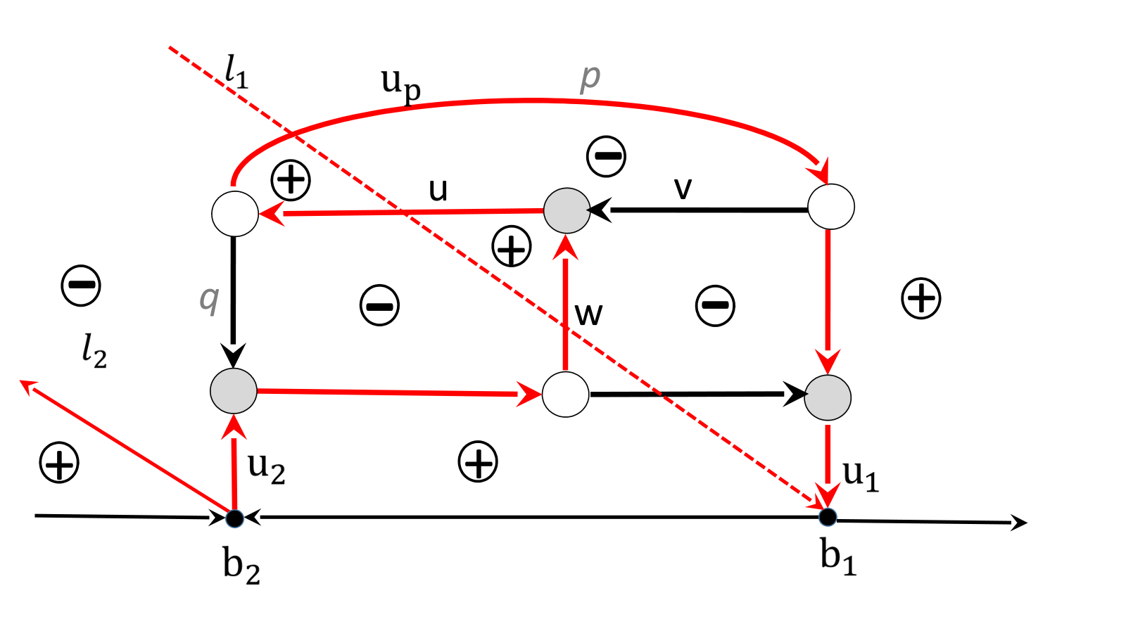
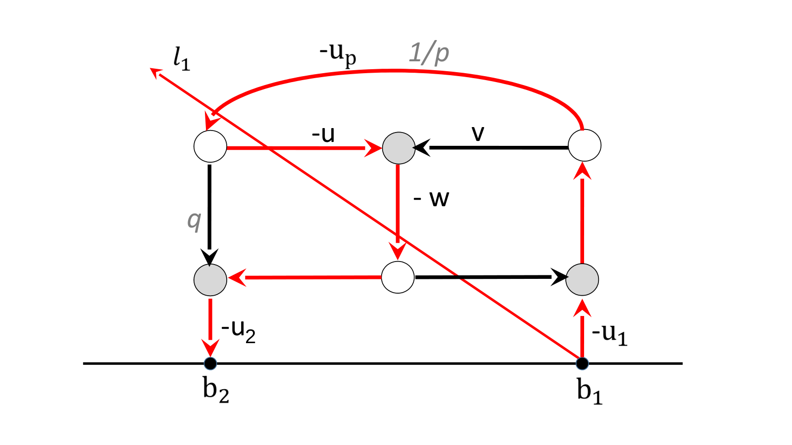
Example 3.14.
Example 3.15.
We illustrate both the Theorem and the Corollary on the example in Figure 7 [left]. The network represents the point : all weights are equal to 1 except for the two edges carrying the positive weights and . In the given orientation, the networks possesses two conservative flows of weight and . Therefore . There are two possible loop erased edge walks starting at , which coincide with the edge flows from , so that . Therefore on the edges , using (3.15) we get
We remark that , when , that is null edge vectors are possible even if there exist paths starting at the edge and ending at some boundary sink. We shall return on the problem of null edge vectors in Section 6. It is easy to check that all other edge vectors associated to such network have non–zero first component for any choice of . In particular the edge vector at the boundary source is equal to , since there are two loop erased walks starting from and three edge flows so that . The edge vector since there are two loop erased walks and three edge flows starting at . Similarly since there is only one loop erased walk and three edge flows from . Finally the representative matrix associated to this system of vectors is .
4. Dependence of edge vectors on orientation and network gauge freedoms
In this section we discuss the dependence of edge vectors on the various gauge freedoms of the network.
4.1. Dependence of edge vectors on gauge ray direction
We show that the effect of a change of direction in the gauge ray on the vectors is the following: the new vectors coincide with the old ones up to a sign, and the boundary measurement matrix is preserved.

Proposition 4.1.
The dependence of the system of vectors on the ray direction Let be an oriented network and consider two gauge directions and .
- (1)
For any boundary source edge the vector does not depend on the gauge direction and it coincides with the -th row of the generalized RREF of , associated to the pivot set , minus the –th vector of the canonical basis, which we denote ,
(4.1) - (2)
For any other edge we have
(4.2) where and respectively are the edge vectors for for the gauge direction and , par(e) is 1 if belongs to the angle , and 0 otherwise, whereas denotes the number of gauge rays passing the initial vertex of during the rotation from to inside the disk.
Proof.
Formula (4.1) follows from Corollary 3.13: indeed (3.17) implies that the components of are invariant with respect to changes of the gauge direction. Finally, since there is no path to the boundary source , the corresponding component of the edge vector is zero.
To prove the second statement, we show that, for a given initial edge , the sign contribution of each edge loop–erased walk starting at is either the same before and after the gauge ray rotation or changes in the same way for every walk independently of the destination .
Indeed let us consider a monotone continuous change of the gauge direction from initial to final . If for some the vector forms a zero angle with an edge of distinct from the initial one, the parity of the winding number of remains unchanged. On the contrary, if forms a zero angle with the initial edge , the winding number of changes its parity, and, in such case we settle . We remark that can never form a zero angle with the edge at the boundary sink in .
Similarly, if one of the gauge lines passes through a vertex in distinct from the initial vertex, then the parity of the intersection number of remains unchanged. It changes only if one of the gauge rays passes through the initial vertex of (again it can never pass through the final vertex).
Since the first edge and its initial vertex are common to all paths starting at , all components of the vector either remain invariant, or are simultaneously multiplied by . ∎
4.2. Dependence of edge vectors on orientation of the graph
We now explain how the system of vectors changes when we change the orientation of the graph. Following [52], a change of orientation can be represented as a finite composition of elementary changes of orientation, each one consisting in a change of orientation either along a simple cycle or along a non-self-intersecting oriented path from a boundary source to a boundary sink . Here we use the standard rule that we do not change the edge weight if the edge does not change orientation, otherwise we replace the original weight by its reciprocal.
Theorem 4.3.
The dependence of the system of vectors on the orientation of the network. Let be a plabic network representing a given point and be a gauge ray direction. Let , be two perfect orientations of for the bases . Let , , denote the -th row of a chosen representative matrix of . Let be the system of vectors associated to and satisfying the boundary conditions at , , whereas are those associated to and satisfying the boundary conditions at , . Then for any , there exist real constants , , such that
| (4.3) |
where for elementary transformations are as in (4.7), (4.9).
Proof.
It is sufficient to prove this statement in the case of elementary changes of orientation (see Lemmas 4.4 and 4.7 below). Indeed, a generic change of orientation is represented by the composition of a finite set of such elementary transformations, and the resulting system of vectors does not depend on the sequence of transformations. ∎
Both in the case of an elementary change of orientation along a non-self-intersecting directed path from a boundary source to a boundary sink or along a simple cycle , we provide the explicit relation between the edge vectors in the two orientations.
Given an elementary change of orientation, we assign an index to each edge of the network in its initial orientation.
First, we mark all regions of the disk by either or using the following rule.
- (1)
If is a non-self-intersecting oriented path from a boundary source to a boundary sink in the initial orientation of , we divide the interior of the disk into a finite number of regions bounded by the gauge ray oriented upwards, the gauge ray oriented downwards, the path oriented as in and the boundary of the disk divided into two arcs, each oriented from to . Then we mark a region with a if its boundary is oriented, otherwise mark it with (see Figure 9).
- (2)
If is a closed oriented simple path, it divides the interior of the disk into two regions: we mark the region external to with a and the internal region with .
Let us remark that this marking remains invariant after the change of orientation.
If the edge (respectively ), then we assign it an index as follows
| (4.4) |
where, in case the initial vertex of belongs to or , we make an infinitesimal shift of the starting vertex in the direction of before assigning the edge to a region.
If the edge (respectively ), we assign it the index
| (4.5) |
using the initial orientation as follows:
- (1)
We look at the region to the left and near the ending point of , and assign index
- (2)
It is easy to check that does not change after the change of orientation.
If the change of orientation is ruled by , we use a two-steps proof:
- (1)
We conveniently change the boundary conditions at the boundary sinks in the initial orientation of the network , we compute the system of vectors satisfying these new boundary conditions and we give explicit relations between the two systems of vectors and on ;
- (2)
Then, we show that the system of vectors in (4.7), defined on coincides with the system up to non-zero multiplicative factors.
Lemma 4.4.
The effect of a change of orientation along a non self–intersecting path from a boundary source to a boundary sink. Let and respectively be the pivot and non–pivot indices in the representative RREF matrix associated to . Assume that all the edges at the boundary vertices have unit weight and that no gauge ray intersects such edges in the initial orientation. Assume that we change the orientation along a non-self-intersecting oriented path from a boundary source to a boundary sink . Let and be the systems of vectors on corresponding to the following choices of boundary conditions at edges ending at the boundary sinks , :
| (4.6) |
where is the –th vector of the canonical basis, whereas is the row of the matrix associated to the source . Then the following system of vectors , ,
| (4.7) |
is the system of vectors on the network satisfying the boundary conditions
| (4.8) |
where is the number of intersections of the gauge ray with .
Remark 4.5.
To simplify the proof of Lemma 4.4, we assume without loss of generality that the edges at boundary vertices have unit weight and that no gauge ray intersects them in the initial orientation. This hypothesis may be always fulfilled modifying the initial network using the weight gauge freedom (Remark 4.8) and adding, if necessary, bivalent vertices next to the boundary vertices using move (M3). In Sections 4.3 and 5, we show that the effect of these transformations amounts to a well–defined non zero multiplicative constant for the edge vectors. Therefore, the statement in Lemma 4.4 holds in the general case with obvious minor modifications in the boundary conditions for the three systems of vectors , and .
Proof.
The system of vectors is the solution to the system of linear relations on for the following boundary conditions:
Then at all edges the difference is proportional to . In particular , since, by construction, . Therefore, each vector in (4.7) is a linear combination of the vector and .
Next we check that the system of edge vectors defined by (4.7) satisfies the boundary conditions for the transformed network (4.8). First of all, any given boundary sink edge , , ends in a region, whereas it starts in a region only if it intersects . The latter is exactly the unique case in which .
The edge belongs to the path and it does not intersect any gauge ray in both orientations of the network. has a region to the left and the pair is negatively oriented or it has a region to the left and the pair is positively oriented (see Figure 10). Therefore
Finally since .
To complete the proof we have to check that the system defined by (4.7) solves the linear system on at each internal vertex of the network. We prove it in Appendix A.
∎
Example 4.6.
We illustrate Lemma 4.4 for the Example 4.6 in Figure 7. Let us compute the vectors using the orientation in Figure 7 [left] and boundary condition . Then, we immediately get
|
|
Applying (4.7), we get and
|
|
since and . The latter vectors coincide with those computed directly using Theorem 3.12 in the new orientation (Figure 7[right]): there are two untrivial conservative flows of weight and so that
|
|
The effect of a change of orientation along a closed simple path on the system of edge vectors follows along similar lines as above.
Lemma 4.7.
The effect of a change of orientation along a simple closed cycle. Let be the pivot indices for . Let be the system of vectors on satisfying the boundary conditions at the boundary sinks . Assume that we change the orientation along a simple closed cycle and let be the newly oriented network. Then, the system of edge vectors
| (4.9) |
is the system of vectors on the network satisfying the same boundary conditions at the boundary sinks .
The proof that the system satisfy the linear relations for the transformed network is presented in Appendix A.
4.3. Dependence of edge vectors on weight and vertex gauge freedoms


Next we discuss the effect of the weight gauge and vertex gauge feeedom on the system of edge vectors: in both cases it is just local.
For any given , denotes a network representing with graph and edge weights . There is a fundamental difference in the gauge freedom of assigning weights depending on whether or not the graph is reduced [52].
Remark 4.8.
The weight gauge freedom [52]. Given a point and a planar directed graph in the disk representing , then is represented by infinitely many gauge equivalent systems of weights on the edges of . Indeed, if a positive number is assigned to each internal vertex , whereas for each boundary vertex , then the transformation on each directed edge
| (4.10) |
transforms the given directed network into an equivalent one representing .
Remark 4.9.
The unreduced graph gauge freedom. As it was pointed out in [52], for unreduced directed graphs there is no one-to-one correspondence between the orbits of the gauge weight action (4.10) and the points in the corresponding positroid cell. Since we do not consider graphs with components isolated from the boundary, this extra gauge freedom arises if we apply the creation of parallel edges and leafs (see Section 5). In Section 6 we show that in contrast with gauge transformations of the weights (4.10), the unreduced graph gauge freedom affects the system of edge vectors untrivially.
Lemma 4.10.
Dependence of edge vectors on the weight gauge Let be the edge vectors on the network .
- (1)
Let be the system of edge vectors on , where is obtained from applying the weight gauge transformation at a white trivalent vertex as in Figure 11 [left]. Then
(4.11) - (2)
Let be the system of edge vectors on , where is obtained from applying the weight gauge transformation at a black trivalent vertex as in Figure 11 [right]. Then
(4.12)
The proof is straightforward and is omitted.

Remark 4.11.
Vertex gauge freedom of the graph The boundary map is the same if we move vertices in without changing their relative positions in the graph. Such transformation acts on edges via rotations, translations and contractions/dilations of their lenghts. Any such transformation may be decomposed in a sequence of elementary transformations in which a single vertex is moved whereas all other vertices remain fixed (see also Figure 12).
This transformation effects only the three edge vectors incident at the moving vertex and the latter may only change of sign.
Lemma 4.12.
Dependence of edge vectors on the vertex gauge
- (1)
Let and respectively be the system of edge vectors on and on , where is obtained from moving one internal white vertex where notations are as in Figure 12[left]. Then , for all and
(4.13) - (2)
Let and respectively be the system of edge vectors on and on , where is obtained from moving one internal black vertex as in Figure 12[right]. Then , for all and
Proof.
The statement follows from the linear relations at vertices and the following identities at trivalent white vertices
| (4.14) |
and the corresponding identities at black vertices and the next Lemma. ∎
Lemma 4.13.
Denote the vertex we move by .
- (1)
If is an outgoing vector for , and the vertex at the end of is white trivalent with the outgoing vectors , , then
- (2)
If is an incoming vector for , and the vertex at the beginning of is black trivalent with the incoming vectors , , then
Proof.
Let us proof the first statement. When we move , the vector continuously changes the direction. By Lemma 3.3, the winding numbers ( respectively) changes if intersects or ( or respectively). We keep the topology of the graph fixed, therefore cannot intersect either or , therefore both windings may only change simultaneously.
The proof of the second statement uses the same arguments. ∎
5. Effect of moves and reductions on edge vectors
In [52] it is introduced a set of local transformations - moves and reductions - on planar bicolored networks in the disk which leave invariant the boundary measurement map. Two networks in the disk connected by a sequence of such moves and reductions represent the same point in . There are three moves, (M1) the square move (Figure 13), (M2) the unicolored edge contraction/uncontraction (Figure 14), (M3) the middle vertex insertion/removal (Figure 15), and three reductions (R1) the parallel edge reduction (Figure 16), (R2) the dipole reduction (Figure 17[left]), (R3) the leaf reduction (Figure 17[right]).
In our construction each such transformation induces a well defined change in the system of edge vectors. In the following, we restrict ourselves to plabic networks and, without loss of generality, we fix both the orientation and the gauge ray direction since their effect on the system of vectors is completely under control in view of the results of Section 4. We denote the initial oriented network and the oriented network obtained from it by applying one move (M1)–(M3) or one reduction (R1)–(R3). We assume that the orientation coincides with at all edges except at those involved in the move or reduction where we use Postnikov rules to assign the orientation. We denote with the same symbol and a tilde any quantity referring to the transformed network.
(M1) The square move If a network has a square formed by four trivalent vertices whose colors alternate as one goes around the square, then one can switch the colors of these four vertices and transform the weights of adjacent faces as shown in Figure 13. The relation between the face weights before and after the square move is [52] , , , , , so that the relation between the edge weights with the orientation in Figure 13 is , , , .
The system of equations on the edges outside the square is the same before and after the move and also the boundary conditions remain unchanged. The uniqueness of the solution implies that all vectors outside the square including , , , remain the same. In the following Lemma, respectively are the edges carrying the vectors in the initial configuration. For instance, is the number of intersections of gauge rays with the edge carrying the vector in the initial configuration, whereas is the winding number of the pair of edges carrying the vectors after the move because the edge has changed of versus.
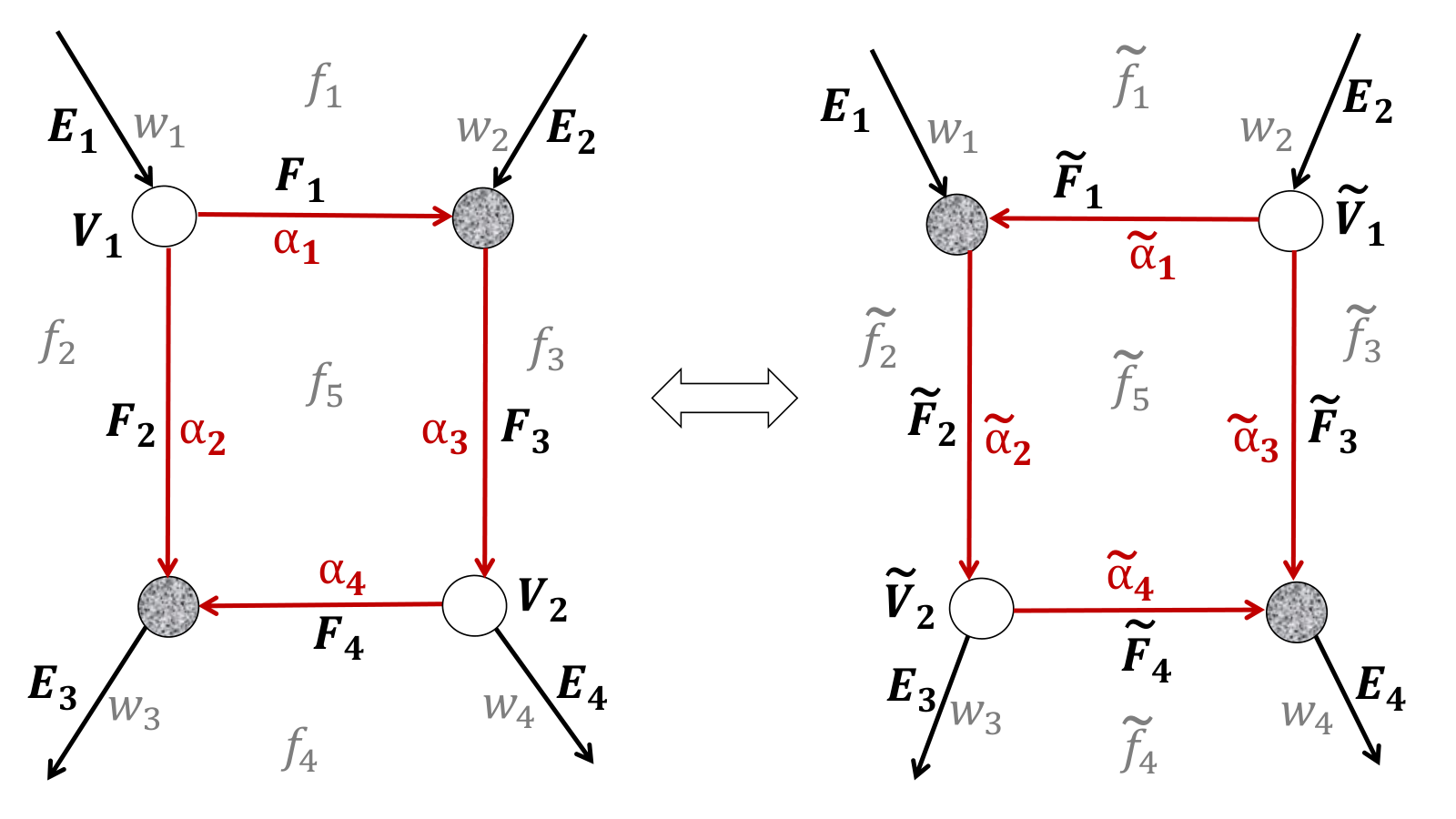
In the next Lemma we provide the transformation rules between the vectors , and , , assuming the orientation as in Figure 13.
Lemma 5.1.
The vectors after the square move are given by:
Proof.
Using the linear relations
| (5.1) |
| (5.2) |
we immediately get
Since the triple is oriented counterclockwise, the cyclic order (see Definition A.1), and the statement follows from (A.17).
Analogously,
Again, the triple is oriented counterclockwise, the cyclic order and the statement follows from (A.17). ∎

(M2) The unicolored edge contraction/uncontraction The unicolored edge contraction/uncontraction consists in the elimination/addition of an internal vertex of equal color and of a unit edge, and it leaves invariant the face weights and the boundary measurement map [52].
The contraction/uncontraction of an unicolored internal edge combined with the trivalency condition is equivalent to a flip of the unicolored vertices involved in the move (see Figure 14). We consider only pure flip moves, i.e. all vertices keep the same positions before and after the move. Moreover, we assume that the edge connecting this pair of vertices has unit weight and sufficiently small length so that no gauge ray crosses it, all other edges preserve their intersection numbers, and the winding at the vertices not involved in the move remain invariant. Therefore, additivity of the winding numbers holds in this special case with – any incoming vector, – any outgoing vector involved in the move.
Finally,
in all cases,
We remark that the flip move may create/eliminate null edge vectors. For instance suppose that and . Then in the initial configuration all edge vectors are different from zero whereas in the final .
(M3) The middle edge insertion/removal
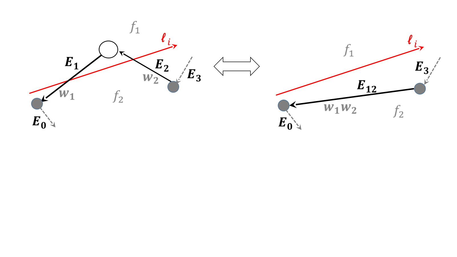

The middle edge insertion/removal consists in the addition/elimination of bivalent vertices (see Figure 15) without changing the face configuration. i.e. the triangle formed by the edges , , does not contain other edges of the network. Then the action of such move is trivial, since , so that the relation between the vectors and is simply,
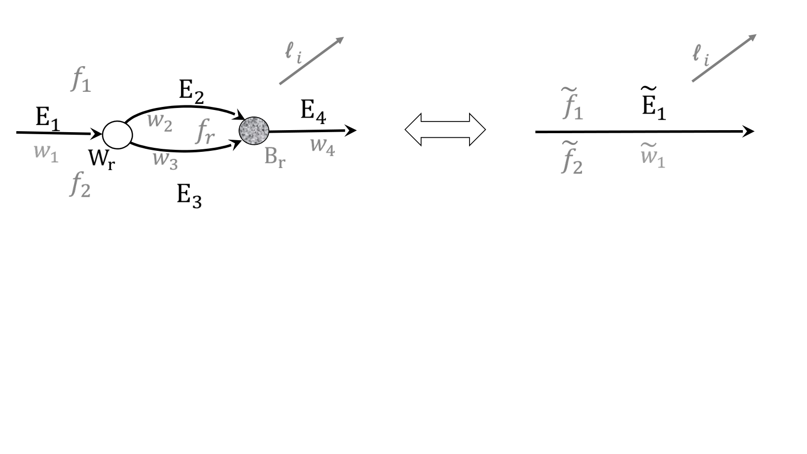
(R1) The parallel edge reduction The parallel edge reduction consists of the removal of two trivalent vertices of different color connected by a pair of parallel edges (see Figure 16[top]). If the parallel edge separates two distinct faces, the relation of the face weights before and after the reduction is , , otherwise [52]. In both cases, for the choice of orientation in Figure 16, the relations between the edge weights and the edge vectors respectively are , , , , since , and .
(R2) The dipole reduction The dipole reduction eliminates an isolated component consisting of two vertices joined by an edge (see Figure 17[left]). The transformation leaves invariant the weight of the face containing such component. Since the edge vector at is , this transformation acts trivially on the vector system.


(R3) The leaf reduction The leaf reduction occurs when a network contains a vertex incident to a single edge ending at a trivalent vertex (see Figure 17[right]): in this case it is possible to remove and , disconnect and , assign the color of at all newly created vertices of the edges and . In the leaf reduction (R3) the only non-trivial case corresponds to the situation where the faces , are distinct in the initial configuration. We assume that is short enough, and it does not intersect the gauge rays. If we have two faces of weights and in the initial configuration, then we merge them into a single face of weight ; otherwise and the effect of the transformation is to create new isolated components. We also assume that the newly created vertices are close enough to , therefore the windings are not affected. Then and , .
6. Existence of null edge vectors on reducible networks
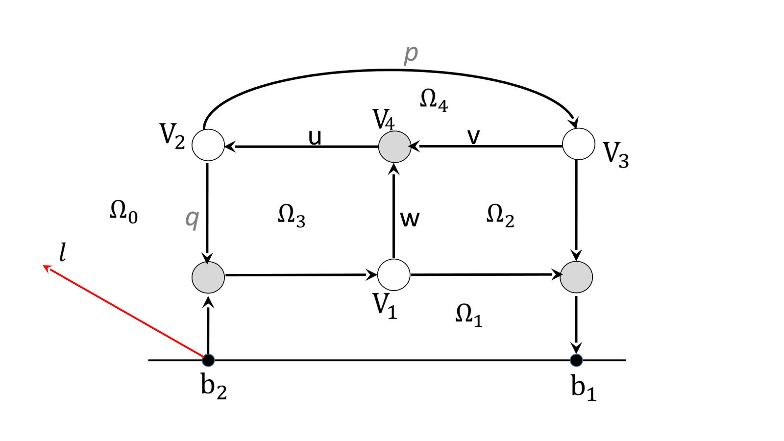
Edge vectors associated to the boundary source edges are not null due to Postnikov’s results if the boundary source is not isolated. On the contrary, a component of a vector associated to an internal edge can be equal to zero even if the corresponding boundary sink can be reached from that edge (see Example 3.15). More in general, suppose that where is an edge ending at the vertex . Then, if is black, all other edges at carry null vectors; the same occurs if is bivalent white. If is trivalent white, then the other edges at carry proportional vectors.

Of course, if the network possesses either isolated boundary sources or components isolated from the boundary, null-vectors are unavoidable. In [4], we provide a recursive construction of edge vectors for canonically oriented Le–networks and obtain as a by-product that null edge vectors are forbidden if the Le–network represents a point in an irreducible positroid cell. The latter property indeed is shared by systems of edge vectors on acyclically oriented networks as a consequence of the following Theorem:
Theorem 6.1.
Edge vectors on acyclically oriented networks Let be an acyclically oriented plabic network, which possesses neither internal sources nor sinks, representing a point in an irreducible positroid cell where . Then all edge vectors (both the internal and the boundary ones) are not-null. Moreover, in such case (3.15) in Theorem 3.12 simplifies to
| (6.1) |
where the sum runs on all directed paths starting at and ending at and is the same for all s. In particular (6.1) holds for all edges of Le-networks representing points in irreducible positroid cells.
Proof.
Let be an internal edge and let be a boundary sink such that there exists a directed path starting at and ending at . In order to prove (6.1), we need to show that has the same parity for all directed paths from to . Acyclicity and the absence of internal sources or sinks implies that there exists a directed path starting at a boundary source to . Due to acyclicity, has no common edges with except . Moreover, any other directed path from to may have a finite number of edges in common with and has no edge in common with except .
The absence of null edge vectors for a given network is independent on its orientation and on the choice of ray direction, of vertex gauge and of weight gauge, because of the transformation rules of edge vectors established in Sections 4.1, 4.2 and 4.3. We summarize all the above properties of edge vectors in the following Proposition:
Proposition 6.2.
Null edge vectors and changes of orientation, ray direction, weight and vertex gauges in . Let be a perfectly oriented plabic network with gauge direction . Let be its edge vector system with respect to the canonical basis at the boundary sink vertices. Then, on if and only if on , where is obtained from changing either its orientation or the gauge ray direction or the weight gauge or the vertex gauge.
The above statement follows from the fact that any change in the gauge freedoms - ray direction, weight gauge, vertex gauge - or in the network orientation acts by non–zero multiplicative constant on the edge vector, provided we use Lemma 4.4 to represent the edge vectors when changing of base. This property suggests the fact that each graph possesses a unique system of relations up to gauge equivalence, and in [7] we prove that this is indeed the case. In the next Corollary we explicitly discuss the special case of acyclically orientable networks.
Corollary 6.3.
Characterization of edge vectors on acyclically orientable networks Let be an acyclically orientable plabic network representing a point in an irreducible positroid cell. Then, the edge vector components are subtraction–free rational in the weights for any choice of orientation and gauge ray direction, and any given change of gauge or orientation on the network acts on the right hand side of (6.1) with a non-zero multiplicative factor which just depends on the edge.
Proof.
If is acyclically oriented, the statement follows from Theorem 6.1. The unique case which is not completely trivial is the change of orientation along a directed path from to . Then, according to the proof of Lemma 4.4, differs from by a non-zero multiplicative factor (see Equation (4.7), and is just a linear combination with the same coefficients as with respect to a different set of linearly independent vectors at the boundary sinks. ∎
In Section 5, we discussed the effect of Postnikov moves and reductions on the transformation rules of edge vectors on equivalent networks. In particular, moves (M1), (M2)-flip and (M3) preserve both the plabic class and the acyclicity of the network.
Corollary 6.4.
Absence of null vectors for plabic networks equivalent to the Le-network. Let the positroid cell be irreducible and let the plabic network represent a point in and be equivalent to the Le-network via a finite sequence of moves (M1), (M3) and flip moves (M2). Then does not possess null edge vectors.
Null-vectors may just appear in reducible not acyclically orientable networks as in the example of Figure 18. We plan to discuss thoroughly the mechanism of creation of null edge vectors in a future publication. Edges carrying null vectors are contained in connected maximal subgraphs such that every edge belonging to one such subgraph carries a null vector and all edges belonging to its complement and having a vertex in common with it carry non zero vectors. For instance in the case of Figure 18[left] there is one such subgraph and it consists of the edges and the vertices , , and . We conjecture that we may always choose the weights on reducible networks representing a given point so that all edge vectors are not null using the extra freedom in fixing the edge weights in reducible networks.
Conjecture 6.5.
Elimination of null vectors on reducible plabic networks Let be a reducible plabic network representing a given point for some irreducible positroid cell and such that it possesses a finite number of edges carrying null vectors, , , and such that through each such edge there exists a path from some boundary source to some boundary sink. Then using the gauge freedom for unreduced graphs of Remark 4.9, we may always change the weights on so that the resulting network still represents and the edge vectors , for all .
7. Amalgamation of positroid cells and Kasteleyn orientations
In this Section we provide two applications of the geometric construction of the previous Sections:
- (1)
- (2)
We discuss the statistical mechanical interpretation of the geometric signatures.
7.1. Reformulation of the geometric system of relations as a Lam system of relations for half-edge vectors
In this Section we recall some results from [7] which we apply in the following Sections.
We start reformulating the geometric relations for the edge vectors in the form proposed by Lam [44]. In [7] we have proven that any two geometric signatures on the same graph are connected by a gauge transformation. Moreover, if the plabic graph is a PBDTP graph, that is for any edge of there exists a directed path from the boundary to the boundary containing it, then the equivalence class of the geometric signature is the only one which guarantees that Lam system of relations has full rank for any choice of positive weights; moreover, in such case the image is exactly by Corollary 3.13. Finally, in [7] it is shown that the total signature of each face just depends on the number of white vertices bounding it.
In Lam [44] it is proposed to parametrize the boundary measurement map using spaces of relations on plabic graphs introducing formal half–edge variables which satisfy the following system on the graph:
Definition 7.1.
Lam system of relations
- (1)
is the weight of the oriented edge . Therefore, if one reverses the orientation, ;
- (2)
To any edge it is assigned a signature , ;
- (3)
For any edge , ;
- (4)
If , , are the edges at an -valent white vertex , then ;
- (5)
If , , are the edges at an -valent black vertex , then for all .
In [44] it is conjectured that there exist simple rules to assign signatures for the edge weights so that the above system has full rank for any choice of positive weights, and the image of this weighted space of relations is the positroid cell corresponding to the graph.
Remark 7.2.
If all internal vertices are trivalent, then the linear system can be interpreted as the amalgamation of little positive Grassmannians , [44].
Definition 7.3.
Equivalence between edge signatures. Let and be two signatures on all the edges of the plabic graph , included the edges at the boundary. We say that the two signatures are equivalent if there exists an index at each internal vertex such that
| (7.1) |
It is clear that
Proposition 7.4.
If the system of Lam relations has full rank for a given collection of weights and signature , then it has full rank for any other signature equivalent to and the same collection of weights.
Definition 7.5.
Geometric signature. Let be a plabic graph representing a –dimensional positroid cell with perfect orientation associated to the base and gauge ray direction . We call geometric signature on any signature equivalent to the following one (the right-hand sides of all equations are taken ):
- (1)
If is the edge at the boundary sink , , then
(7.2) - (2)
If is the edge at the boundary source , , then
(7.3) - (3)
If is an internal edge, then
(7.4)
Theorem 7.6.
[7] Let the network of graph be fixed. Let the geometric signature be as in Definition 7.5 and the half-edge vectors be defined as follows:
- (1)
If is a black vertex of valency , and denotes the unique outgoing edge at , then we define:
(7.5) - (2)
If is a white vertex of valency , and denotes the unique incoming edge at , then we define:
(7.6)
Then the linear system of edge vectors defined in Lemma 3.10 is equivalent to Lam system of relations in Definition 7.1. Therefore the latter has full rank for any choice of positive weights and induces Postnikov boundary measurement map in the sense of Corollary 3.13.
Remark 7.7.
When passing from the system of edge vectors (3.9)–(3.11) to the system of relations for half–edge vectors, there is a gauge freedom at each vertex which is evident from Figure 19[top]. Indeed, at any internal black vertex we may use
| (7.7) |
instead of (7.5).
These alternative choices of the correspondence between half-edge vectors and edge vectors are equivalent up to vertex gauge transformation, therefore they correspond to gauge-equivalent geometric signatures.
Remark 7.8.
We remark that with our definition of geometric signature the half-edge vectors at the boundary sources take opposite values to the corresponding edge vectors at the boundary sources. The reason of this choice is that the total geometric signature at each face is invariant with respect to changes of orientations of the graph.
We remark that the above system is meaningful also in a perfectly oriented bicolored network of valency bigger than three and may be extended to the non planar case using the cut parameter introduced in [31].
By definition, geometric signatures depend on the graph orientation, on the position of vertices in the disc and on the gauge ray direction. In [7] it is proven that all these transformations generate gauge transformations of the signature, therefore geometric signatures are well-defined. Therefore for a given graph all geometric signatures belong to the same equivalence class.
Theorem 7.9.
The total signature of a face [7] Let be a PBDTP graph in the disc representing a positroid cell , and let be its geometric signature. Then
| (7.9) |
where denotes the number of white vertices bounding the face .
Theorem 7.10.
Completeness of the geometric signatures [7]
Let be PBDTP graph, with the perfect orientation representing the irreducible positroid , be a signature on , and be a collection of positive edge weights.
Assume that Lam system of relations in Definition 7.1 possesses a solution in on the network for the signature where we assign the canonical basic vectors at the boundary sinks. Let us denote the matrix whose -th row , where is the -th vector of the canonical basis and is the half-edge vector at the boundary source , . Then for generic real weights the Lam system of equations has unique solution, and the matrix is well-defined.
If, moreover, for almost all positive weights the matrix is totally non-negative, then the signature is equivalent to the geometric signature, and the system of relations possesses a unique solution for every choice of positive weights, and the matrix coincides with the Postnikov boundary measurement matrix.
7.2. Interpretation of relations as totally non-negative amalgamation of the small Grassmannians


Next, following [9, 10, 44], we explain how the linear relations of half-edge vectors represent amalgamation of Grassmannians in the totally non–negative setting. The amalgamation of cluster varieties, of which Grassmannians are a special case, has been introduced in [21] and plays a relevant role in theoretical physics [35, 50], in particular for the computation of on–shell scattering processes in terms of simpler on-shell diagrams [9, 10]. In the case of Grassmannians it may be explicitly described as the composition of two elementary operations: disjoint sum and contraction of boundary vertices of plabic networks.
The first operation (disjoint sum) is trivial. If , with boundary vertices , and , with boundary vertices , are two bicolored networks representing respectively a point and , then the image is the point represented by the disjoint union of the two networks with boundary vertices , so that the representative matrix is in the block form
In particular if and , then .
The second operation (projection) is a map , for some , , defined in the following way. Given representing a point in and such that the edges incident at the boundary vertices and have unit weight, then is the bicolored network with boundary set obtained by removing the two boundary vertices , gluing together the two boundary edges incident to them and assigning unit weight to the resulting edge. If , and then , since the resulting network is planar in the disk. Up to cyclic permutation, and the maximal minors of the resulting matrix have the following representation in terms of the maximal minors of the initial matrix (see [9, 10, 44])
| (7.10) |
Any reduced plabic graph in the disk representing an irreducible positroid cell and such that its internal vertices are all trivalent may be obtained through such procedure. The linear system for half edge vectors introduced above provides an efficient way to construct the totally non-negative part of the image of the boundary measurement map of the final graph using those of its elementary components. The latter are, by assumption, the Le–graphs associated to and . Indeed the procedure to construct the boundary measurement matrix for any given planar bicolored trivalent network in the disk built out of the amalgamation of a finite number of trivalent black and white vertices is then straightforward:
- (1)
All the initial trivalent white or black vertices have edges with unit weight and are aligned along the boundary of the disk respecting an order in the amalgamation procedure so that at each step the resulting network be planar. Indeed it is not restrictive to assume that two vertices at the boundary will undergo the projection exactly at a step in which they are consecutive, since both the initial and the final network configurations are planar;
- (2)
A perfect orientation is chosen so that each pair of boundary vertices involved in a projection step consists in a boundary source and a boundary sink. Moreover, if the resulting network is reduced, it is not restrictive to assume that the global orientation is acyclic;
- (3)
A small oriented edge of weight is then added to the figure joining the boundary source and the boundary sink if the pair is projected at some step. Similarly, one adds an internal bivalent vertex and an edge of weight (respectively ) if the vertex is a boundary sink (respectively a boundary source) in the final network;
- (4)
Each pair of vertices joined by a weighted edge corresponding to a projection is moved inside the disk keeping the overall configuration planar;
- (5)
A gauge ray direction is chosen which satisfies the conditions settled in Section 3 and, up to slight changes in the position of the internal vertices using the vertex gauge fredom, we assume that gauge rays starting at the boundary sources may only intersect the weighted edges;
- (6)
The resulting linear system takes the form settled in Theorem 7.6, and the half edge vectors at the boundary sources give the boundary matrix associated to the final network except for the pivot terms.
We illustrate this procedure in Figure 20 for the construction of the cell . In Figure 20[left] we show the amalgamation procedure with two copies of both and which produces the Le–graph associated to . Even in this elementary example, the computation of the boundary measurement map of a point in requires the composition of four amalgamation steps and is not computationally efficient using the definition. On the contrary, the representation of the amalgamation procedure as a geometric linear system for half-edge vectors produces the boundary measurement matrix as a solution of a linear system, which is in Gaussian reduced form if the final network is acyclically oriented.
7.3. The relation between the geometric signature and Kasteleyn orientation
In this Section we introduce the dimer model on plabic graphs in the disc and discuss the relation between geometric signatures and Kasteleyn orientations.
Definition 7.12.
Let be an undirected graph in the disc. A dimer configuration is a subset of the edges of such that each internal vertex belongs to exactly one edge in , whereas the boundary vertices appear in at most once. The set of boundary vertices appearing in is the boundary of the configuration, and is denoted .
Definition 7.13.
If one assigns positive weights to the edges of , the weight of the configuration is the product of the weights on the edges in
Then the partition function of the dimer configuration sharing the same boundary condition is the sum of the weights of such configurations
| (7.11) |
If is a bipartite perfect graph in the disc representing a positroid cell in , then there exist dimer configurations on . Let us assume for simplicity that all boundary vertices are black; then the number of boundary vertices in is the same for any dimer configuration and is equal to , see [54]. Indeed, there is a natural bijection between dimer configurations and perfect orientations via the identification of the occupied sites with the edges oriented from black to white vertices.
The connection between Postnikov boundary measurement map and the dimer model in the disc in the case of bipartite graphs was first observed in [54]: the partition functions are the Plücker coordinates of the image of the boundary measurement map for the same network after a canonical transformation of the weights.
In [43] the connection between the dimer model and the positroid stratification of the totally non-negative Grassmannian was further investigated. In [60] it was topologically proven the existence of a Kasteleyn signature on bipartite graphs in the disc such that the maximal minors of the weighted Kasteleyn matrix are the the Plücker coordinates of the image of the boundary measurement map. Indeed, plabic graphs in the disc admit Kasteleyn orientations as follows from the generalization to surface graphs with boundaries [17] of a classical result [37, 38]. Therefore dimer configurations exist for the whole class of plabic graphs introduced in [52].
In [1] it is shown that in the case of reduced bipartite graphs in the disk the geometric signature defined in Section 7.1 is equivalent to the Kasteleyn signature, thus providing an explicit realization of the theorem in [60]. In [8] it is also observed that Kasteleyn signatures fulfill (7.9) on the faces of the graph.
Below we show that, on the contrary, if the plabic graph is not bipartite, the boundary measurement map has not such statistical mechanical interpretation.
Let us first recall the definition and properties of Kasteleyn orientations for plabic networks following [17]. In this case it is possible to construct a Kasteleyn orientation using a spanning tree of the dual graph by orienting arbitrarily all edges not crossed by the tree and then choosing the orientation of the remaining edges in such a way that the number of edges oriented anticlockwise on each face is odd.
Two Kasteleyn orientations are equivalent if one may be obtained from the other by a sequence of moves reversing the orientation of all edges adjacent to a given vertex; there exists a unique equivalence class of Kasteleyn orientations in the disc [17].
The weighted Kasteleyn matrix is defined as follows:
where the sum is over all edges connecting the vertices and , is the weight of the edge and
Then if we eliminate from the matrix the rows and columns corresponding to a given subset of boundary vertices , then the Pfaffian of such submatrix is the partition function of dimer configurations whose boundary vertices are the complement of [17].
If the graph is bipartite, then it is possible to associate a Kasteleyn signature to a Kasteleyn orientation in the following way:
Let us assume that all boundary vertices are black so that the number of edges bounding each face is always even. Then the product of the Kasteleyn signature along the edges of each finite face is equal to , where is the number of edges in the graph bounding . Since
where is the number of white vertices bounding , Theorem 7.9 implies that Kasteleyn and geometric signatures are equivalent in the case of bipartite graphs. Indeed, one may construct a Kasteleyn signature directly from the geometric signature in Definition 7.5:
Therefore the partition functions are the Plücker coordinates for bases of the corresponding point in the totally non-negative Grassmannian [60, 1, 8].
If the graph is not bipartite, the cardinality of is not constant if boundary vertices are equally colored. Therefore, we cannot expect a simple relation to the boundary measurement map, as we show in the following example.
Example 7.14.
In Figure 21 we show a Kasteleyn orientation on two equivalent graphs representing . For the non–bipartite graph on the left we have the following partition functions, associated respectively to the dimer configurations with no boundary vertices and with two boundary vertices:
| (7.12) | ||||
For the bipartite graph on the right we have the following partition functions, associated to the dimer configurations with exactly one boundary vertex.
| (7.13) | ||||
It is easy to check that the Pfaffian formulas from [17] hold in both cases using the Kasteleyn orientation of Figure 21.
Let us now calculate a boundary measurement matrix for both networks using Talaska’s formula (see [61] and Corollary 3.13. Let us start from the bipartite graph. The canonical rule of transformation between the edge weights on the undirected graph and the edge weights on the perfectly oriented graph is the following:
| (7.14) |
In Figure 22 (right) there are three cycles,
one loop-erased path from to
and one loop-erased path from to
Therefore the boundary measurement matrix is
| (7.15) |
and it is easy to check that in (7.14) are the Plücker coordinates of the point in .
If we compute the boundary measurement matrix for the graph in Figure 22 (left), we get the same point if use the same weights of the bipartite graph and define
It is evident that in (7.14) have no relation to the Plücker coordinates of . Therefore the statistical mechanical model associated to the boundary measurement map on plabic networks which are not bipartite is not the dimer model.
Appendix A Consistency of the system at internal vertices
Throughout this Appendix we use the same notations as in Section 4.2. In particular is the simple path changing orientation and directed from the boundary source to the boundary sink in the initial orientation, and is the simple cycle changing orientation.
We have to check that the system of vectors defined in (4.7) satisfy the linear relations at all internal vertices in the new orientation. We have to distinguish two cases:
- (1)
does not belong to the path (cycle respectively);
- (2)
belongs to the path (cycle respectively).
Denote and the intersection number for before and after the change of orientation respectively.
Let us prove Lemmas 4.4, 4.7 in the first case. In this case all vectors incident to preserve the orientation, but the intersections may change. It is easy to check that defined in (4.7) solve the linear system at for the transformed network iff for each pair where is an incoming edge and is an outcoming one at , one has
| (A.1) |
Indeed, if the orientation changes along a cycle , then and the starting and the ending point of belong to the same region as , therefore ; If the orientation changes along a path , is equal to the number of intersection of with , . If this number is even, the starting and the ending points of lie in regions with the same indexes, and . Otherwise, . Therefore (A.1) is fulfilled, and the proof for vertices not belonging to ( respectively) is completed.


Equations at a white before and after the change of variables are:
| (A.2) | ||||
| (A.3) |
Equations at a black before and after the change of variables are:
| (A.4) | |||||||||||
| (A.5) |
Taking into account that
| (A.6) |
where if orientation changes along , the statement of Lemmas 4.4, 4.7 is equivalent to the following identities:
| (A.7) | |||
| (A.8) | |||
| (A.9) |
Using the definition of the index in (4.4) and (4.5), the left-hand side of Equation (A.7) can be rewritten as:
| (A.10) |
From (A.1) it follows that the first parentheses equals to 0 , therefore it is sufficient to check that
| (A.11) |
Indeed, if and belong to the same half-plane with respect to , then and . If they belong to opposite half-planes, then , one of the windings , equals to and the other is zero (see Fig 24). It proves (A.11)
To complete the proof, we use the cyclic order:
Definition A.1.
Cyclic order. Generic triples of vectors in the plane have natural cyclic order. We write if the triple , , is ordered counterclockwise, and if the triple , , is ordered clockwise (see Fig 25).
Lemma A.2.
Let belong to or , be the edges at , where , belong to (), and () denotes an incoming (outgoing) edge respectively in the initial configuration (see Figure 23).
- (1)
If is black, then:
(A.14) (A.15) - (2)
If is white, then:
(A.16) (A.17)
Proof.
In the proof all identities hold mod 2.
To prove (A.14), let us remark that if and only if both the starting and the ending points of lie in regions equally marked. Moreover if and only if the starting point of lies in area with the same marking as the area at the left of the ending point of . Therefore if vector lies to the left of the directed chain , otherwise this expression equals 1. But vector lies to the left (right) of the directed chain if and only if (1 respectively).
To prove (A.16), let us remark that if and only if the starting point of lies in area at the left of the ending point of . In this case vector lies to the left (right) of the directed chain if and only if (1 respectively).
Lemma 3.3 implies that they hold true for all configurations and gauge ray directions:
- (1)
The right-hand side of (A.15), (A.17) does not depend on . The terms in the left-hand side change when passes , , , ( , , , ) if is black (white) respectively. If passes either or (), then two winding terms change by 1 contemporarily. If passes either or , exactly one winding term and change. In all cases equality remains true;
- (2)
If we keep and all vectors except fixed, both the right-hand side and the left-hand side change by 1 when () passes , , and remain fixed in all other cases, therefore the equality remains true;
- (3)
If we keep and all vectors except fixed, both the right-hand side and the left-hand side change by 1 when passes , (), and remain fixed in all other cases, therefore the equality remains true.
∎
Acknowledgments
The authors would like to express their gratitude to T. Lam for pointing our attention to Reference [8].
References
- [1] Abenda, S. “Kasteleyn theorem, geometric signatures and KP-II divisors on planar bipartite networks in the disk.”, Math. Phys. Anal. Geom. 24, Art. #35, (2021): 64 pp.
- [2] Abenda, S., and P.G. Grinevich, “Rational degenerations of -curves, totally positive Grassmannians and KP–solitons.” Commun. Math. Phys. 361, no. 3 (2018): 1029–1081.
- [3] Abenda, S., and P.G. Grinevich, “Real soliton lattices of the Kadomtsev-Petviashvili II equation and desingularization of spectral curves corresponding to .” Proc. Steklov Inst. Math. 302, no. 1 (2018): 1–15.
- [4] Abenda, S., and P.G. Grinevich, “Reducible -curves for Le-networks in the totally-nonnegative Grassmannian and KP–II multiline solitons.” Sel. Math. New Ser. 25, no. 3 (2019) 25:43.
- [5] Abenda, S., and P.G. Grinevich, KP theory, plabic networks in the disk and rational degenerations of –curves. arXiv:1801.00208.
- [6] Abenda, S., and P.G. Grinevich, Real regular KP divisors on –curves and totally non-negative Grassmannians, arXiv:2002.04865.
- [7] Abenda, S., and P.G. Grinevich, Geometric nature of relations on plabic graphs and totally non-negative Grassmannians, arXiv:2111.05782, to appear in Int. Math. Res. Not. IMRN (2022).
- [8] Affolter, N., M. Glick, P. Pylyavskyy, and S. Ramassamy, Affolter, N., M. Glick, P. Pylyavskyy, and S. Ramassamy, “Vector–relation configurations and plabic graphs”, Sém. Lothar. Combin. 84B (2020), Art. #91, 12 pp.
- [9] Arkani–Hamed, N., J.L. Bourjaily, F. Cachazo, A.B. Goncharov, A. Postnikov, and J. Trnka, Scattering Amplitudes and the Positive Grassmannian., arXiv:1212.5605.
- [10] Arkani–Hamed, N., J.L. Bourjaily, F. Cachazo, A.B. Goncharov, A. Postnikov, and J. Trnka, Grassmannian geometry of scattering amplitudes. Cambridge University Press, Cambridge, 2016.
- [11] Atiyah, M., M. Dunajski, and L.J. Mason, “Twistor theory at fifty: from contour integrals to twistor strings.” Proc. R. Soc. A. 473 (2017): 20170530, 33 pp.
- [12] Bobenko, A.I., and Y.B. Suris, Discrete differential geometry. Integrable structure. Graduate Studies in Mathematics, 98, Amer.Mathem.Soc., Providence, RI, 2008. xxiv+404 pp.
- [13] Bourjaily, J.L., S. Franco, D. Galloni, and C. Wen, “Stratifying on–shell cluster varieties: the geometry of non–planar on–shell diagrams.” J. High Energy Phys. (2016), no. 10, 003, front matter+30 pp.
- [14] Buchstaber, V., and A. Glutsyuk, Total positivity, Grassmannian and modified Bessel functions. arXiv:1708.02154.
- [15] Chakravarty, S., and Y. Kodama, “Soliton solutions of the KP equation and application to shallow water waves.” Stud. Appl. Math. 123 (2009): 83–151.
- [16] D. Cimasoni and N. Reshetikhin, Dimers on surface graphs and spin structures, I Commun. Math. Phys. 275, 187–208 (2007)
- [17] D. Cimasoni and N. Reshetikhin, Dimers on surface graphs and spin structures, II Commun. Math. Phys. 281, 445–468 (2008)
- [18] Corteel, S., and L.K. Williams, “Tableaux combinatorics for the asymmetric exclusion process.” Adv. in Appl. Math. 39, no. 3 (2007): 293–310.
- [19] Doliwa, A., and P.M. Santini, “Multidimensional quadrilateral lattices are integrable.” Phys. Lett. A 233, no 4–6 (1997): 365–372.
- [20] Dubrovin, B. A., and S.M. Natanzon, “Real theta-function solutions of the Kadomtsev-Petviashvili equation.” Izv. Akad. Nauk SSSR Ser. Mat. 52 (1988): 267–286.
- [21] Fock, V.V., and A. B. Goncharov, “Cluster –Varieties, Amalgamation and Poisson-Lie Groups.”, in Algebraic Geometry and Number Theory, dedicated to Drinfeld’s 50th birthday, pp. 27–68, Progr. Math. 253, Birkhauser, Boston, 2006.
- [22] Fomin, S., “Loop–erased walks and total positivity.” Trans. of the AMS 353, no. 9 (2001): 3563–3583.
- [23] Fomin, S., P. Pylyavskyy, and E. Shustin, Morsifications and mutations. arXiv:1711.10598 (2017).
- [24] Fomin, S., and A. Zelevinsky, “Double Bruhat cells and total positivity.” J. Amer. Math. Soc. 12 (1999): 335–380.
- [25] Fomin S., and A. Zelevinsky, “Cluster algebras I: foundations.” J. Am. Math. Soc. 15 (2002): 497–529.
- [26] Galashin, P., S.N. Karp, and T. Lam, “The totally nonnegative Grassmannian is a ball.” Séminaire Lotharingien de Combinatoire 80B (2018): Article #23, 12 pp.
- [27] Gantmacher, F.R., and M.G. Krein, “Sur les matrices oscillatoires.” C.R. Acad. Sci. Paris 201 (1935): 577–579.
- [28] Gantmacher, F.R., and M.G. Krein, Oscillation Matrices and Kernels and Small Vibrations of Mechanical Systems. (Russian), Gostekhizdat, Moscow- Leningrad, (1941), second edition (1950), English edition from AMS Chelsea Publ. (2002).
- [29] Gekhtman, M., M. Shapiro, and A. Vainshtein, “Poisson geometry of directed networks in a disk”, Selecta Math. 15 (2009): 61–103
- [30] Gekhtman, M., M. Shapiro, and A. Vainshtein, Cluster algebras and Poisson geometry. Mathematical Surveys and Monographs, 167. American Mathematical Society, Providence, RI, (2010), xvi+246 pp.
- [31] Gekhtman M., M. Shapiro, and A. Vainshtein, “Poisson Geometry of Directed Networks in an Annulus.” J. of the Europ. Math. Soc. 14 (2012): 541–570.
- [32] Gel’fand, I.M., R.M. Goresky, R.D. MacPherson, and V.V. Serganova, “Combinatorial geometries, convex polyhedra, and Schubert cells.” Adv. in Math. 63, no. 3 (1987): 301–316.
- [33] Gel’fand, I.M., and V.V. Serganova, “Combinatorial geometries and torus strata on homogeneous compact manifolds.” Russian Mathematical Surveys 42, no. 2 (1987): 133–168.
- [34] Goncharov, A.B., and R. Kenyon, “Dimers and cluster integrable systems.” Ann. Sci. Éc. Norm. Supér. (4) 46, no. 5 (2013): 747–813.
- [35] Kaplan, J., “Unraveling Grassmannian Kinematics.” J. High Energy Phys. 2010, no. 3, 025, (2010) 34 pp.
- [36] Karlin, S., Total Positivity, Vol. 1. Stanford, 1968.
- [37] P.W. Kasteleyn, The statistics of dimers on a lattice.I. The number of dimer arrangements on a quadratics lattice, Physica 27 (1961), 1209-1225.
- [38] P. Kasteleyn, Graph theory and crystal physics, in Graph Theory and Theoretical Physics, Ed. F. Harary, Academic Press, London (1967) pp. 43-110.
- [39] Kenyon, R., and A. Okounkov, “Planar dimers and Harnack curves.” Duke Math. J. 131, no. 3 (2006): 499–524.
- [40] Kodama, Y. and L.K. Williams, “The Deodhar decomposition of the Grassmannian and the regularity of KP solitons.” Adv. Math. 244 (2013): 979–1032.
- [41] Kodama, Y. and L.K. Williams, “KP solitons and total positivity for the Grassmannian.” Invent. Math. 198 (2014) 637–699.
- [42] Krichever, I.M., “Spectral theory of two-dimensional periodic operators and its applications”, Russian Math. Surveys, 44, no. 8 (1989): 146–225.
- [43] Lam, T., “Dimers, webs, and positroids.”, J. Lond. Math. Soc. (2) 92, no. 3 (2015): 633–656.
- [44] Lam, T., Totally nonnegative Grassmannian and Grassmann polytopes., Current developments in mathematics 2014, 51–152, Int. Press, Somerville, MA, 2016.
- [45] Lawler, G., Intersections of random walks. Birkhäuser, 1991.
- [46] Lusztig, G., “Total positivity in reductive groups.” Lie Theory and Geometry: in honor of B. Kostant, Progress in Mathematics 123, Birkhäuser, Boston, 1994, 531–568.
- [47] Lusztig, G., “Total positivity in partial flag manifolds.” Representation Theory 2 (1998), 70–78.
- [48] Machacek, John. “Boundary measurement matrices for directed networks on surfaces.” Adv. in Appl. Math. 93 (2018), 69–92.
- [49] Marsh, R. J. and K. Rietsch, “Parametrizations of flag varieties.” Represent. Theory 8 (2004): 212–242.
- [50] Mason, L., and D. Skinner, “Dual Superconformal Invariance, Momentum Twistors and Grassmannians.” J. High Energy Phys. 2009, no. 11, 045, (2009), 39 pp.
- [51] Oh, S., A. Postnikov, and D.E. Speyer, “Weak separation and plabic graphs.” Proc. Lond. Math. Soc. (3) 110, no. 3 (2015): 3, 721–754.
- [52] Postnikov, A., Total positivity, Grassmannians, and networks., arXiv:math/0609764 [math.CO].
- [53] Postnikov, A., Positive Grassmannian and polyhedral subdivisions., arXiv:1806:05307.
- [54] Postnikov, A., D. Speyer, and L. Williams, “Matching polytopes, toric geometry, and the totally non-negative Grassmannian.” J. Algebraic Combin. 30, no. 2 (2009): 173–191.
- [55] Rietsch, K., “An algebraic cell decomposition of the nonnegative part of a flag variety.” Journal of Algebra 213, no. 1 (1999): 144–154.
- [56] Rietsch, K., and L. Williams, “The totally nonnegative part of G/P is a CW complex-”, Transform. Groups 13, no- 3–4 (2008): 839–853.
- [57] Schoenberg, I., “Über variationsvermindende lineare Transformationen.” Math. Zeit. 32, (1930): 321–328.
- [58] Scott J.S., “Grassmannians and cluster algebras.” Proc. London Math. Soc. 92 (2006): 345–380.
- [59] Schwartz, R. “The pentagram map.”, Experiment. Math. 1, no. 1 (1992): 71–81.
- [60] Speyer, D.E. “Variations on a theme of Kasteleyn, with application to the totally nonnegative Grassmannian.” Electron. J. Combin. 23, no. 2 (2016) Paper 2.24, 7 pp.
- [61] Talaska, K., “A Formula for Plücker Coordinates Associated with a Planar Network.” IMRN 2008, (2008), Article ID rnn081, 19 pages.
- [62] K. Talaska, Determinants of weighted path matrices, arXiv:1202.3128
- [63] Talaska, K., and L. Williams, “Network parametrizations for the Grassmannian.” Alg. Numb. Th. 7, no. 9 (2013): 2275–2311.