Performance of prototype GE11 chambers for the CMS muon spectrometer upgrade
Abstract
The high-luminosity phase of the Large Hadron Collider (HL-LHC) will result in ten times higher particle background than measured during the first phase of LHC operation. In order to fully exploit the highly-demanding operating conditions during HL-LHC, the Compact Muon Solenoid (CMS) Collaboration will use Gas Electron Multiplier (GEM) detector technology. The technology will be integrated into the innermost region of the forward muon spectrometer of CMS as an additional muon station called GE11. The primary purpose of this auxiliary station is to help in muon reconstruction and to control level-1 muon trigger rates in the pseudo-rapidity region . The new station will contain trapezoidal-shaped GEM detectors called GE11 chambers. The design of these chambers is finalized, and the installation is in progress during the Long Shutdown phase two (LS-2) that started in 2019. Several full-size prototypes were built and operated successfully in various test beams at CERN. We describe performance measurements such as gain, efficiency, and time resolution of these prototype chambers, developed after years of RD, and summarize their behavior in different gas compositions as a function of the applied voltage.
Key Words– CMS, GEM, High Luminosity LHC
1 Introduction
The High Luminosity upgrade of the LHC (HL-LHC) will provide p-p collisions with center-of-mass energy of 14 TeV and instantaneous luminosity () up to or above 5 1034 cm-2s-1. The increase in the collision rate will affect the operational conditions in HL-LHC due to the increase in pileup and radiation background. It will also pose a challenge to maintain an efficient and reliable trigger particularly in the region . The high-radiation background may accelerate aging of the current muon system and may cause performance losses, dead regions and degradation of the efficiency of online event selection due to bandwidth limitations.
The CMS Collaboration is preparing for the upgrade of the current muon system scheduled in 2019 to perpetuate its high level of performance. A quadrant of the CMS muon system with existing detectors and proposed extensions is shown in Figure 1. In the forward end-cap region, currently only Cathode Strip Chambers (CSC) are installed. To enhance muon trigger and reconstruction capabilities, large-area GEM detectors [1, 5] will be installed in this region. These detectors play a significant role in the instrumentation of particle physics experiments and are known to have high performance with spatial resolution better than 70 m, rate capability of order MHz/cm2, and high tolerance to radiation in strong radiation background environments. The integration of these new detectors together with the existing CSC system will highly improve the muon trigger momentum resolution due to an increase in the lever arm for the measurement of the muon bending angle. In particular, the new station to be installed is GE1111 1 In “GE11”, the “G” stands for GEM and the “E” for Endcap; the first “1” corresponds to the first muon station and the second “1” to the first, innermost ring of the station., which would be equipped with a specific type of GEM detectors named as GE1/1 chambers.
We present performance studies such as of gain, efficiency, time resolution, and discharge probability of GEM GE11 chambers and further describe their behavior for standard CMS operating conditions. The document is structured as follows: the first two sections describe the preliminary details such as the design of GE11 chambers and the CMS GEM upgrade. The third to seventh sections describe the performance studies, which are followed by the summary in which the recommended operating conditions of the GE1/1 chambers for CMS are provided.

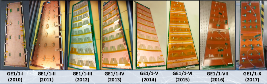
Succesive versions of the GE11 chambers have been built by improving their design in each release. Figure 2 shows the evolution of the GE11 detectors since 2010, when the CMS Collaboration proposed their use in the muon end-cap region of the CMS detector. The latest version is generation-X whose design is discussed in Section 3. The mechanical constraints in the GE11 station require two trapezoidal types of detectors to be used to obtain maximum detection coverage. Long chambers GE11-L have a length of 128.5 cm and short chambers GE11-S have a length of 113.5 cm. The technical details of Short and Long versions, their construction and layout, can be found in [2]. Two identical GE11 detectors are combined to form a “super-chamber” to obtain two detection planes and thus maximize the detection efficiency and the redundancy of the GE11 layer.
2 Impact of GE11 upgrade on CMS
The introduction of the new station known as GE11 will cover the pseudo-rapidity region of CMS [5] and complement the current CSC system. These new chambers are based on GEM technology and can operate at very high rates with good performance. The GE11 station will extend the path length and will provide additional hits that will help to refine the stub reconstruction and improve the momentum resolution. With the new station installed, muon direction will be measured using hit positions in the adjacent GEM GE11 and CSC ME11 chambers. The good position resolution of both the detectors and an increased lever arm formed by the two detectors will allow excellent directional measurement.
FLUKA simulation studies at = 5 1034 cm-2s-1 are used to assess the capability of this new technology to cope with background fluxes expected in the high region [5]. The background rate is estimated from standalone Geant4 simulation, convoluting the fluxes mentioned above with the chamber sensitivities to background. The resulting rate is found to be of order 1 kHzcm2, orders of magnitude below the rate capability limit of the chambers, whose gain is stable up to a few MHzcm2.

Introducing the GE11 muon station will help to reduce the level-1 (L1) muon trigger rates as shown in Figure 3. The distance between adjacent CSCs and GEMs will allow determination of the muon by measuring the bending angle due to the magnetic field in the first muon station alone. This measurement, independent from the one based on the muon bending through the rest of the detector, will allow the maintenance of a low momentum threshold. It will be crucial for a broad spectrum of physics processes whose signatures are characterized by the presence of low muons in the final state. A few examples include the search for the lepton flavor violating decay , Higgs boson decays and , meson decay , and two-Higgs doublet model extended with a scalar singlet (2HDM + S) (Higgs) decay [5].
3 GE11 detector design
A GEM [1] is a 50 m thick copper-clad polymer (Kapton or Apical NP) foil chemically perforated by a high density of microscopic holes. The copper cladding is on both sides of the foil with a thickness of 5 m. The holes in the foil are pierced with double cones with outer diameter 70 m, inner diameter 50 m, and pitch 140 m. Each hole acts as a signal amplifier. Three foils are cascaded to form a detector known as triple GEM to obtain a measurable signal.
The construction of the GE1/1 detectors is shown in Figure 4. The large area GEM foils needed for CMS are produced at the CERN Micro-Pattern Techniques (MPT) workshop using a single-mask production technique [7]. The surfaces of GEM foils oriented towards the readout board are a single continuous conductor whereas the surfaces facing towards the drift board are segmented into sectors each of area about 100 cm2. This segmentation limits the energy of discharges, helping to prevent damage that might be large enough to generate a short. If a short does occur, segmentation reduces the dead area, allowing the rest of the detector to remain sensitive, and reducing the dead time necessary to recharge the affected segment. More details are given in Section 7.


The drift board is a trapezoidal-shaped printed circuit board (PCB) serving as drift electrode. The board has an active area coated with a copper layer and lies within the active gas volume. The readout board is also a trapezoidal-shaped PCB with the inner side of the board featuring 3072 trapezoidal readout strips oriented radially along the longer sides of the detector. All the readout strips are connected through metalized vias to the outer side of the board where traces are routed from the vias to readout pads in 8 3 partitions in (, ) as shown in Figure 4. Each -partition has 384 strips comprised of three 128-strip sectors in . Drift board, readout board, and external frame define the gas volume with gas tightness ensured by an O-ring placed in the groove of the outer frame [2].
4 Gain Measurements
4.1 Test Setup
The detector under test is powered using a programmable high voltage (HV) power supply (CAEN N1470) that allows a controllable current limit (), voltage ramping up and down in steps, maximum voltage, and trip time (the maximum time the current can remain over the controllable limit). The power supply delivers a current up to 1 mA with a monitoring resolution of about 50 nA, which allows identification of unusual current fluctuations. The voltages on the foils are provided through a resistive divider network described in [2]. Measurements are performed by irradiating the detector using a mini AMPTEK X-ray Silver (Ag) target source. The detector is irradiated within a closed copper chamber, the design of which is shown in Figure 5, which prevents radiation exposure to human beings.

The chamber is flushed with a given gas mixture at a flow rate of 5 liters per hour, for at least 5 hours before taking a measurement. Two test gas mixtures, ArCO2 [3] and ArCO2CF4 [4] in proportions of 7030 and 451540, respectively, are used. The choice of CF4 quencher in the latter case is driven by its good timing charateristics [13], non-flammability, and non-corrosivity for metals; it is safer to use than other hydrocarbons such as methane.
The effective gas gain is measured by exposing the detector to an X-ray source with a silver target for generating X-rays. The incident X-rays consist of silver and peaks (centered around the energies of 22 and 25 keV) over an electron bremsstrahlung continuum background. The X-ray photons are absorbed by the copper atoms of the drift electrode which in turn, emits copper X-ray photons of 8 keV energy while returning to the ground state. The X-ray photons emitted by the copper are then converted by the photoelectric effect in the active gas volume. The resulting spectrum is thus a convolution of the energies of the incident X-rays photons interacting in the active gas volume of the detector, the bremsstrahlung continuum background, and a small fraction of unconverted silver and lines. The gain can be measured in each gas composition by comparing the primary current Ip induced in the drift gap by the X-ray source, and the amplified output current (Io) induced on the readout board.
Even though the X-ray photon interaction rate is of order kHz, the primary current is small; it cannot be measured accurately directly from the drift electrode, which is held at high voltage and prone to noise. Instead, the primary current is determined from the product of the count rate (), the number of primary electrons per X-ray photon (), and the electron charge (). The output current from a given sector in (, ) is measured by combining the output from all 128 readout strips in the sector. The combined signal is read out using a charge sensitive pre-amplifier (ORTEC 142PC), followed, in turn, by an amplifier/shaper unit (ORTEC 474), discriminator (Lecroy 623A), and scaler unit. The rate plateau is obtained by ramping up the detector HV. The output current is measured using a pico-ammeter connected to a Keithley Electrometer Model 6487. The data are recorded with a Labview program via a General Purpose Interface Bus (GPIB).
4.2 Results
An example measurement of rate and gain for the (sixth generation) GE11-VI detector is shown in Figure 6 for a gas mixture of ArCO2CF4.
Another example result is shown for a (fourth generation) GE11-IV detector, presented in Figure 7, for the gas mixtures ArCO2 and ArCO2CF4. It is observed that the gain for GE11-IV is higher in ArCO2 compared to ArCO2CF4. Mixtures with carbon tetra-fluoride (CF4) increase the electron drift velocity, improving the detector time resolution, but require higher operating voltages because CF4 is an electron quencher and its addition to ArCO2 reduces the number of electrons participating in the signal formation. Consequently, at comparable voltages, the gain with ArCO2 mixture is higher than that for ArCO2CF4.
Gain measurements for GE11-IV and GE11-VI detectors with gas composition ArCO2CF4 are compared in Figure 7. The gain is seen to be higher for GE11-VI than for GE11-IV; the difference is due to the orientation of the GEM foils. Both GE1/1-VI and GE1/1-IV have single-mask GEM foils with holes that are asymmetrically bi-conical in shape. The holes with the narrow opening facing the incident radiation (chosen for CMS production) show higher gain than when the wider opening of the holes face the incident radiation [10, 11].
Gain uniformity over the active surface of the GE1/1 detectors is one of the crucial parameters for optimal performance. Non-uniformity can result from factors such as variations in hole diameter or variations in gas gap width due to improper stretching; the latter is more important for GE1/1 chambers. Therefore, response uniformity across the surface of all the GE1/1 chambers built in 2017 has been measured by recording the pulse height of every readout strip and is observed to be within 15% [12]. This response uniformity results in efficiency and time resolution that meet operational requirements.
5 Efficiency and Timing Measurements
5.1 Beam Facility
The prototype GEM detectors were tested in the CERN H4 beam, extracted from the SPS (Super Proton Synchrotron). A secondary beam consisting of pions and their decay products is produced when the primary proton beam strikes a beryllium target. The secondary beam is filtered by collimators to produce a beam of muons of energy 150 GeV, which are minimum ionizing particles (MIPs).
5.2 Test Setup
The test setup, shown in Figure 8, consists of a scintillator hodoscope for triggering, a GEM tracking system to reconstruct the muon trajectory, and the GE1/1 chamber under test. A movable aluminum support structure enables translations in and directions to allow beam alignment with different GE1/1 readout sectors. The test beam setups used in earlier test campaigns can be found in [8, 9, 14].
The trigger counters S1, S2, and S3 are organic plastic scintillators with discriminated outputs. A trigger is formed from their triple-coincidence.
The tracking telescope, developed by the RD51 Collaboration [8], consists of three 10 cm 10 cm GEM detectors with strip-based two-dimensional readout planes. The GE11 chambers are aligned perpendicular to the direction of the muon beam and placed downstream of the tracking telescope. The chambers are shielded with aluminum and copper clad foils to reduce the noise level to below that of the expected signals.


5.3 Readout Electronics
The GE1/1 chamber has 3072 readout strips which are organised in groups of 128 to form 8 3 (, ) sectors. The signals are read out by the Application Specific Integrated Circuit (ASIC) VFAT2 [15, 16], a digital front end chip (Figure 9 (top)) originally developed by the TOTEM Collaboration [17]. The chip has 128 readout channels, each connected to a pre-amplifier, shaper, and constant fraction discriminator. The VFAT2 chip provides a binary output with a variable latency for the position information and a fixed latency output, called the SBIT, for time information.
The VFAT2 is controlled by TURBO cards, a stand-alone portable control and data acquisition platform developed for TOTEM Test Platforms [18] for the VFAT2. Each TURBO card can accommodate up to 8 VFAT2 chips. The trigger signal is sent to a master TURBO card. The output from the master TURBO card acts as an input to the slave TURBO card. Both cards receive GEM signals from the VFAT2 chips connected to the tracker and GE1/1 chambers. The TURBO boards are controlled through Labview.
The output from (, ) sector (5, 2) is sent to the shaper of the VFAT2 and then compared to a customizable threshold that was set to 1.2 fC, selected to optimize the process of data acquisition in noisy environments.
5.4 Efficiency
Efficiency, which represents the probability to record an event when a particle crosses the detector, is estimated by recording the total number of triggers generated by the coincidence of the three scintillators and the number of hits , generated by a test region. However, due to possible misalignment of the test region and particle scattering, the number of hits are also observed from neighboring regions. Therefore, the efficiency is calculated by removing these additional hits from the total number of triggers using the formula
The efficiency of the GE11 chambers is measured for the gas mixtures ArCO2 (7030) and ArCO2CF4 (451540) as a function of drift bias. An average efficiency plateau of over 98 is reached at lower voltages for the ArCO2 gas mixture compared to ArCO2CF4 corresponding to effective gains of as shown in Figure 9. The drift bias to reach the efficiency plateau is lower for the gas mixture without CF4 due to the quenching effect of CF4, as discussed in section 4.2.

5.5 Time Resolution
Time resolution is an essential parameter because the GE11 detectors, used both in the CMS trigger and off-line reconstruction, must identify the correct bunch crossing. Several factors determine the time resolution. There are unavoidable fluctuations in the position of the primary ionization cluster formed in the drift region in which the electric field strength determines the drift velocity. There is charge diffusion in the gaps between the GEM foils which can be reduced by the addition of a gas component with low diffusion coefficient such as CF4. The time resolution is measured by the standard deviation of the distribution of the time difference between the trigger and detector signal. The trigger coincidence signal is sent to the common stop input of a CAEN model V775 TDC and the latency output of the detector is sent to a TDC input.
Measurements are shown in Figure 9 for a GE11-IV detector with gas compositions of ArCO2 and ArCO2CF4. The time resolution primarily depends upon the drift voltage at a constant value of transfer and induction fields. Because the chambers were powered using a divider chain [2], the relative strengths of all of the fields were fixed. Therefore, to compare the time resolution achieveable between the two gas mixtures, the measured time resolution is determined as a function of gain, shown in Figure 10, using fits of time resolution versus drift voltage, shown in Figure 9 (bottom). As seen in Figure 10, there is an improvement of by adding a CF4 component to ArCO2. The CMS Region shows the time resolution for the operating conditions expected in CMS.
6 Rate Capability
The flux in the CMS end-caps is not expected to exceed 10 kHz/cm2 and the nominal operating gain of a GE11 detector is expected to be 7 [5]. Using an intense source of X-ray photons, the rate capability is assessed by measuring the gain as a function of rate. The amplified current is measured using a pico-ammeter connected to the anode of the detector as the incident particle flux is varied using copper attenuators. The measurements (Figure 10 (bottom)) show that the effective gain of a full-size GE11-IV detector remains stable up to several hundreds of kHZ/cm2. Measurements are also shown for a 10 cm 10 cm test detector with mm gap configuration at a starting gain of 1.5 104 in Ar/CO2 (70/30) [10, 20]. The effective gain remains stable up to 105 kHz/cm2.
7 Discharge Probability
The GE11 detectors will operate at sufficiently high gain () to ensure maximum detection efficiency while maintaining timing performance. However, with high gains, intense particle fluxes, and densely ionizing particles, the probability increases for producing discharges that could damage the detectors. Discharges are initiated when local charge exceeds the Raether limit [22], resulting in variations in the local electric field. These variations can transform the avalanche into a streamer that propagates in both directions toward GEM electrodes and provokes electrical breakdown of the gas. However, several features of the chamber design reduce the probability of a discharge and limit the damage from those that occur, as previously established [21]. These features, discussed below, are the asymmetric distribution of charge-amplifying electric fields over the three GEM foils, sectorization of the GEM foils, and use of protection resistors to limit the available energy in case of a discharge,
The three amplification stages of a GE11 chamber are set to slightly different gains by applying different voltages across the foils. The voltage across the first GEM foil is 3 higher than the second GEM foil, which itself is 5 higher than the third foil. This configuration significantly reduces the probability of discharge because of the gain sharing between the three amplification stages. Furthermore, because of separate amplification stages and an independent readout plane, the propagation of a streamer before further amplification is considerably diminished and the probability is reduced for inducing large signals on the readout board, preventing damage to the detector and electronics.
The GEM foils are designed to reduce damage from discharges. The electrodes facing the drift plane are divided into several sectors, each with an area 100 cm2 and each sector with a 10 M protection resistor. In case of a discharge, the current flowing through the resistor will induce a voltage drop across it, limiting the energy of a discharge and reducing its propagation.
The discharge probability is measured for a third generation GE1 [5] detector and, separately, for a 10 cm 10 cm test detector with the same gap configuration as a GE11 detector [20]. In each case, gain is set to extremely high values ranging from 4 to 6 . The detectors are irradiated by densely ionizing -particles from a 241Am source. The measured discharge probability versus gain for a GE11-III detector is shown in Figure 11. The data are also displayed as discharge probability versus drift potential, with the CMS Region indicated. Because an alpha particle from 241Am produces nearly a hundred times more primaries than a MIP, the discharge probability for a MIP must be divided by this factor. In the CMS Region this probability is less than 10-12, well within the requirements for the GE1/1 system.
8 Fits to Data and Summary
To characterize the performance of a GE11 chamber for any drift voltage, the data for gain, discharge probability, efficiency, and time resolution are fit with parametric equations as shown in Table 1. The fits provide a good description of the data and allow interpolation to any desired value of drift voltage. Interpolated data points are obtained for the measured quantities and are displayed in the master plots of Figures 12 and 13 for ArCO2 and ArCOCF4 gases, respectively. The CMS Region, shown as a shaded area in the figures, corresponds to the operational regime for the CMS experiment.
| Gas | Property | a | b | c | Fit Equation |
| Ar/CO2 | Gain | 270.85 | -22.72 | 0.007 | |
| Efficiency | 0.983 | 2885.12 | 62.59 | ||
| Time Resolution | 78.48 | 2346.92 | 441.1 | ||
| Discharge Probability | 0 | 0.013 | |||
| Ar/CO2/CF4 | Gain | 4336.03 | -26.27 | 0.0068 | |
| Efficiency | 0.99 | 3502.37 | 50.78 | ||
| Time Resolution | 39.21 | 3126.77 | 428.09 | ) | |
| Discharge Probability | 0 | 0.009 |
In summary, different generations of GE11 detectors are tested for gain, efficiency, time resolution, and discharge probability with gas compositions of ArCO2 and ArCOCF4. The measurements show that a GE11 detector can be operated up to a gain of about with a discharge probability of less than under CMS operating conditions with a MIP rate up to 106 Hz. The performance of the chamber in beam tests shows an efficiency of 98 or better obtained across the active area, and time resolution close to 5 ns.
Acknowledgements
We gratefully acknowledge the support from FRS-FNRS (Belgium), FWO-Flanders (Belgium), BSF-MES (Bulgaria), BMBF (Germany), CSIR & UGC (India), DAE (India), DST (India), INFN (Italy), NRF (Korea), LAS (Lithuania), QNRF (Qatar), DOE (USA) and the RD51 collaboration.
References
- [1] F. Sauli, A new concept for electron amplification in gas detectors, Nucl. Instrum. Meth. A. 386 (1997) 531.
- [2] D. Abbaneo et al., Layout and assembly technique of the GEM chambers for the upgrade of the CMS first muon endcap station, Nucl. Instrum. Meth. A. 918 (2019) 67-75.
- [3] F. Sauli, The gas electron multiplier (GEM): Operating principles and applications, Nucl. Inst. and Meth. A 805 (2016) 2-24.
- [4] G. Bencivenni et al., Advances in triple-GEM detector operation for high-rate particle triggering, Nucl. Inst. and Meth. A 513 (2003) 264–268.
- [5] CMS Collaboration, CMS Technical Design Report for the Muon Endcap GEM Upgrade, CERN-LHCC-2015-012 (2015).
- [6] CMS Collaboration, The Phase-2 Upgrade of theCMS Muon Detectors, CERN-LHCC-2017-012; CMS-TDR-016 22/10/2018.
- [7] S. D. Pinto et al., Progress on large area GEMs, JINST 4 (2009) P12009.
- [8] D. Abbaneo et al., Test Beam Results of the GE11 Prototype for a Future Upgrade of the CMS high- muon system, IEEE, Nucl. Sci. Symp. (2011), and RD51-Note-2011-013.
- [9] D. Abbaneo et al., Characterization of GEM Detectors for Application in the CMS Muon Detection System, RD51-Note-005 (2010).
- [10] A. Shah et al., Impact of Single-Mask Hole Asymmetry on the properties of GEM Detectors, Nucl. Instrum. Meth. A 936 (2019) 459-461.
- [11] J. A. Merlin, GEM single-mask characterization and influence of GEM foil orientation, MPGD (2017).
- [12] D. Abbaneo et al., Operational Experience With the GEM Detector Assembly Lines for the CMS Forward Muon Upgrade, IEEE Trans. Nucl. Sci. 65 (2018) 11.
- [13] M. Alfonsi et al., Operation of triple-GEM detectors with fast gas mixtures, Nucl. Instrum. Meth. A. 488 (2002) 493.
- [14] D. Abbaneo et al., Beam Test Results for New Full-scale GEM Prototypes for a Future Upgrade of the CMS High-eta Muon System, IEEE Nucl. Sci. Symp. (2012).
- [15] P. Aspell et al., VFAT2: A front-end system on chip providing fast trigger information, digitized data storage and formatting for the charge sensitive readout of multi-channel silicon and gas particle detectors, RD51-Note-007 (2007).
- [16] D. Abbaneo et al., The status of the GEM project for CMS high- muon system, Nucl. Instrum. Meth. A 732 (2013) 203.
- [17] G. Anelli et al., The TOTEM experiment at the CERN Large Hadron Collider, 3 JINST (2008) S08007.
- [18] P. Aspella et al., The VFAT Production Test Platform for the TOTEM Experiment, CERN, Topical Workshop on Electronics for Particle Physics (2009).
- [19] D. Abbaneo et al., Charged Particle Detection Performance of Gas Electron Multiplier (GEM) Detectors for the Upgrade of CMS Endcap Muon System at the CERN LHC, IEEE Nucl. Sci. Symp. (2015), CERN NOTE-04.
- [20] J. A. Merlin, Study of long-term sustained operation of gaseous detectors for the high rate environment in CMS, CERN-THESIS-2016-041 (2016).
- [21] S. Bachmann et al., Discharge Studies and Prevention in the Gas Electron Multiplier (GEM), Nucl. Instrum. Meth. A 479 (2000) 294.
- [22] H. Raether, Electron avalanches and breakdown in gases, CERN NOTE-191 (1964).