Fast and Accurate Reconstruction of Pan-Tilt RGB-D Scans via Axis Bound Registration
Abstract
A fast and accurate algorithm is presented for registering scans from an RGB-D camera on a pan-tilt platform. The pan-tilt RGB-D camera rotates and scans the entire scene in an automated fashion. The proposed algorithm exploits the movement of the camera that is bound by the two rotation axes of the servo motors so as to realize fast and accurate registration of acquired point clouds. The rotation parameters, including the rotation axes, pan-tilt transformations and the servo control mechanism, are calibrated beforehand. Subsequently, fast global registration can be performed during online operation with transformation matrices formed by the calibrated rotation axes and angles. In local registration, features are extracted and matched between two scenes. For robust registration, false-positive correspondences are rejected based on their distances to the rotation trajectories. Then, a more accurate registration can be achieved by minimizing the residual distances between correspondence pairs, while estimated transformations are bound to the rotation axes. Results of comparative experiments validate that the proposed method outperforms state-of-the-art algorithms of various approaches based on camera calibration, global registration, and simultaneous-localization-and-mapping in terms of root-mean-square error and computation time.
1 Introduction
Indoor scene reconstruction is of crucial importance in various research areas, in which 3D geometry data is required, such as robotics, architecture, and augmented reality. More specifically, in robotics, 3D map data is required for a robot to localize itself, plan a path, and navigate to a specific location as ordered. The practice of this localization and mapping is often abbreviated as SLAM (Simultaneous Localization and Mapping). In architecture, indoor scenes are reconstructed, so that users can navigate virtually, and are then exported as CAD files for users to correct reconstruction errors and further edit to meet their needs (Ikehata et al. 2015). In conjunction with augmented reality (AR), reconstructed models are used as surface geometry for projection-based AR, where geometric distortions are corrected to deliver pure immersive AR experience (Wilson et al. 2012).
In general, RGB depth (RGB-D) cameras are hand-held by the user and are moved freely around the environment to map and reconstruct the geometry of indoor scenes, particularly for SLAM applications (Sturm et al. 2012). However, in various cases, RGB-D cameras are attached to pan-tilt rotating platforms and collect 3D data captured in pan-tilt sweeps (Wilson et al. 2012; Naweed et al. 2014; Ambruş et al. 2014). Using pan-tilt platforms with RGB-D cameras has several advantages. Firstly, the field-of-view of the cameras is limited, when a wide range of data should be captured from the environment. In such a case, steering the camera with a pan-tilt unit would be preferred (Niu et al. 2017), over noisy hand-held alternatives. Secondly, the detection range and resolution of the RGB-D camera may be limited to capture the geometry of even a standard-sized room. Thus, given that the scene is stationary, using a pan-tilt RGB-D camera to capture the room from its center, would be an ideal option (Naweed et al. 2014). Lastly, as the scanning and capturing process can be automated and computer-controlled (Ambruş et al. 2014), it would be more convenient and accurate to use pan-tilt RGB-D cameras.
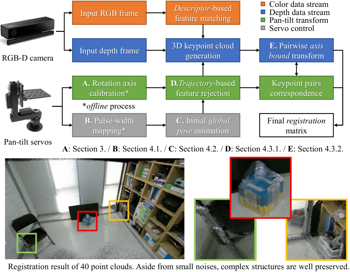

As SLAM methods can perform localization of the camera that is freely moving and mapping of the environment at the same time, some pan-tilt setups adopts SLAM methods for such purposes. For example, in Wilson et al. 2012, KinectFusion (Newcombe et al. 2011) was used to reconstruct the surface geometry for steerable projection AR. However, many SLAM methods are based on iterative closest point (ICP) or bundle adjustment (BA) methods, which are still computationally heavy for non-high-end computers. In this study, a fast and accurate registration algorithm, namely axis bound registration, is proposed to reconstruct indoor environments with pan-tilt RGB-D cameras. The overall process of the proposed method is shown in Figure 1. When compared to other state-of-the-art registration and SLAM methods, the proposed algorithm is able to produce better registration results in much shorter time. We summarize the contributions of the presented paper as follow:
- 1.
Rotation axis calibration and servo control scheme are incorporate into registration algorithm to roughly estimate the global pose of the camera (Figure 3).
- 2.
A novel rotation trajectory-distance constraint is developed to robustly reject outlier keypoints, and to further refine the estimated pose without RANSAC (Figure 2).
- 3.
2 Related Work
2.1 Steerable Platform Calibration
Pan-tilt–zoom (PTZ) cameras have long been used for surveillance, object tracking and so forth. Davis and Chen 2003 presented a calibration model where the typical pin-hole camera model was extended to incorporate the characteristics of pan and tilt motions. In Wu and Radke 2013, Wu and Radke proposed a camera model involving not only pan and tilt motions but also zoom on the image domain.
A calibration method for a rotating turntable using external camera was introduced in Chen et al. 2014. The method was later extended by Niu et al. 2017, where the camera was attached to a rotating plate. The method was also incorporated in Byun et al. 2018, which proposed a control mechanism for the motion and orientation of a generalized pan-tilt camera. Combining rotation axis calibration and camera-servo control, the study adopted the inverse kinematics approach to accurately interpret and manipulate the camera motion.
Tsai and Huang 2017 took an approach that is similar to the proposed method, in that the pan-tilt system was used to estimate the current pose of the camera. Multi-view calibration was performed to construct the database of transformations at each preset pan-tilt rotation. Later, the transformations were looked up from the database to seed the ICP algorithm for point cloud registration. However, the method is limited in terms of scalability, as the method cannot estimate the pose of the camera when the pan-tilt platform rotates to unseen positions.
2.2 Point Cloud Matching
Super 4-points congruent sets (Super4PCS) (Mellado et al. 2014) and fast global registration (FGR) (Zhou et al. 2016) are examples of global registration methods, which globally search the point correspondences between two point clouds of any condition. The authors of (Mellado et al. 2014) proposed a novel method for removing the quadratic time complexity of its predecessor in (Aiger et al. 2008). The key idea behind this improvement is the use of the data structure in solving the core instance problem, where the goal is to find all candidate pairs of a given point that are within a distance range. FGR optimizes an objective function involving candidate matches over the surface of the object scans to align surfaces. The authors argue that the method does not require initialization, yet it can achieve accuracy comparable to that of well-initialized local refinement algorithms. Both global registration methods are compared with the proposed method in Section 5.
2.3 Localization and Mapping
Research in the SLAM field focuses on positional, orientational tracking of the camera and reconstruction of the scene in tandem. As mentioned above, some SLAM methods rely on the ICP algorithm (Besl et al. 1992) to track the pose of the camera. For example, KinectFusion (Newcombe et al. 2011) and Endres et al. 2014 tracks the pose of the camera by repeatedly revising the transformation to minimize the difference between two clouds of points based on ICP.
The iterative nature of the ICP method makes SLAM algorithms inherently heavyweight in terms of computing resources, such as power and memory consumption. Thus, several ICP-based SLAM methods is able to perform in real-time only with the assistance of GPU (Neumann et al. 2011). Newcombe et al. 2011, Endres et al. 2014 and Whelan et al. 2016, all make significant use of the GPU computation for mapping construction as well as tracking and pose estimation.
To tackle the heavy computation of ICP, ORB-SLAM2 (Mur-Artal and Tardós 2017) was proposed. The algorithm adopted BA method instead of ICP, which was sufficiently lightweight to perform sparse reconstruction with a standard CPU. However, even ORB-SLAM2 relies on CPU multi-threading, OpenMP, to achieve real-time performance. Without multi-threading, the performance degraded to 4 frames per second (Table 1 and 2).
3 Pan-Tilt Rotation Calibration


The proposed method takes into account the pan-tilt platform that controls the camera movement. Thus, the rotation parameters of the pan-tilt servos are first calibrated, which are depicted in Figure 3. The steps in Byun et al. 2018 are followed to recover their parameters for the rotation model.
Rotating points around a rotation axis forms closed circular trajectories, which is represented as great circles on 3-dimensional planes. Thus, by fitting planes and circles the rotation direction vector and its center can be estimated. The calibration starts by setting the initial frame as the reference frame. Then, images of the checkerboard placed against the wall are captured while the camera rotates using pulse width modulation (PWM), from one end of the field-of-view to another. Since the geometric relations of checkerboard corners are pre-known, all rotation trajectories can be represented relative to that of the top-leftmost corner in the reference frame. Finally, the aggregated corners from multi-view checkerboard frames are used to obtain rotation parameters of Figure 3 using all corner points with constrained global optimization (Chen et al. 2014).
Formally, the pan-tilt transform is modeled as follow. Let the rotation direction vector be defined as , with its norm being , and the rotation center for the upper-left corner be defined as . With all the parameters of and rotations calibrated, the corresponding coordinates of 3D points between a local camera frame and the reference frame can now be represented. If the and angles of the local frame are denoted by and respectively, and the local point by , its coordinate in the reference frame can be modeled as follows:
| (1) |
Here, is a matrix representing the rotation around a axis vector and is a translation matrix of the position of the rotation axis . Any point on the line of the rotation axis can be a pivot for the rotation, which does not affect the final transformation. Here, the center of the rotation of the upper-leftmost corner of the checkerboard was used. The same representation applies to both the and transforms.
4 Pan-Tilt Axis Bound Registration
4.1 Camera Transformation with Servo Control
The proposed method roughly estimates the camera’s pose based on the servo control. Potentiometers, which servos use to orient themselves, rotates linearly to the applied pulse width. Therefore, it is possible to estimate the rotated angle of the pan-tilt platform based on the width of the applied pulse. With rotation angles and applied pulse widths computed during calibration, a linear system can be constructed to estimate the rotated angle of the pan-tilt platform based on PWM as follows:
| (2) |
Solutions for the above equation can be conveniently obtained by minimizing the sum of squared errors using Singular Value Decomposition (SVD). Figure 4 (a) depicts the linear mapping result between the pulse widths and rotation angles.
We further refine the angle estimation, by modeling the residual of the estimation (Figure 4 (b)) as Gaussian noise (Figure 4 (c)). The result of a Shapiro-Wilk test for normality (Shapiro and Wilk 1965) strongly support that the residual distribution is normal, since p-value =.05 (W=.982, df=28 p=.898).
This is to compensate for two servo errors, namely the mechanical error and the random error, as categorized by Wu and Radke 2013. The mechanical error refers to errors in angle estimation due to servo’s manufacturing quality such as Figure 4 (b). To compensate for mechanical errors, Chao et al. 2014 added an additional error compensation term and used the spline curve for modeling such errors.
However, fitting raw errors to a fixed curve model cannot handle the other source of the error, which is the random error. As demonstrated in Figure 4 of Wu and Radke 2013, a servo motor randomly deviates from its supposed position throughout continuous operation. Such random errors with the pan-tilt system were also experienced in this study, as shown in Figure 5. Considering the randomness nature of the errors, we modeled the angular errors as Gaussian noise occurring to the linear mapping between the pulse width and the rotation angle.


4.2 Global Registration
The rotation platform of the camera system is governed by two pan-tilt servos, which are controlled according to the width of the applied pulse. Thus, by formulating the rotation angles and transformation model of the pan-tilt servos, the overall transformation of the camera system can be identified. The rotation angle can be estimated by inputting the pulse width to Equation 2, which is then substituted into Equation 1, yielding the initial transform matrix.
The transform matrix is an estimation of the camera pose rotated by the pan-tilt servos. Thus, the matrix can be used to register point clouds of multiple local frames in the common global frame. However, as shown in Figure 4, the presence of random errors in the pan-tilt servos indicates that the transformation obtained is still a coarse estimation and should be refined further. We compensate for the impact of such errors modeled as Gaussian noise in the local registration.
4.3 Local Registration
4.3.1 Outlier Rejection with Rotation Trajectory Prior
In pairwise local registration, feature matching between adjacent frames is performed. However, simple matching of feature descriptors often suffers from false positives and outliers. Although the random sample consensus (RANSAC) method is commonly employed to resolve this issue, the iterative nature of random sampling inevitably requires expensive computation, but still cannot guarantee the correct result. Thus, we propose a rejection method for outlier matches by leveraging the prior knowledge of the rotation trajectory obtained in Section 4.1.
Let the first and second frames of a given pair be denoted by and , respectively. A frame consists of a color image and corresponding depth data. To start with, we establish a set of putative correspondences by extracting keypoints and matching their descriptors from color images, using ORB (Rublee et al. 2011). Using the depth data, the keypoint pairs in the image domain are then projected to each local camera frame. 3D points of the -th keypoint pair in the set are denoted by and . From Equation 2, pan and tilt angles of each frame can be acquired, namely , , and . Substituting , , into Equation 1 yields pre-oriented 3D points in the global frame, denoted by as follows:
| (3) |
Given pre-oriented keypoint pairs and , we determine whether they are falsely matched or not based on their distances to the rotation trajectory, as illustrated in Figure 2. Specifically, the indicator function declares that the matching of and is a false positive if the distance exceeds a certain limit, namely , as follows:
| (4) |
The value of is dynamically imposed for each point. We first consider that the estimated rotation angles (Equation 2) exhibit Gaussian-distributed errors. Given the standard deviation , we allow range of deviation for the estimated rotation angle. As Pr for a normally distributed random variable, we assume that estimations that deviate more than the slack are outliers. Since the camera rotates around the circular trajectory, the distance between rotated points can be approximated as the arc length. Thus, for a true-positive match, , where is the distance of a point from the camera and is the maximal allowed angular deviation in radian. In the proposed setup, is set as , and as , considering the value in Figure 4.
4.3.2 Pairwise Transform with Axis Bound Registration
In pairwise registration, the objective of local registration is to determine the pan-tilt angles and of the frame , seeded from Equation 2, that transforms to its correspondence of the frame , while and are fixed. Note that is a local point, whereas is pre-oriented as in Equation 3. Formally, the cost function for the local registration is constructed to minimize the distances between correspondence pairs as follow:
|
|
(5) |
The transformation regarding the cost function is bound by the two rotation axes, and , hence the name Axis Bound Registration of the proposed algorithm. The cost function (Equation 5) is a non-linear optimization problem about two trigonometric variables and . Though the Levenberg-Marquardt method is commonly employed to solve the non-linear problem, iterative methods often hinder real-time performance. Thus, we instead adopt alternating optimization partially linearize and accelerate the problem solver.
Let denote the given value for the tilt rotation. Then by the rotation transformation of Equation 1, the cost function Equation 5 can now be divided into the function for the rotation angle as follows:
| (6) |
Similarly, denotes the given value for the pan rotation and the sub-function for the rotation angle is constructed as follows:
| (7) |
The superscripts of and are omitted for visibility. are all 13 column vectors denoting coordinates in the 3D space. and are introduced to respectively incorporate known rotations of and .
Each sub-cost function can be iteratively solved in closed form, in each alternating step. However, albeit empirically in the experiment (Section 5), we found that a single alternation sufficed to yield numerically optimal solutions.
To solve for Equations 6 and 7, we rearrange all terms of , , into matrix expressions in the form of to construct two linear systems, where and for , and and for . Due to limited space, exact formulas for are shown in the supplementary materials.
Both and can be solved by the SVD method, which yields least squares error solutions for , and . The initial solutions are refined to obtain the actual rotation angles of interest by enforcing trigonometric properties, that is and . The and angles define the pairwise transformation from frame to in space, which finalizes registration between two frames.
5 Experiment and Evaluation


5.1 System and Dataset Configuration
To validate the proposed method, an experimental environment was set up comprising an RGB-D camera and two pan-tilt servos, supported by a steerable platform as shown in Figure 6. The steerable platform was assembled from custom-made arms and gears, where two servos were attached to rotate the platform in pan and tilt directions. Two HS-785HB servo motors were used, which accept – microseconds pulse width. Microsoft Kinect v2 was used, for RGB and time-of-flight depth images.
Since the proposed approach combines servo control and camera pose estimation for point cloud registration, calibration data, including rotation axes and pulse width mapping, are required. However, to the best of the authors’ knowledge, there is no publicly available dataset that meets all the requirements for pan-tilt RGB-D scan registration, including the dataset of Tsai and Huang 2017, which used a similar pan-tilt camera setup. Therefore, the pan-tilt RGB-D scan dataset was constructed in-house, the sequences of which are shown in Figure 7.
5.2 Pan-Tilt RGB-D Scan Registration

The proposed method was compared with four state-of-art methods that used different approaches. The first is the RGBD-Calib (Tsai and Huang 2017), which makes use of external parameters of the camera for pose estimation and used ICP algorithm to refine the poses. Two other methods are FGR (Zhou et al. 2016) and S4PCS (Mellado et al. 2014), which were compared with the RGBD-Calib method in Tsai and Huang 2017. Both methods are global registration methods, which register two point clouds by searching for global point correspondences. The last method for comparison is ORB-SLAM2 (Mur-Artal and Tardós 2017). ORB-SLAM2 is one of the most prominent SLAM methods, which performs pose estimation of a RGB-D camera, as well as a sparse 3D reconstruction. Though ORB-SLAM2 supports CPU multi-threading, multi-threading option was disabled in the experiments for fairness as all other methods run in a single process/thread.
To quantitatively measure the performance of the registration results, the RMS metric of closest points was used as in Tsai and Huang 2017. Given points in the input point cloud, or frame , their closest points are determined in the source point cloud, or frame . If the vector storing the vector distances (in millimeters) between closest point pairs is denoted by and its -th element by , the RMSE is defined as
| (8) |
All experiments were conducted on a Windows 10 with Intel Core i7-6700K CPU @ 4.00 GHz and 16 GB of DDR4 memory. For image processing and camera calibration, the OpenCV library (Bradski 2000) was used. For ICP algorithm and closest points RMSE implementation, the PCL library (Rusu and Cousins 2011) was used. All codes were written in C++ and compiled with the O2 optimization and no multi-threading.
5.3 Experiment, Evaluation, and Analysis
Figure 7 shows two datasets for the registration experiments. Named after the room number, D815 and D816, the datasets consist of 30 frames each, created by by rotating the camera in pan direction by 1.5° at each step, with arbitrary tilt angles. To make the most of the limited number of scan data, the experiment was conducted with 6 partitions of the dataset, consisting of 5 frames, 10 frames, 15 frames and 30 frames, yielding total 12 test cases for each dataset.
For the quantitative evaluation, the registration results in terms of registration error and execution time are summarized in Table 1 (D815), and in Table 2 (D816). For the visual comparison, the registration images of the experiment are available as Figure A.1–A.12 (D815) and Figure B.1–B.12 (D816) in the supplementary material. We emphasize that a fair amount of time was devoted to adjusting parameters for each algorithm, particularly for FGR and S4PCS, to optimize the algorithm in terms of RMSE. Moreover, the termination conditions of ICP for RGBD-Calib were also optimized.
5.3.1 Experiment on Dataset D815
In terms of registration error, the proposed algorithm outperformed other algorithms in 19 cases out of all 21 test cases, and ranked second in the other 2 cases. In terms of speed, the proposed algorithm was the apparently fastest in all 21 test cases, followed by the second fastest ORB-SLAM2.
It is notable that in many cases, the proposed method was up to more than twice as fast as the second ranked ORB-SLAM2, which is a BA-based SLAM method, while maintaining better performance in all but one test cases. Also, the proposed method always outperformed RGBD-Calib, which is ICP-based calibration method, FGR and S4PCS, which are global registration methods, in both error and speed terms. The outperformance of the proposed method indicates that a fast and accurate registration is possible without ICP or BA method, by directly modeling 3D motion trajectories of the actuated camera, and utilizing those information in the registration.
5.3.2 Experiment on Dataset D816
For the experiment D816, the proposed method clearly outperformed other algorithms in all test cases, in terms of both registration error and execution time. Especially, while other algorithms took substantially longer time than the D815 results, the proposed method maintained almost consistent speed, which highlights the proposed method’s fast and accurate registration. We conjecture that texture-less surfaces and repeated structures of the dataset D816, required algorithms of more complex estimations and much longer time. Thus, it would be safe to say that when compared to other RANSAC, ICP or BA-based registration algorithms, the proposed algorithm was able to produce more accurate registration results in much shorter time, by incorporating the rotation of the camera that is bound by the two axes of pan-tilt servos into the registration process.
6 Conclusion
In this paper, we proposed Axis Bound Registration, which is an accurate and fast method for registering RGB-D scans of a pan-tilt camera. We incorporated rotation axis calibration and camera-servo control to register point clouds of two frames. Utilizing the prior knowledge on the rotational motion of the pan-tilt servos, a distance-to-rotation-trajectory constraint was introduced to robustly reject falsely matched pairs without iterative RANSAC process. The rotational model is used to construct an objective function that minimizes the point-to-point errors for transform estimation. The alternating optimization scheme is adopted to divide and linearlize the objective function into two independent problems, which accelerates the solver. In the experiments, the proposed method was compared with, and outperformed four other ICP or BA-based state-of-the-art registration algorithms, in terms of RMSE and execution time.
References
- Aiger et al. [2008] Dror Aiger, Niloy J Mitra, and Daniel Cohen-Or. 4-points congruent sets for robust pairwise surface registration. In ACM Transactions on Graphics (TOG), volume 27, page 85. ACM, 2008.
- Ambruş et al. [2014] Rareş Ambruş, Nils Bore, John Folkesson, and Patric Jensfelt. Meta-rooms: Building and maintaining long term spatial models in a dynamic world. In Intelligent Robots and Systems (IROS 2014), 2014 IEEE/RSJ International Conference on, pages 1854–1861. IEEE, 2014.
- Besl et al. [1992] Paul J Besl, Neil D McKay, et al. A method for registration of 3-d shapes. IEEE Transactions on pattern analysis and machine intelligence, 14(2):239–256, 1992.
- Bradski [2000] G. Bradski. The OpenCV Library. Dr. Dobb’s Journal of Software Tools, 2000.
- Byun et al. [2018] Jung-Hyun Byun, Seung-Ho Chae, and Tack-Don Han. Accurate Control of a Pan-tilt System Based on Parameterization of Rotational Motion. In EG 2018 - Short Papers. The Eurographics Association, 2018.
- Chao et al. [2014] Chen Chao, Shen Lincheng, Zhou Dianle, Zhang Daibing, and Zhong Zhiwei. Vision-based pan-tilt unit error measurement. In Electronics, Computer and Applications, 2014 IEEE Workshop on, pages 92–96. IEEE, 2014.
- Chen et al. [2014] Ping Chen, Min Dai, Kai Chen, and Zhisheng Zhang. Rotation axis calibration of a turntable using constrained global optimization. Optik-International Journal for Light and Electron Optics, 125(17):4831–4836, 2014.
- Davis and Chen [2003] James Davis and Xing Chen. Calibrating pan-tilt cameras in wide-area surveillance networks. In In IEEE International Conference on Computer Vision. Citeseer, 2003.
- Endres et al. [2014] Felix Endres, Jürgen Hess, Jürgen Sturm, Daniel Cremers, and Wolfram Burgard. 3-d mapping with an rgb-d camera. IEEE Transactions on Robotics, 30(1):177–187, 2014.
- Ikehata et al. [2015] Satoshi Ikehata, Hang Yang, and Yasutaka Furukawa. Structured indoor modeling. In Proceedings of the IEEE International Conference on Computer Vision, pages 1323–1331, 2015.
- Mellado et al. [2014] Nicolas Mellado, Dror Aiger, and Niloy J Mitra. Super 4pcs fast global pointcloud registration via smart indexing. In Computer Graphics Forum, volume 33, pages 205–215. Wiley Online Library, 2014.
- Mur-Artal and Tardós [2017] Raúl Mur-Artal and Juan D. Tardós. ORB-SLAM2: an open-source SLAM system for monocular, stereo and RGB-D cameras. IEEE Transactions on Robotics, 33(5):1255–1262, 2017. doi: 10.1109/TRO.2017.2705103.
- Naweed et al. [2014] Asad Ullah Naweed, Lu Chen, Mingsong Dou, and Henry Fuchs. Enhancement of 3d capture of room-sized dynamic scenes with pan-tilt-zoom cameras. In International Symposium on Visual Computing, pages 379–389. Springer, 2014.
- Neumann et al. [2011] Dominik Neumann, Felix Lugauer, Sebastian Bauer, Jakob Wasza, and Joachim Hornegger. Real-time rgb-d mapping and 3-d modeling on the gpu using the random ball cover data structure. In Computer Vision Workshops (ICCV Workshops), 2011 IEEE International Conference on, pages 1161–1167. IEEE, 2011.
- Newcombe et al. [2011] Richard A Newcombe, Shahram Izadi, Otmar Hilliges, David Molyneaux, David Kim, Andrew J Davison, Pushmeet Kohi, Jamie Shotton, Steve Hodges, and Andrew Fitzgibbon. Kinectfusion: Real-time dense surface mapping and tracking. In Mixed and augmented reality (ISMAR), 2011 10th IEEE international symposium on, pages 127–136. IEEE, 2011.
- Niu et al. [2017] Zhenqi Niu, Kuo Liu, Yuemin Wang, Shujun Huang, Xiaoting Deng, and Zonghua Zhang. Calibration method for the relative orientation between the rotation axis and a camera using constrained global optimization. Measurement Science and Technology, 28(5):055001, 2017.
- Rublee et al. [2011] Ethan Rublee, Vincent Rabaud, Kurt Konolige, and Gary Bradski. Orb: An efficient alternative to sift or surf. In Computer Vision (ICCV), 2011 IEEE international conference on, pages 2564–2571. IEEE, 2011.
- Rusu and Cousins [2011] Radu Bogdan Rusu and Steve Cousins. 3D is here: Point Cloud Library (PCL). In IEEE International Conference on Robotics and Automation (ICRA), Shanghai, China, May 9-13 2011.
- Shapiro and Wilk [1965] Samuel Sanford Shapiro and Martin B Wilk. An analysis of variance test for normality (complete samples). Biometrika, 52(3/4):591–611, 1965.
- Sturm et al. [2012] J. Sturm, N. Engelhard, F. Endres, W. Burgard, and D. Cremers. A benchmark for the evaluation of rgb-d slam systems. In Proc. of the International Conference on Intelligent Robot Systems (IROS), Oct. 2012.
- Tsai and Huang [2017] Chi-Yi Tsai and Chih-Hung Huang. Indoor scene point cloud registration algorithm based on rgb-d camera calibration. Sensors, 17(8):1874, 2017.
- Whelan et al. [2016] T. Whelan, R. F. Salas-Moreno, B. Glocker, A. J. Davison, and S. Leutenegger. Elasticfusion: Real-time dense slam and light source estimation. Intl. J. of Robotics Research, IJRR, 2016.
- Wilson et al. [2012] Andrew Wilson, Hrvoje Benko, Shahram Izadi, and Otmar Hilliges. Steerable augmented reality with the beamatron. In Proceedings of the 25th annual ACM symposium on User interface software and technology, pages 413–422. ACM, 2012.
- Wu and Radke [2013] Ziyan Wu and Richard J Radke. Keeping a pan-tilt-zoom camera calibrated. IEEE transactions on pattern analysis and machine intelligence, 35(8):1994–2007, 2013.
- Zhou et al. [2016] Qian-Yi Zhou, Jaesik Park, and Vladlen Koltun. Fast global registration. In European Conference on Computer Vision, pages 766–782. Springer, 2016.