Broadband Tunable THz Absorption with Singular Graphene Metasurfaces
Abstract
By exploiting singular spatial modulations of the graphene conductivity, we design a broadband, tunable THz absorber whose efficiency approaches the theoretical upper bound for a wide absorption band with a fractional bandwidth of 185%. Strong field enhancement is exhibited by the modes of this extended structure, which is able to excite a wealth of high order surface plasmons, enabling deeply subwavelength focussing of incident THz radiation. Previous studies have shown that the conductivity can be modulated at GHz frequencies, which might lead to the development of efficient high speed broadband switching by an atomically thin layer.
keywords
broadband absorber, surface plasmons, singular structures, metamaterials, tunable metasurfaces, terahertzWhen suitably doped, graphene supports THz plasmonsBasov et al. 2016; Low et al. 2016, and these can be coupled to incident radiation by periodic modification of the sample either by dopingFang2013; Poumirol2017 or by physical restructuring.Yan2012 Very strong absorption results, approaching the theoretical limit of , but over an extremely narrow range of frequencies, were already demonstrated.Huidobro et al. 2017 In a previous paperPendry et al. 2017 we have shown that singular metasurfaces are qualitatively different from non singular ones. Here we exploit the broadband nature of their spectrum to create an absorber of THz radiation with equally strong absorption but now over a broad band of frequencies and, curiously, in a layer of material a fraction of a nanometre thick. The absorption has the potential to be switched at a high rate, potentially as high as GHz.li2014ultrafast Graphene is a promising platform for nano-optics due to its high sensitivity to external electromagnetic (EM) fieldsBonaccorso et al. 2010; Low and Avouris 2014. Despite being atomically thin, this two-dimensional (2D) material is able to sustain oscillations of its free electrons driven by EM radiation, thanks to the excitation of surface plasmon polaritons.Vafek 2006; Hanson 2008; Jablan et al. 2009; Dubinov et al. 2011; Koppens et al. 2011; Nikitin et al. 2011; Fei et al. 2011 Its high, doping-independent, carrier mobility, Ni et al. 2016; chen2008intrinsic and the possibility of electrical tuning of its Fermi level,Vakil2011; Novoselov2004 make graphene an ideal material for plasmonic applications.GarciadeAbajo2014; Grigorenko2012
Complete light absorption has formerly been realized in a variety of implementations, most often, but not only, exploiting interference effects following the Salisbury screen concept. Multi-layer structures Huidobro et al. 2017; nefedov2013perfect, but also periodic surface patterning zhang2014coherent and other metamaterial configurations thongrattanasiri2012complete; fang2012tunable have shown good results over a narrow absorption band. More recently, the tunability of graphene inspired applications of this material in the design of absorptive metasurfaces.fang2013active; Huidobro et al. 2017 A general theoretical framework for the design of coherent broadband absorbers was recently investigated using scattering matrices.kim2016general. In the near-infrared, perfect broadband absorbers have been recently realized in epsilon-near-zero liberal2017near indium-tin-oxide stacks, achieving absorption over a fractional bandwidth of .yoon2015broadband. In an material, broadband response is characteristic of singular structures. Localized plasmonic structures with sharp edges or touching points have been studied in the past.Luo et al. 2010; Pendry2013; aubry2010broadband In these systems, radiation is captured in their smooth portions, and travels towards the singularities becoming increasingly squeezed. This leads to a continuous rather than discrete far field spectrum. In this work we show such a broadband response for an extended metasurface, rather than for a localized structure.
Applications in plasmonics rely on the capacity of concentrating and delivering electromagnetic energy at the nanoscale.Maier 2007 The large spatial confinement provided by graphene plasmons is highly desirable for this purpose, but at the same time it limits our ability to access and tailor these modes. This has been sorted in the past by using local probes,Fei et al. 2012; Chen et al. 2012; Alonso-González et al. 2014; Alonso-González et al. 2016 or by making use of subwavelength periodic arrays of patterned graphene structures and gratingsZhan et al. 2012; Nikitin et al. 2012; Nikitin et al. 2012; Thongrattanasiri et al. 2012; Slipchenko et al. 2013; Peres et al. 2013; Stauber et al. 2014; Miao et al. 2015; Zhao and Zhang 2015. Periodic arrays and gratings have also been proposed as metasurfaces, which enable the manipulation of radiation with a single atomic layer in the technologically relevant THz regime.Ju et al. 2011; Tassin et al. 2013; Fan et al. 2015; Li et al. 2015; Huidobro et al. 2016
Here we go one step further and consider a singular graphene metasurface: a graphene sheet is periodically doped along one spatial dimension to form a subwavelength grating with vanishing Fermi level at the minimum grating points. As we have recently shown,Pendry et al. 2017 these graphene gratings are an example of singular plasmonic metasurfaces whose spectral properties are inherited from a higher dimensional structure, such that they compress one or more dimensions of the original space into the singularities. This results in metasurfaces whose spectral response is determined not just by the wave vector of incident radiation as for a conventional grating, but also by an extra, hidden, wave vector, inherited from the mother structure. As a consequence, the modes form a continuum and this way we design a graphene metasurface with broadband THz absorption. The underlying physics is elegantly illuminated by our transformation optics approach, which enables us to relate the spectrum of our singular metasurface to that of a simple translationally invariant slab with the desired spectral features.
This paper is organized as follows. We start by using transformation optics Ward and Pendry 1996; Pendry et al. 2006; Leonhardt 2006 to design a singular plasmonic metasurface, and we discuss how its broadband spectrum arises. We then show how periodically doped graphene can serve as a platform for such singular metasurfaces. We present analytical results for the transmittance and absorbance through these metasurfaces, and detail the effect of approaching the singular limit. We show how a single graphene layer doped in the prescribed way presents strong broadband absorption in contrast to the series of discrete absorption peaks of conventional gratings. The effect of losses in the performance of this device is then discussed, and we conclude by demonstrating the field enhancement achieved by our metasurface.
1 Results and discussion
A series of conformal transformations can be used to design a plasmonic grating Kraft et al. 2015 as depicted in Figure 1a. We start from a simple flat vertical slab of plasmonic material in frame , which we refer hereafter as slab frame (see Figure 1a). The slab has permittivity and is surrounded by dielectrics. It is placed at (we take without loss of generality), has thickness , and is translationally invariant along the direction, as well as along , the out of plane dimension. Its modes are characterized by two wavevectors, and . Each finite, invariant slab of length of this infinite structure is mapped to a concentric annulus through , and is then off-centered by inverting it about the point , which lies inside the annulus. Finally, a transformation results in an infinite slab in the grating frame, . The periodicity of the grating is fixed via the final prefactor . In this frame, the slab thickness, , is periodically modulated along with period . The cascaded transformation is given by,
| (1) |
where is the distance of the center of the inner circle of the inverted, non-concentric annulus from the origin.

Singular plasmonic gratings can be generated as follows. As the inversion point approaches the inner cylinder in Figure 1b, the maximum modulation amplitude increases to a larger value , which diverges in the limit . However, we require the thickness at the peak point and period of the grating to be fixed. As explained in the Supporting Information (SI), these constraints are satisfied by simultaneously increasing the length of the invariant slab by a factor . Hence, in order to approach the singular limit, we need to let , such that the points of vanishing thickness in the grating frame are mapped into in the slab frame, as shown in Figure 1b. This generates a set of gratings for different values of that, in the grating frame, only differ in their minimum thickness, , which vanishes in the singular limit. The effect thus produced is surprising: since the finite grating inherits its spectral response from the infinite, translationally invariant mother structure, our singular grating acquires the same broadband plasmonic spectrum. In a different picture, although the singular grating appears as a 2D system, it is indeed characterized by three wave vectors: the wave vector in the grating coordinate system, , the out of plane one, , and a hidden wave vector associated with the extra dimension inherited from the original infinite slab, .
As we have previously demonstrated Huidobro et al. 2016, the plasmonic grating shown in the right hand side of Figure 1 represents a graphene sheet with periodically modulated conductivity (see sketch in Figure 2a if the periodicity is much larger than the thickness, . In the slab frame, the original system is a graphene sheet with homogeneous conductivity, , which we take from the random phase approximation as detailed in the Methods section and depends on chemical potential , carrier’s mobility and temperature (we use K). Working with 2D conformal transformations conserves the in-plane permittivity and permeability of materials between the different frames. Hence, the permittivity of the homogeneously doped graphene, , is conserved when we transform to the periodically doped one.Leonhardt 2006 This implies that the conductivity of the graphene metasurface is modulated along the coordinate following,
| (2) |
In order to investigate the singular metasurfaces, we start with a case away from the singular limit, , for which we set . As we allow to increase towards 1, we renormalize the entire grating thickness to match the peak modulation by extending the slab length as outlined above. This design procedure ensures that all the gratings considered keep the same peak modulation, , while the minimum modulation, is gradually reduced. Figure 2b shows the modulation profile, , for a chosen grating period ( nm m) and different values of the modulation parameter, . The thickness reduction at the singular point is shown in detail in panel c.
From Eq. 2, we see that rescaling is equivalent to rescaling the spatially constant conductivity in the slab frame. At the same time, the modulated conductivity depends also on the frequency through the conductivity in the slab frame, . The conductivity modulation at a representative frequency of 6 THz is presented in panel b (right hand axis) for the different values of considered in Figure 2. The peak conductivity corresponds to a maximum value of eV. On the other hand, since there is no linear relationship between and outside of the Drude limit, i.e. for , the chemical potential values needed at the minimum point are not extremely low. In the SI we provide a detailed discussion of this regime and discuss the feasibility of these metasurfaces.

Transformation optics, which exploits the invariance of Maxwell’s equations under coordinate transformations Ward and Pendry 1996; Pendry et al. 2006; Leonhardt 2006, can be used to analytically calculate the response of these graphene metasurfaces under a p-polarized EM wave at normal incidence (magnetic field , ).Huidobro et al. 2016 Making use of the fact that 2D conformal maps preserve the scalar potential we transform the source plane wave from the grating frame to the slab frame and apply the boundary conditions for the EM field in that frame, where the conductivity of graphene is homogeneous. In a second step, we include the radiative reaction from the grating. Due to the fact that graphene confines plasmons to an extremely subwavelength regime, including radiative losses perturbatively yields very accurate analytical results. Our analytical approach thus allows us to accurately model gratings that are very close to the singular limit in a computationally efficient way, as opposed to carrying out a full numerical treatment.

Figure 3 shows the analytical transmittance (top row) and absorbance (bottom row) spectra for a set of graphene metasurfaces with the modulation profiles discussed in Figure 2. A semi-infinite substrate with permittivity is assumed, which corresponds to the average value for SiO2 in this frequency range. We also present numerical results from full electrodynamic simulations (see Methods) for the two least singular cases, which show the accuracy of our analytical method (see red dots in Figure 3). Let us first focus on a case far from the singular limit, . The spectrum shows a discrete series of well separated resonances (transmission dips and absorption peaks), each of them corresponding to the excitation of a plasmonic mode. The response of this metasurface is that of a conventional subwavelength grating: it has a discrete spectrum defined by two wavevectors, the parallel momentum along the grating, , and the out of plane momentum ( in our study), which are fixed by the incident radiation. In other words, conventional gratings are coloured. The periodicity of the grating defines the set of modes, with increasing multipolar orders lying at higher frequencies. As the mode order increases, the radiative coupling of the resonance modes decreases and so does the contrast of transmittance peaks. On the other hand, the highest radiative coupling of the lowest order modes results in an increased absorption, such that the highest absorption peak occurs mid spectrum and approaches the theoretical upper bound . In previous works we have shown how these resonances can be used to design a tunable plasmonic metasurface Huidobro et al. 2016 or a narrowband perfect absorber Arroyo Huidobro et al. 2017, focusing on the first resonance mode (dipolar).
We now focus on the behaviour of the metasurface as the singular limit is approached. The physics at play is best illuminated by analysing the spectrally equivalent mother structure in the slab frame. As already explained, a singular grating is generated from an invariant slab of length . This structure has a continuous spectrum. Hence, the width of the Brillouin zone in the slab frame is reduced, meaning that the resonances surface plasmon resonances merge into a continuum of modes. In other words, a singular metasurface is spectrally black.
At the same time, as explained above and in the SI, extending the slab periodicity has the effect of scaling down the modulated thickness of the grating by the same factor. This is equivalent to rescaling the constant conductivity in the slab frame according to Eq. 2. From the dispersion relation in the quasistatic approximationHuidobro et al. 2016:
| (3) |
where is the angular frequency and the in-plane wavevector, it is straightforward to show that reducing by a constant has the effect of lowering the resonances. In fact, assuming a Drude conductivity, the resonance frequencies are proportional to the square root of the conductivity, which explains the reduction in the resonance frequencies to the low THz region.
These effects are already visible for the case . In addition, the radiative broadening of the peaks is reduced as the singularity is approached: as the weight of the plasmon is drawn into the singularity, its coupling to the outside world is reduced. Hence, more peaks are visible in the transmittance (top row) and absorbance (bottom row) spectra compared to . Increasing to 0.9 further lowers the resonance frequencies and radiative broadening, and the peaks get closer and closer together. Finally, for , the higher order peaks are merging into a continuum as their spacing becomes less than the resistive broadening. This is the singular limit, where the hidden dimension in the singular plasmonic metasurface dictates its response to external radiation:Pendry et al. 2017 rather than a discrete set of peaks fixed by the incident wave vector , the spectrum is broadened into a continuum. Merging the spectrum results in a broad band where absorption is close to its maximum possible value.
On the other hand, it is well known that nonlocality has relevant effects in the spectrum of plasmonic nanostructures with sharp features over very short distances.Savage et al. 2012; Ciracì et al. 2012 Nonlocality becomes relevant at distances comparable to the Fermi wavelength of electrons, where the screening charge is smeared over the Thomas-Fermi screening length, rather than being localized at the surface of the plasmonic structure. For instance, the gap between two nearly touching plasmonic structures will be effectively increased by such charge smearing thus limiting the field enhancement from increasing up to infinity as classical theories would predict.Luo2013 Similarly, nonlocality will limit the ability of our singular graphene metasurfaces to concentrate radiation at singular points. Nonlocal screening of electron charges close to the minimum conductivity region will smear out the singularity, which will prevent the field enhancement from growing to infinity and the graphene plasmons from travelling at very low group velocities close to the Fermi velocity.Lundeberg et al. 2017 This will effectively tend to produce a discrete rather than continuous spectrum, removing the possibility of a perfect singularity. At the same time, higher resistive losses will tend to smear out the spectrum into a continuum. As we show below, higher losses result in a complete smearing of the spectrum, thus merging the discrete peaks into a continuum. Hence losses and non-locality will predictably tend to compensate one another.
The effect of losses in the spectrum of the two most singular gratings is shown in Figure 4, where the carrier’s mobility is reduced from to cm(Vs), which are all experimentally achieved values.chen2008intrinsic; wu2009half While all the main features characterising these metasurfaces remain, the consequence of lower carrier mobilities is to increase the non-radiative broadening of the peaks and hence reduce the transmittance and absorption peak contrasts. The effect is stronger for the higher order peaks, and results in a quicker merging into the continuum for lower values of the modulation strength , that is, further away from the singular limit. This suggests that the singular graphene metasurface can act as a compact and broadband THz absorber, even for lower quality graphene samples, which is of great relevance for THz applications.Tonouchi 2007 This effect is in contrast with usual devices based on the Salisbury screen concept, which are narrowband.

The bandwidth of our graphene absorber may be calculated as the full width at half maximum of the red curve in Figure 4. The maximum absorbance achieved by our most lossy singular metasurface at THz, is , corresponding to of the theoretical upper bound on an SiO2 substrate. The half maximum frequencies are THz and THz, resulting in a fractional bandwidth . In addition, the working frequency of the device may be tuned by adjusting the periodicity of the grating. The square root dependence of the resonance frequencies on the width of the Brillouin zone can be easily seen from the dispersion relation (Eq. 3). Surprisingly, such large, broadband, tunable THz light harvesting occurs in an atom-thick layer of plasmonic material.
Since the period of the modulation is much smaller than the operating wavelength, , the response of the graphene metasurface can be described through an effective conductivity.Huidobro et al. 2016 This is plotted in Figure 5 in the singular limit, together with the conductivity of a homogeneously doped graphene sample. The difference between the two is striking: as shown previouslyHuidobro et al. 2016, a conventional metasurface would behave as an absorber at the individual resonance peaks. However, in the singular limit the peaks overlap, so that the minimum value of between peaks increases above the background value, as evident from the low loss plot. Hence, the resonances are fully merged into a wide, continuous absorption band.

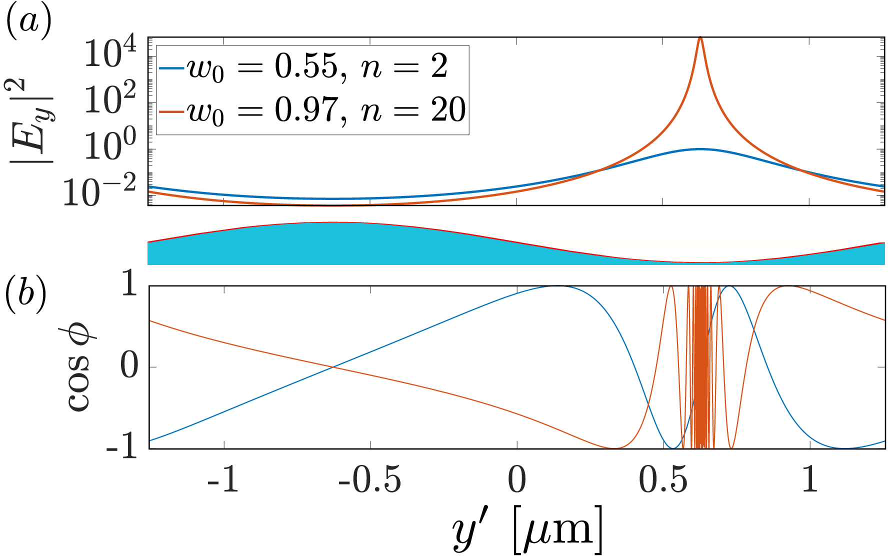
The merging of the spectrum for the singular metasurfaces is accompanied by greatly enhanced EM fields. Interestingly, these metasurfaces are able to efficiently harvest THz radiation, which then travels towards the regions where the conductivity of the graphene sheet is minimum, leading to electromagnetic fields that are increasingly squeezed towards the singular point but which never reach it due to increasingly low group velocities. In particular, our singular metasurface is able to excite a wealth of higher order modes, compared to a conventional grating. Low order modes were extensively studied in a previous work, showing a moderate field enhancement of order in amplitude.Huidobro et al. 2016 We now show how a singular metasurface () performs, compared to the weakly modulated one (). A normalized field map for the non-singular case is included in the SI for reference. The surface plasmon modes of the subwavelength grating can be easily obtained by solving the Laplace equation in the slab frame, and subsequently mapping the solution onto the grating frame via the transformation rule , where is the Jacobian matrix of the transformation. As shown in Figure 6a, these modes exhibit a field enhancement more than four orders of magnitude stronger in intensity than a non-singular grating at the graphene position. In addition, the sharp oscillations of the wavefunction near the singular point (Figure 6b) imply an enormous local density of photonic states, although the finite losses in the graphene prevent the field enhancement from rising to infinity at the singular point, and the group velocity from reaching 0. Such large EM fields can be used for spectroscopies or to enhance nonlinear phenomena by placing a nonlinear material close to the graphene. Notably, the field concentration occurs in an extended structure, so the non-linearities could be enhanced with high cross section.
2 Conclusions
In this work we have demonstrated how efficient collectors of THz light over a broad range of frequencies may be realized in graphene by patterning its Fermi level with a grating profile, while keeping very low carrier densities at a single point. By means of a suitable singular conformal map, transformation optics allowed us to exploit the hidden symmetries of this metasurface in order to unveil its continuous spectral response by considering an equivalent structure, consisting of a simple invariant slab. We have shown analytically how these gratings can strongly couple incident radiation into extremely confined surface plasmon modes, achieving absorption levels higher than of the theoretical maximum over a frequency band whose width is of the central frequency. These achievements promise to grant singular graphene metasurfaces a prominent role in the development of THz technology.
3 Methods
3.1 Graphene’s conductivity
We take the conductivity of graphene as given by the random phase approximation, which depends on frequency , chemical potential , temperature and carrier’s mobility . It can be expressed as a sum of intraband and interband contributions, , as follows Wunsch et al. 2006
| (4) | |||||
| (5) |
where and are frequency and temperature normalized to the chemical potential, respectively. The normalized damping term is , where is the carriers’ scattering time (cms-1 is the Fermi velocity).
3.2 Transformation Optics
We use transformation optics to calculate analytically the reflection and transmission coefficients of a graphene sheet with periodically modulated conductivity. We consider a p-polarized plane wave incident on the graphene grating, and transform the scalar potentials to the slab frame through the conformal transformation shown in Figure 1. The EM response of the metasurface is obtained by imposing the appropriate boundary conditions and including the radiative reaction of the graphene conductivity grating. This procedure leads to the following reflection and transmission coefficients,
| (6) | |||||
| (7) |
where and are the permittivities of air and the substrate, respectively, is the impedance of free space and is the effective conductivity of the metasurface. Here, is the conductivity of graphene in the slab frame and contains a sum over Fourier components of the transformation given by Eq. 1. Full details on this derivation and the expression for can be found in Ref. 38. Transmittance and reflectance are obtained from
| (8) | |||||
| (9) |
and absorbance is . This procedure is valid at normal incidence where all the fields are continuous through the branch points of the transformation. Out of normal incidence the waves interact with branch points and an alternative analytical approach is needed to calculate the modes of the structure.Huidobro et al. 2017
3.3 Numerical simulations
Numerical simulations were carried out with a commercial finite element method solver (Comsol Multiphysics). In our 2D simulations, the graphene layer is modelled as a current sheet with surface current . The modulated conductivity, , is obtained from Eq. 2. The modulation factor is expanded as a Fourier series for each value of considered (the first Fourier component sufficed to accurately describe the grating in the cases considered) and this spatial part multiplies as given by Eqs. 4 and 5. Transmittance and reflectance through the structure are measured in simulations of a single unit cell with periodic boundary conditions.
enerating a singular grating from an infinite slab via a conformal map; discussion on graphene’s conductivity close to the singular limit; field plots for a conventional grating; absorption profiles for grating of different periodicities and relative conductivity/chemical potential relation at their working frequencies.
References
- Bonaccorso et al. (2010) Bonaccorso, F.; Sun, Z.; Hasan, T.; Ferrari, A. C. Nature Photonics 2010, 4, 611–622.
- Vafek (2006) Vafek, O. Physical Review Letters 2006, 97, 266406.
- Hanson (2008) Hanson, G. W. Journal of Applied Physics 2008, 103, 064302.
- Jablan et al. (2009) Jablan, M.; Buljan, H.; Soljačić, M. Physical Review B 2009, 80, 245435.
- Dubinov et al. (2011) Dubinov, A. A.; Aleshkin, V. Y.; Mitin, V.; Otsuji, T.; Ryzhii, V. Journal of Phys.: Condensed Matter 2011, 23, 145302.
- Koppens et al. (2011) Koppens, F. H. L.; Chang, D. E.; García de Abajo, F. J. Nano letters 2011, 11, 3370–3377.
- Nikitin et al. (2011) Nikitin, A. Y.; Guinea, F.; García-Vidal, F. J.; Martín-Moreno, L. Physical Review B 2011, 84, 195446.
- Fei et al. (2011) Fei, Z. et al. Nano letters 2011, 11, 4701–5.
- Basov et al. (2016) Basov, D. N.; Fogler, M. M.; Garcia de Abajo, F. J. Science 2016, 354, aag1992–aag1992.
- Low et al. (2016) Low, T.; Chaves, A.; Caldwell, J. D.; Kumar, A.; Fang, N. X.; Avouris, P.; Heinz, T. F.; Guinea, F.; Martin-Moreno, L.; Koppens, F. Nature Materials 2016, 16, 182–194.
- Ni et al. (2016) Ni, G. X.; Wang, L.; Goldflam, M. D.; Wagner, M.; Fei, Z.; McLeod, A. S.; Liu, M. K.; Keilmann, F.; Özyilmaz, B.; Castro Neto, A. H.; Hone, J.; Fogler, M. M.; Basov, D. N. Nature Photonics 2016, 10, 244–247.
- Low and Avouris (2014) Low, T.; Avouris, P. ACS Nano 2014, 8, 1086–1101.
- Maier (2007) Maier, S. A. Plasmonics: Fundamentals and Applications; Springer: Boston, MA, 2007.
- Fei et al. (2012) Fei, Z.; Rodin, A. S.; Andreev, G. O.; Bao, W.; McLeod, A. S.; Wagner, M.; Zhang, L. M.; Zhao, Z.; Thiemens, M.; Dominguez, G.; Fogler, M. M.; Castro-Neto, A. H.; Lau, C. N.; Keilmann, F.; Basov, D. N. Nature 2012, 487, 82–5.
- Chen et al. (2012) Chen, J.; Badioli, M.; Alonso-González, P.; Thongrattanasiri, S.; Huth, F.; Osmond, J.; Spasenović, M.; Centeno, A.; Pesquera, A.; Godignon, P.; Elorza, A. Z.; Camara, N.; García de Abajo, F. J.; Hillenbrand, R.; Koppens, F. H. L. Nature 2012, 487, 77–81.
- Alonso-González et al. (2014) Alonso-González, P.; Nikitin, a. Y.; Golmar, F.; Centeno, A.; Pesquera, A.; Vélez, S.; Chen, J.; Navickaite, G.; Koppens, F.; Zurutuza, A.; Casanova, F.; Hueso, L. E.; Hillenbrand, R. Science (New York, N.Y.) 2014, 344, 1369–73.
- Alonso-González et al. (2016) Alonso-González, P. et al. Nature Nanotechnology 2016, 12, 1–16.
- Zhan et al. (2012) Zhan, T. R.; Zhao, F. Y.; Hu, X. H.; Liu, X. H.; Zi, J. Physical Review B 2012, 86, 165416 (2012).
- Nikitin et al. (2012) Nikitin, A. Y.; Guinea, F.; Garcia-Vidal, F. J.; Martin-Moreno, L. Physical Review B 2012, 85, 081405(R).
- Nikitin et al. (2012) Nikitin, A. Y.; Guinea, F.; Martin-Moreno, L. Applied Physics Letters 2012, 101, 151119.
- Thongrattanasiri et al. (2012) Thongrattanasiri, S.; Koppens, F. H. L.; García De Abajo, F. J. Physical Review Letters 2012, 108, 047401.
- Slipchenko et al. (2013) Slipchenko, T. M.; Nesterov, M. L.; Martin-Moreno, L.; Nikitin, a. Y. Journal of Optics 2013, 15, 114008.
- Peres et al. (2013) Peres, N. M. R.; Bludov, Y. V.; Ferreira, A.; Vasilevskiy, M. I. Journal of Physics: Condensed Matter 2013, 25, 125303.
- Stauber et al. (2014) Stauber, T.; Gómez-Santos, G.; De Abajo, F. J. Physical Review Letters 2014, 112, 077401.
- Miao et al. (2015) Miao, Z.; Wu, Q.; Li, X.; He, Q.; Ding, K.; An, Z.; Zhang, Y.; Zhou, L. Physical Review X 2015, 5, 041027.
- Zhao and Zhang (2015) Zhao, B.; Zhang, Z. M. ACS Photonics 2015, 2, 1611–1618.
- Ju et al. (2011) Ju, L.; Geng, B.; Horng, J.; Girit, C.; Martin, M.; Hao, Z.; Bechtel, H. A.; Liang, X.; Zettl, A.; Shen, Y. R.; Wang, F. Nature nanotechnology 2011, 6, 630–634.
- Tassin et al. (2013) Tassin, P.; Koschny, T.; Soukoulis, C. M. Science 2013, 341, 620–621.
- Fan et al. (2015) Fan, Y.; Shen, N.-H.; Koschny, T.; Soukoulis, C. M. ACS Photonics 2015, 2, 151–156.
- Li et al. (2015) Li, A. Y.; Kita, S.; Muñoz, P.; Reshef, O.; Vulis, D. I.; Yin, M. 2015, 9, 738–743.
- Huidobro et al. (2016) Huidobro, P. A.; Kraft, M.; Maier, S. A.; Pendry, J. B. ACS Nano 2016, 10, 5499–5506.
- Pendry et al. (2017) Pendry, J. B.; Huidobro, P. A.; Luo, Y.; Galiffi, E. Science - accepted 2017,
- Luo et al. (2010) Luo, Y.; Pendry, J. B.; Aubry, A. Nano letters 2010, 10, 4186–91.
- Ward and Pendry (1996) Ward, A. J.; Pendry, J. B. Journal of Modern Optics 1996, 43, 773 – 793.
- Pendry et al. (2006) Pendry, J. B.; Schurig, D.; Smith, D. R. Science (New York, N.Y.) 2006, 312, 1780–2.
- Leonhardt (2006) Leonhardt, U. Science 2006, 312, 1777.
- Kraft et al. (2015) Kraft, M.; Luo, Y.; Maier, S. A.; Pendry, J. B. Physical Review X 2015, 5, 031029.
- Huidobro et al. (2016) Huidobro, P. A.; Kraft, M.; Kun, R.; Maier, S. A.; Pendry, J. B. Journal of Optics 2016, 18, 44024.
- Arroyo Huidobro et al. (2017) Arroyo Huidobro, P.; Maier, S. A.; Pendry, J. B. EPJ Applied Metamaterials 2017, 4, 6.
- Savage et al. (2012) Savage, K. J.; Hawkeye, M. M.; Esteban, R.; Borisov, A. G.; Aizpurua, J.; Baumberg, J. J. Nature 2012, 491, 574–7.
- Ciracì et al. (2012) Ciracì, C.; Hill, R. T.; Mock, J. J.; Urzhumov, Y.; Fernández-Domínguez, A. I.; Maier, S. A.; Pendry, J. B.; Chilkoti, a.; Smith, D. R. Science (New York, N.Y.) 2012, 337, 1072–4.
- Lundeberg et al. (2017) Lundeberg, M.; Gao, Y.; Asgari, R.; Tan, C.; Van Duppen, B.; Autore, M.; Alonso-Gonzalez, P.; Woessner, A.; Watanabe, K.; Taniguchi, T.; Hillenbrand, R.; Hone, J.; Polini, M.; Koppens, F. H. L. Science 2017, 2735, 1–10.
- Tonouchi (2007) Tonouchi, M. Nature Photonics 2007, 1, 97–105.
- Wunsch et al. (2006) Wunsch, B.; Stauber, T.; Sols, F.; Guinea, F. New Journal of Physics 2006, 8, 318–318.
- Huidobro et al. (2017) Huidobro, P. A.; Chang, Y. H.; Kraft, M.; Pendry, J. B. Physical Review B 2017, 95, 1–8.