A six-apertures discrete beam combiners for J-band interferometry
Abstract
The astronomical J-band (1.25 micrometres) is a relatively untapped wave-band in long-baseline infrared interferometry. It allows access to the photosphere in giant and super-giant stars relatively free from opacities of molecular bands. The J-band can potentially be used for imaging spots in the 1350 nm ionised iron line on slowly rotating magnetically-active stars through spectro-interferometry. In addition, the access to the 1080 nanometres He I line may probe outflows and funnel-flows in T-Tauri stars and allow the study of the star-disk interaction.
We present the progress in the development of a six-inputs, J-band interferometric beam combiner based on the discrete beam combiner (DBC) concept. DBCs are periodic arrays of evanescent coupled waveguides which can be used to retrieve simultaneously the complex visibility of every baseline from a multi-aperture interferometer. Existing, planned or future interferometric facilities combine or will combine six or more telescopes at the time, thus increasing the snapshot uv coverage from the interferometric measurements. A better uv coverage will consequently enhance the accuracy of the image reconstruction. DBCs are part of the wider project “Integrated astrophotonics” that aims to validates photonic technologies for utilisation in astronomy.
Before manufacturing the component we performed extensive numerical simulations with a coupled modes model of the DBC to identify the best input configuration and array length. The 41 waveguides were arranged on a zig-zag array that allows a simple optical setup for dispersing the light at the output of the waveguides.
The component we are currently developing is manufactured in borosilicate glass using the technique of multi-pass ultrafast laser inscription (ULI), using a mode-locked Yb:KYW laser at the wavelength of 1030 nm, pulse duration of 300 fs and repetition rate of 1 MHz. After annealing, the written components showed a propagation loss less than 0.3 dB/cm and a negligible birefringence at a wavelength of 1310 nm, which makes the components suitable for un-polarized light operation. A single mode fiber-to-component insertion loss of 0.9 dB was measured. Work is currently in progress to characterize the components in spectro-interferometric mode with white light covering the J-band spectrum.
keywords
Stellar Interferometry, Long–Baseline Interferometry, Astrophotonics, Beam Combiners, Fibre Optics.E.P: E–mail:epedretti@aip.de
1 Introduction
Long–baseline infrared interferometry has undoubtly benefited from the development of photonics components for the telecommunication industry. The use of integrated optics components in stellar interferometry happened before the term “Astrophotonics” was invented to describe photonic components applied to astronomical instrumentation. Although multi–mode pupil–plane, coaxial beam combiners in bulk optics were used in the early interferometers[1] the issues of complexity, calibration and stability prevented the use of bulk–optics beam combiners for interferometers composed of more than two telescopes. The difficulty of combining more than two telescopes and the lack of sensitive detectors delayed significantly the imaging of complex object with long–baseline stellar interferometry.
With the advent of fibre optics beam combiners[2, 3, 4, 5], that used fibre couplers instead of beam splitters and beam combiners, the era of precision interferometry was born. Fibre couplers allowed the acquisition of high accuracy squared visibilities on a single telescope baseline and the measurement of accurate stellar diameters. Further advance came with the development of planar integrated optics components, in particular the IONIC[5, 6, 7]. The IONIC–3T was tested and deployed[8] at the infrared optical telescope array (IOTA)[9, 10, 11]. Together with a sentitive infrared camera[12], the first operational 3–telescope fringe tracker[13] and a low resolution spectrograph[14, 15] IOTA was the first long–baseline interferometer to produce science results using “Astrophotonics” components[16, 17, 18, 19, 20, 21, 22, 23].
The limitations of planar integrated optics became evident when combining four or more telescopes[24, 25] due to increase in complexity when using couplers for beam combination. The idea of utilising three–dimensional structures for beam combination gained traction when ultrafast laser inscription (ULI) for astronomy became a reality[26, 27, 28, 29]. The possibility of avoiding the crossing over of couplers waveguides simplified the complexity of the beam combiners and reduced the optical crosstalk in the component. Unfortunately the low confinement of light in waveguides, intrinsic in ULI technology low–contrast waveguides, caused losses of light and low throughput from the first prototypes[30].

The discrete beam combiner (DBC) concept overcomes some of the limitations of low–throughput beam combiners written with ULI technology. The theory of the DBC is extensively described in several publications[31, 28, 32, 33, 34, 35, 36]. Briefly in the DBC concept a two-dimensional lattice of parallel waveguides is written to a glass substrate using ULI. Evanescent coupling among the waveguides allows the interferometric mixing of the input fields at the outputs of the lattice, from which the complex visibilities can be retrieved from a measurement of the power at each output site. Figure 1 shows an example for a 4–telescope zig-zag DBC geometry of coupled waveguide lattice. A DBC can measure the mutual coherence of the input field or the “complex visibility” without the necessity of scanning the optical path that was necessary in coaxial beam combiner or the early integrated optics beam combiners like IONIC–3T. This is not dissimilar from a “classic” image–plane beam combiner where the intensity in the focal plane is the linear combination from the input of all the telescopes beselines. In a an image plane beam combiner the telescope baselines are spatially encoded in the interference fringe patterns recorded by a camera and the complex visibilities for each baselines can be extracted by a simple Fourier transform or by deriving the pixel to visibility matrix[37] (P2VM). In the DBC the intensity of the output waveguides can also be transformed to a complex visibilities by multiplying the outputs by the P2VM that is obtained by inverting the visibility to pixel matrix[37] (V2PM). Explanation of how to obtain the V2PM for an image–plane beam combiner[37], a planar integrated optics beam combiner[38] and a DBC[33] are given in the references.
We have manufactured a six–telescope DBC working in the astronomical J band (1.25 ) using borosilicate glass and ultra–fast laser inscription. This is to our knowledge the first integrated optics beam combiner working in the J band ever manufactured. The 1.25 astronomical J-band is relatively untapped waveband for long baseline infrared interferometry. The J band allows access to the photosphere of giant and supergiant stars relatively free from opacities of molecular bands allowing the characterisation of large–scale convection cells on giant and supergiant stars[39]. It will enable high accuracy diameter measurement with higher resolution than the commonly used astronomical H-band. Iron (Fe ii): 1183nm 1291nm in stellar spots. The He 1083 nm line to probe inflow and outflow in T–Tauri stars[40, 41].
2 Six telescope discrete beam combiner for the J band

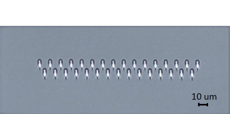
The 6-telescope combiner was written in boro–alumino–silicate glass with the technique of multi–pass ultra–fast laser inscription, using a mode-locked Yb:KYW laser at the wavelength of 1030 nm, pulse duration of 300 fs and repetition rate of 1 MHz. In order to get single-mode waveguides with low losses at the wavelength of interest, we used the multi–scan technique, consisting in writing a waveguide multiple times, to increase the refractive index change.
To find the optimal writing parameters, we fabricated waveguides with different powers, speeds and number of scans, and characterised them with a 1310 nm laser diode. To study the planar coupling, we fabricated a set of planar arrays of N = 31 waveguides with different interaction lengths (0.5 cm and 1.5 cm) and distances (from 10 m to 17 m, with a spacing of 1 m). The arrays were then characterised by injecting in the central waveguide horizontally or vertically polarized light with a wavelength of 1310 nm. The outputs, collected with a Vidicon camera, were compared with numerical simulations in order to estimate the coupling coefficient.
After the study of the planar coupling, new devices were fabricated to investigate the dependence of the diagonal coupling on the angle between the waveguides. Indeed, a difference in the coupling strength for waveguides in and out of plane may arise from a non perfect circular mode profile[42]. The geometry of the circuit is shown in Figure 2: two planes of waveguides with the same coupling distance are put close to each other in order to have a diagonal interaction between them (all distances between neighbouring waveguides are equal). While the central waveguide in the lower plane starts at the beginning of the sample and can be therefore coupled with light for the characterization of the device, the other ones start in the sample, so they can guide light only by power exchange with the central waveguide.
After fabrication, the waveguides were subjected to an annealing process, which reduces their birefringence by releasing laser induced stress. After annealing, (see Figure 2) the written components showed a propagation loss less than 0.3 dB/cm and a negligible birefringence at a wavelength of 1310 nm, which makes the components suitable for un-polarized light operation. A single mode fibre-to-component insertion loss of 0.9 dB was measured. Work is currently in progress to characterize the components in spectro-interferometric mode with white light covering the J-band spectrum. Many devices were fabricated, each one with a specific interwaveguide distance, ranging from 12 m to 18 m, and an array length from 4 mm to 16 mm depending on the coupling coefficient estimated in the previous measurements (in order to match the device with the design). The relative values of the diagonal and horizontal coupling coefficient was estimated by fitting the output distribution with a two-parameter coupled modes model.
After this calibration, we fabricated a 6-telescope DBC featuring 41 waveguides. In particular, we adopted the scheme in Figure 4 (bottom), which was selected as the best among all possible input configurations. Waveguides 4, 10, 16, 19, 31 and 38 start from the beginning of the sample, therefore can be coupled with light, while the other waveguides start in the glass. We employed a inter–waveguide separation of 16 m and an array length length of 4 cm, which corresponds to the optimal design.

The interferometric test of the manufactured components usually requires a lengthy calibration of the V2PM for all 15 input combinations. To speed up the procedure, we set-up an automated test facility that permits to characterise single waveguides and beam combiners of 6–telescope complexity without the need of manual steering of the beams in order to find the input sites. The combiners will then be tested with a tunable laser ranging from 1250 to 1350 nm in order to characterise the beam combiner across the whole bandwidth.
3 Interferometry testbench
The beam combiners were characterised on our automated testbench at the innoFSPEC in Potsdam. A picture of the testbench is shown in Figure 3. We used a Michelson interferometer capable of injecting two beams in the component through a direct and a delayed path. The delayed path uses a USB–controlled delay line connected to a computer to change the optical path difference (OPD). The chromatic response of the component can be characterised using two separate tunable laser sources: one at 1.3 for the J–band and one at 1.5 for the H–band.

The beam from the tunable source is split in two using a beam splitter and directed to two kinematic mounts. The mounts can be steered using stepper motors controlled by a computer through a serial link and are able to address the different inputs of the component. Images are recorded by a fast infrared camera connected to the same computer controlling the stepper motors and the delay line. The camera is connected to the computer using a camera-link interface wired to a frame-grabber card. The a map of the inputs of the components are shown on Figure 4 top.


The inputs of the component are automatically found by performing a raster scan on the inputs using the stepper motors and measuring the integrated intensity from the outputs of the DBC. A XY map of the intensity is then built and the outputs found. We use the open–source library OpenCV to identify the inputs position and derive the XY coordinates[43]. Once we have the positions of the inputs for the two beams we can build the V2PM matrix of the component as described in[33].
One beam only is injected and all the outputs recorded by the camera and the images saved as FITS files. The procedure is repeated for all six beams. This gives us a measurement of the photometry of the inputs. Two beams are then injected and a USB–controlled delay line scanned with steps that are 1/10 of the laser wavelength in use. An image of the camera is acquired for each step and recorded as a FITS image cube of the output of the component. The pixels corresponding to the output channels of the combiner are extracted and the photometry, obtained from single beams injection, subtracted from each channel separately.
Figure 5 shows a time series from the channels extracted from output 16 of the waveguide for all possible combinations of two input beams (or baselines, on a real instrument). We calculate a FFT for each time series. The parameters extracted with the FFT are used as initial parameters for a sine plus cosine quadratures model. We extract the real and imaginary part of the interfering fields by applying a least–square fit to the fringe data using Equation 1:
| (1) |
The extracted parameters a and b are the real and imaginary part of the interference fringe. These values are placed in the V2PM matrix together with the photometry as described in [33]. After the V2PM matrix is filled up it can be inverted to give the pixel to visibility matrix (P2VM) that relates the output recorded from the camera to the complex visibilities for all baselines and photometry for all telescopes in the array.
4 Conclusions
We have presented the progress in the development of a six-inputs, J-band interferometric beam combiner based on the discrete beam combiner (DBC) concept.
Before manufacturing the component we performed extensive numerical simulations with a coupled modes model of the DBC to identify the best input configuration and array length. The 41 waveguides were arranged on a zig-zag array that allows a simple optical setup for dispersing the light at the output of the waveguides.
The component we are currently developing is manufactured in borosilicate glass using the technique of multi-pass ultrafast laser inscription (ULI), using a mode-locked Yb:KYW laser at the wavelength of 1030 nm, pulse duration of 300 fs and repetition rate of 1 MHz. After annealing, the written components showed a propagation loss less than 0.3 dB/cm and a negligible birefringence at a wavelength of 1310 nm, which makes the components suitable for un-polarized light operation. A single mode fiber-to-component insertion loss of 0.9 dB was measured. Work is currently in progress to characterize the components in spectro-interferometric mode with white light covering the J-band spectrum.
Acknowledgements.
The author gratefully acknowledge the financial support from the Federal Ministry of Education and Research (BMBF), grant number 03Z22AN11. This research has made use of NASA’s Astrophysics Data System Bibliographic Services. This research made use of the IPython package [44]; matplotlib, a Python library for publication quality graphics [45].References
- [1] A. Labeyrie, “Interference fringes obtained on VEGA with two optical telescopes,” ApJ 196, pp. L71–L75, Mar. 1975.
- [2] V. Coudé du-Foresto and S. T. Ridgway, “Fluor - a Stellar Interferometer Using Single-Mode Fibers,” in European Southern Observatory Astrophysics Symposia, J. M. Beckers and F. Merkle, eds., European Southern Observatory Astrophysics Symposia 39, pp. 731–+, Mar. 1992.
- [3] V. Coudé du Foresto, G. Perrin, J.-M. Mariotti, M. Lacasse, and W. Traub, The FLUOR/IOTA fiber stellar interferometer, pp. 115–125. Integrated Optics for Astronomical Interferometry, 1997.
- [4] V. Coude du Foresto, P. J. Borde, A. Merand, C. Baudouin, A. Remond, G. S. Perrin, S. T. Ridgway, T. A. ten Brummelaar, and H. A. McAlister, “FLUOR fibered beam combiner at the CHARA array,” in Society of Photo-Optical Instrumentation Engineers (SPIE) Conference Series, W. A. Traub, ed., Society of Photo-Optical Instrumentation Engineers (SPIE) Conference Series 4838, pp. 280–285, Feb. 2003.
- [5] K. Rousselet-Perraut, E. Stadler, P. Feautrier, E. Le Coarer, P. Petmezakis, P. Haguenauer, P. Kern, F. Malbet, J.-P. Berger, I. Schanen-Duport, P. Benech, and L. Delage, “The Integrated Optics Near-infrared Interferometric Camera (IONIC),” in Working on the Fringe: Optical and IR Interferometry from Ground and Space, S. Unwin and R. Stachnik, eds., Astronomical Society of the Pacific Conference Series 194, p. 344, 1999.
- [6] K. Rousselet-Perraut, P. Haguenauer, P. Petmezakis, J.-P. Berger, D. Mourard, S. D. Ragland, G. Huss, F. Reynaud, E. Le Coarer, P. Y. Kern, and F. Malbet, “Qualification of IONIC (integrated optics near-infrared interferometric camera),” in Interferometry in Optical Astronomy, P. Léna and A. Quirrenbach, eds., Proc. SPIE 4006, pp. 1042–1051, July 2000.
- [7] P. Haguenauer, Qualification de IONIC, instrument de recombinaison interferometrique base sur des composants d’optique planaire dedie a l’astronomie. PhD thesis, PhD Thesis, Universite de Grenoble, 2001. 222 p., 2001.
- [8] J.-P. Berger, P. Haguenauer, P. Y. Kern, K. Rousselet-Perraut, F. Malbet, S. Gluck, L. Lagny, I. Schanen-Duport, E. Laurent, A. Delboulbe, E. Tatulli, W. A. Traub, N. Carleton, R. Millan-Gabet, and J. D. Monnier, “An integrated-optics 3-way beam combiner for IOTA,” in Society of Photo-Optical Instrumentation Engineers (SPIE) Conference Series, W. A. Traub, ed., Society of Photo-Optical Instrumentation Engineers (SPIE) Conference Series 4838, pp. 1099–1106, Feb. 2003.
- [9] N. P. Carleton, “The IOTA project.,” in European Southern Observatory Conference and Workshop Proceedings, F. Merkle, ed., European Southern Observatory Conference and Workshop Proceedings 29, pp. 939–946, 1988.
- [10] W. A. Traub, M. G. Lacasse, and N. P. Carleton, “Spectral dispersion and fringe detection in IOTA,” in Amplitude and intensity spatial interferometry; Proceedings of the Meeting, Tucson, AZ, Feb. 14-16, 1990 (A91-30676 12-89). Bellingham, WA, Society of Photo-Optical Instrumentation Engineers, 1990, p. 145-152. Research supported by NASA and Smithsonian Institution., pp. 145–152, Aug. 1990.
- [11] H. M. Dyck, J. A. Benson, N. P. Carleton, C. Coldwell, M. G. Lacasse, P. Nisenson, A. Panasyuk, C. Papaliolios, M. R. Pearlman, R. D. Reasenberg, W. A. Traub, A. Xu, C. R. Predmore, F. P. Schloerb, and D. M. Gibson, “First 2.2 micrometer results from the IOTA interferometer,” AJ 109, pp. 378–382, Jan. 1995.
- [12] E. Pedretti, R. Millan-Gabet, J. D. Monnier, W. A. Traub, N. P. Carleton, J.-P. Berger, M. G. Lacasse, F. P. Schloerb, and M. K. Brewer, “The PICNIC Interferometry Camera at IOTA,” PASP 116, pp. 377–389, Apr. 2004.
- [13] E. Pedretti, W. A. Traub, J. D. Monnier, R. Millan-Gabet, N. P. Carleton, F. P. Schloerb, M. K. Brewer, J.-P. Berger, M. G. Lacasse, and S. Ragland, “Robust determination of optical path difference: fringe tracking at the Infrared Optical Telescope Array interferometer,” Appl. Opt. 44, pp. 5173–5179, Sept. 2005.
- [14] S. Ragland, W. A. Traub, R. Millan-Gabet, N. P. Carleton, and E. Pedretti, “A Low-resolution spectrograph for the IOTA interferometer,” in Interferometry for Optical Astronomy II. Edited by Wesley A. Traub . Proceedings of the SPIE, Volume 4838, pp. 1225-1233 (2003)., W. A. Traub, ed., Presented at the Society of Photo-Optical Instrumentation Engineers (SPIE) Conference 4838, pp. 1225–1233, Feb. 2003.
- [15] E. Pedretti, W. A. Traub, J. D. Monnier, P. A. Schuller, S. Ragland, J. Berger, R. Millan-Gabet, G. Wallace, M. Burke, M. G. Lacasse, N. D. Thureau, and N. Carleton, “Last technology and results from the IOTA interferometer,” in Optical and Infrared Interferometry, Proc. SPIE 7013, p. 70132V, July 2008.
- [16] J. D. Monnier, W. A. Traub, F. P. Schloerb, R. Millan-Gabet, J.-P. Berger, E. Pedretti, N. P. Carleton, S. Kraus, M. G. Lacasse, M. Brewer, S. Ragland, A. Ahearn, C. Coldwell, P. Haguenauer, P. Kern, P. Labeye, L. Lagny, F. Malbet, D. Malin, P. Maymounkov, S. Morel, C. Papaliolios, K. Perraut, M. Pearlman, I. L. Porro, I. Schanen, K. Souccar, G. Torres, and G. Wallace, “First Results with the IOTA3 Imaging Interferometer: The Spectroscopic Binaries Virginis and WR 140,” ApJ 602, pp. L57–L60, Feb. 2004.
- [17] R. Millan-Gabet, J. D. Monnier, J.-P. Berger, W. A. Traub, F. P. Schloerb, E. Pedretti, M. Benisty, N. P. Carleton, P. Haguenauer, P. Kern, P. Labeye, M. G. Lacasse, F. Malbet, K. Perraut, M. Pearlman, and N. Thureau, “Bright Localized Near-Infrared Emission at 1-4 AU in the AB Aurigae Disk Revealed by IOTA Closure Phases,” ApJ 645, pp. L77–L80, July 2006.
- [18] J. D. Monnier, J.-P. Berger, R. Millan-Gabet, W. A. Traub, F. P. Schloerb, E. Pedretti, M. Benisty, N. P. Carleton, P. Haguenauer, P. Kern, P. Labeye, M. G. Lacasse, F. Malbet, K. Perraut, M. Pearlman, and M. Zhao, “Few Skewed Disks Found in First Closure-Phase Survey of Herbig Ae/Be Stars,” ApJ 647, pp. 444–463, Aug. 2006.
- [19] J. D. Monnier, R. K. Barry, W. A. Traub, B. F. Lane, R. L. Akeson, S. Ragland, P. A. Schuller, H. Le Coroller, J.-P. Berger, R. Millan-Gabet, E. Pedretti, F. P. Schloerb, C. Koresko, N. P. Carleton, M. G. Lacasse, P. Kern, F. Malbet, K. Perraut, M. J. Kuchner, and M. W. Muterspaugh, “No Expanding Fireball: Resolving the Recurrent Nova RS Ophiuchi with Infrared Interferometry,” ApJ 647, pp. L127–L130, Aug. 2006.
- [20] S. Ragland, W. A. Traub, J.-P. Berger, W. C. Danchi, J. D. Monnier, L. A. Willson, N. P. Carleton, M. G. Lacasse, R. Millan-Gabet, E. Pedretti, F. P. Schloerb, W. D. Cotton, C. H. Townes, M. Brewer, P. Haguenauer, P. Kern, P. Labeye, F. Malbet, D. Malin, M. Pearlman, K. Perraut, K. Souccar, and G. Wallace, “First Surface-resolved Results with the Infrared Optical Telescope Array Imaging Interferometer: Detection of Asymmetries in Asymptotic Giant Branch Stars,” ApJ 652, pp. 650–660, Nov. 2006.
- [21] M. Zhao, J. D. Monnier, G. Torres, A. F. Boden, A. Claret, R. Millan-Gabet, E. Pedretti, J.-P. Berger, W. A. Traub, F. P. Schloerb, N. P. Carleton, P. Kern, M. G. Lacasse, F. Malbet, and K. Perraut, “Physical Orbit for Virginis and a Test of Stellar Evolution Models,” ApJ 659, pp. 626–641, Apr. 2007.
- [22] E. Pedretti, J. D. Monnier, S. Lacour, W. A. Traub, W. C. Danchi, P. G. Tuthill, N. D. Thureau, R. Millan-Gabet, J.-P. Berger, M. G. Lacasse, P. A. Schuller, F. P. Schloerb, and N. P. Carleton, “Detection of non-radial pulsation and faint companion in the symbiotic star CH Cyg,” MNRAS 397, pp. 325–334, July 2009.
- [23] N. D. Thureau, J. D. Monnier, W. A. Traub, R. Millan-Gabet, E. Pedretti, J.-P. Berger, M. R. Garcia, F. P. Schloerb, and A.-K. Tannirkulam, “Imaging the asymmetric dust shell around CI Cam with long baseline optical interferometry,” MNRAS 398, pp. 1309–1316, Sept. 2009.
- [24] M. Benisty, J.-P. Berger, L. Jocou, F. Malbet, K. Perraut, P. Labeye, and P. Kern, “The VSI/VITRUV combiner: a phase-shifted four-beam integrated optics combiner,” in Society of Photo-Optical Instrumentation Engineers (SPIE) Conference Series, Proc. SPIE 6268, p. 62682D, June 2006.
- [25] M. Benisty, J. Berger, L. Jocou, P. Labeye, F. Malbet, K. Perraut, and P. Kern, “An integrated optics beam combiner for the second generation VLTI instruments,” A&A 498, pp. 601–613, May 2009.
- [26] R. R. Thomson, A. K. Kar, and J. Allington-Smith, “Ultrafast laser inscription: an enabling technology for astrophotonics,” Optics Express 17, pp. 1963–1969, Feb. 2009.
- [27] A. Ródenas, G. Martin, B. Arezki, N. Psaila, G. Jose, A. Jha, L. Labadie, P. Kern, A. Kar, and R. Thomson, “Three-dimensional mid-infrared photonic circuits in chalcogenide glass,” Opt. Lett. 37, p. 392, Feb. 2012.
- [28] S. Minardi, F. Dreisow, M. Gräfe, S. Nolte, and T. Pertsch, “Three-dimensional photonic component for multichannel coherence measurements,” Opt. Lett. 37, pp. 3030–3032, 2012.
- [29] N. Jovanovic, P. G. Tuthill, B. Norris, S. Gross, P. Stewart, N. Charles, S. Lacour, M. Ams, J. S. Lawrence, A. Lehmann, C. Niel, J. G. Robertson, G. D. Marshall, M. Ireland, A. Fuerbach, and M. J. Withford, “Starlight demonstration of the Dragonfly instrument: an integrated photonic pupil-remapping interferometer for high-contrast imaging,” Month. Not. R. Astron. Soc. 427, pp. 806–815, Nov. 2012.
- [30] J. Tepper, L. Labadie, R. Diener, S. Minardi, J.-U. Pott, R. Thomson, and S. Nolte, “Integrated optics prototype beam combiner for long baseline interferometry in the L and M bands,” A&A 602, p. A66, June 2017.
- [31] S. Minardi and T. Pertsch, “Interferometric beam combination with discrete optics,” Optics Letters 35, p. 3009, Aug. 2010.
- [32] S. Minardi, “Photonic lattices for astronomical interferometry,” MNRAS 422, pp. 2656–2660, May 2012.
- [33] A. Saviauk, S. Minardi, F. Dreisow, S. Nolte, and T. Pertsch, “3D-integrated optics component for astronomical spectro-interferometry,” Appl. Opt. 52, p. 4556, July 2013.
- [34] S. Minardi, A. Saviauk, F. Dreisow, S. Nolte, and T. Pertsch, “3D-integrated beam combiner for optical spectro-interferometry,” in Optical and Infrared Interferometry IV, Proc. SPIE 9146, p. 91461D, July 2014.
- [35] R. Errmann and S. Minardi, “6- and 8-telescope discrete beam combiners,” in Optical and Infrared Interferometry and Imaging V, Proc. SPIE 9907, p. 990733, Aug. 2016.
- [36] R. Diener, J. Tepper, L. Labadie, T. Pertsch, S. Nolte, and S. Minardi, “Towards 3D-photonic, multi-telescope beam combiners for mid-infrared astrointerferometry,” Optics Express 25, pp. 19262–19274, Aug. 2017.
- [37] E. Tatulli, F. Millour, A. Chelli, G. Duvert, B. Acke, O. Hernandez Utrera, K.-H. Hofmann, S. Kraus, F. Malbet, P. Mège, R. G. Petrov, M. Vannier, G. Zins, P. Antonelli, U. Beckmann, Y. Bresson, M. Dugué, S. Gennari, L. Glück, P. Kern, S. Lagarde, E. Le Coarer, F. Lisi, K. Perraut, P. Puget, F. Rantakyrö, S. Robbe-Dubois, A. Roussel, G. Weigelt, M. Accardo, K. Agabi, E. Altariba, B. Arezki, E. Aristidi, C. Baffa, J. Behrend, T. Blöcker, S. Bonhomme, S. Busoni, F. Cassaing, J.-M. Clausse, J. Colin, C. Connot, A. Delboulbé, A. Domiciano de Souza, T. Driebe, P. Feautrier, D. Ferruzzi, T. Forveille, E. Fossat, R. Foy, D. Fraix-Burnet, A. Gallardo, E. Giani, C. Gil, A. Glentzlin, M. Heiden, M. Heininger, D. Kamm, M. Kiekebusch, D. Le Contel, J.-M. Le Contel, T. Lesourd, B. Lopez, M. Lopez, Y. Magnard, A. Marconi, G. Mars, G. Martinot-Lagarde, P. Mathias, J.-L. Monin, D. Mouillet, D. Mourard, E. Nussbaum, K. Ohnaka, J. Pacheco, C. Perrier, Y. Rabbia, S. Rebattu, F. Reynaud, A. Richichi, A. Robini, M. Sacchettini, D. Schertl, M. Schöller, W. Solscheid, A. Spang, P. Stee, P. Stefanini, M. Tallon, I. Tallon-Bosc, D. Tasso, L. Testi, F. Vakili, O. von der Lühe, J.-C. Valtier, and N. Ventura, “Interferometric data reduction with AMBER/VLTI. Principle, estimators, and illustration,” A&A 464, pp. 29–42, Mar. 2007.
- [38] S. Lacour, L. Jocou, T. Moulin, P. R. Labeye, M. Benisty, J.-P. Berger, A. Delboulbé, X. Haubois, E. Herwats, P. Y. Kern, F. Malbet, K. Rousselet-Perraut, and G. Perrin, “Characterization of integrated optics components for the second generation of VLTI instruments,” in Optical and Infrared Interferometry, Proc. SPIE 7013, p. 701316, July 2008.
- [39] C. Paladini, F. Baron, A. Jorissen, J.-B. Le Bouquin, B. Freytag, S. van Eck, M. Wittkowski, J. Hron, A. Chiavassa, J.-P. Berger, C. Siopis, A. Mayer, G. Sadowski, K. Kravchenko, S. Shetye, F. Kerschbaum, J. Kluska, and S. Ramstedt, “Large granulation cells on the surface of the giant star 1 Gruis,” Nature 553, pp. 310–312, Jan. 2018.
- [40] W. Fischer, J. Kwan, S. Edwards, and L. Hillenbrand, “Redshifted Absorption at He I 10830 as a Probe of the Accretion Geometry of T Tauri Stars,” ApJ 687, pp. 1117–1144, Nov. 2008.
- [41] R. Kurosawa, M. M. Romanova, and T. J. Harries, “Multidimensional models of hydrogen and helium emission line profiles for classical T Tauri stars: method, tests and examples,” MNRAS 416, pp. 2623–2639, Oct. 2011.
- [42] R. Osellame, S. Taccheo, M. Marangoni, R. Ramponi, P. Laporta, D. Polli, S. de Silvestri, and G. Cerullo, “Femtosecond writing of active optical waveguides with astigmatically shaped beams,” Journal of the Optical Society of America B Optical Physics 20, pp. 1559–1567, July 2003.
- [43] G. Bradski, “The OpenCV Library,” Dr. Dobb’s Journal of Software Tools , 2000.
- [44] F. Pérez and B. E. Granger, “IPython: a system for interactive scientific computing,” Computing in Science and Engineering 9, pp. 21–29, May 2007.
- [45] J. D. Hunter, “Matplotlib: A 2d graphics environment,” Computing In Science & Engineering 9(3), pp. 90–95, 2007.