Three Efficient, Low-Complexity Algorithms for Automatic Color TrappingThanks: This research was supported by the Hewlett-Packard Company.
Abstract
Color separations (most often cyan, magenta, yellow, and black) are commonly used in printing to reproduce multi-color images. For mechanical reasons, these color separations are generally not perfectly aligned with respect to each other when they are rendered by their respective imaging stations. This phenomenon, called color plane misregistration, causes gap and halo artifacts in the printed image. Color trapping is an image processing technique that aims to reduce these artifacts by modifying the susceptible edge boundaries to create small, unnoticeable overlaps between the color planes (either at the page description language level or the rasterized image level). In this paper, we propose three low-complexity algorithms for automatic color trapping at the rasterized image level which hide the effects of small color plane mis-registrations. Our proposed algorithms are designed for software or embedded firmware implementation. The trapping method they follow is based on a hardware-friendly technique proposed by J. Trask (JTHBCT03) which is too computationally expensive for software or firmware implementation. The first two algorithms are based on the use of look-up tables (LUTs). The first LUT-based algorithm corrects all registration errors of one pixel in extent and reduces several cases of misregistration errors of two pixels in extent using only Kbytes of storage space. This algorithm is particularly attractive for implementation in the embedded firmware of low-cost formatter-based printers. The second LUT-based algorithm corrects all types of misregistration errors of up to two pixels in extent using Mbytes of storage space. This algorithm is more suitable for software implementation on host-based printers. The third algorithm is a hybrid one that combines look-up tables and feature extraction to minimize the storage requirements ( Kbytes) while still correcting all misregistration errors of up to two pixels in extent. This algorithm is suitable for both embedded firmware implementation on low-cost formatter-based printers and software implementation on host-based printers. All three of our proposed algorithms run, in average, more than three times faster than a software implementation of JTHBCT03.
Index Terms:
Color trapping, color plane misregistration, look-up tables.I Introduction
The color laser printer market is currently dominated by two laser electrophotographic (EP) printing architectures: multi-pass and in-line. Multi-pass color printers (Fig. 1) operate by sequentially overlaying single color image planes on an optical photoconductor (OPC) drum and subsequently transferring all image planes in a single step onto the paper. The surface of the OPC drum thus acts as an intermediate transfer material on which all the different colorants (i.e., toner powders) are applied. This is done by first charging the OPC drum surface using a charging roller and putting a toner unit into position. A laser beam is then used to selectively remove the charge on the OPC drum surface according to the image for that color plane. The locations where the charges have been removed attract the toner particles to the OPC drum surface. This process is repeated four times - one time each for cyan (), magenta (), yellow (), and black (). The OPC drum is subsequently put in contact with the paper to transfer the colored particles onto it, and a cleaning blade is applied to the OPC drum. The paper then goes through a fuser, which is used to bond all four colors of toner to the paper by exerting heat and pressure. Since the image planes are created in separate mechanical operations within the printing process, it is very difficult and costly to perfectly align them.
For in-line printers (Fig. 2), there are four separate imaging stations, each with its own OPC drum and toner unit (, , , or ). The toner is either applied directly on the paper itself while it is transported by a transfer belt, or the transfer belt is used as an intermediate transfer material. All four toner colors are fused onto the paper in a single final step. Misregistration occurs as a result of misalignments between the paper (or intermediate transfer material) and the imaging stations.
When printed at dpi resolution, misalignments of a magnitude as small as one pixel can form visible artifacts in the printed image. A mechanical accuracy of more than inch in the image plane position is required to prevent visible artifacts [1]. Unfortunately, desktop, workgroup, and office printers do not possess this level of mechanical accuracy. This results in gap and/or halo artifacts near the edges of objects in each color plane. Examples of a white gap artifact and a yellow halo artifact are shown in Figs. 3 and 4, respectively.


Color trapping is a workaround to this problem that consists of moving the edge boundaries of the lighter colorants underneath the edge boundaries of the darker colorants. While the resulting change in the image is almost imperceptible to the human eye, this prevents the appearance of gap and halo artifacts caused by small color plane mis-registrations. Color trapping is commonly used in high-quality commercial printing with an offset press. Typically, this is done manually by a trained graphic artist using a professional page layout application. Manual color trapping entails examining each page displayed on a computer screen to predict where the registration errors are likely to occur, and creating traps to prevent the errors. Until recently, the underlying professional printing applications were quite expensive. More recently, a class of low-cost desktop publishing software (e.g., Adobe InDesign, Quark XPress) has emerged that allows users with a personal computer to create high quality documents. Still, this manual procedure is tedious and requires advanced skills, which makes it unattractive for low-end publishing by relatively casual users. A fully automatic solution is thus preferred.
There is a very limited body of literature on automatic color trapping. As far as we know, this issue has not previously been discussed in the scholarly engineering literature. Aside from nondescriptive commercial product advertisements, the only published work on the subject appears to be in the form of patents. We give a high-level summary of current automatic color trapping approaches in the next section.
Automatic color trapping can be performed in hardware, in software, or in firmware. Hardware-based color trapping is done by including specific hardware components (e.g., printer application specific integrated circuits (ASICs)) to perform specific tasks within the printer. Once a hardware circuit has been designed, it is difficult to alter. So while hardware-based trapping is fast, it is inflexible and costly. Software-based trapping is performed by the host computer, either through a stand-alone application such as Adobe InDesign, or through the printer driver. Software-based trapping is flexible, easy to tailor for different trapping needs, and also cost effective. Software friendly algorithms that have low memory and computational requirements can also be implemented directly in firmware to run on the microprocessor of a formatter-based printer.
Due to architectural differences, hardware-based algorithms are typically not suitable for software implementation and vice versa. In this paper, we present three efficient automatic color trapping algorithms for software or firmware implementation. Our approaches build on a hardware-friendly algorithm developed by J. Trask [1] in 2003 (JTHBCT03). Overall, the trapped images they produce are very similar to those generated by JTHBCT03. However, all three proposed algorithms are computationally simpler than JTHBCT03. They are thus more amenable to software implementation. In addition, two of them have very low memory requirement, which makes them suitable for firmware implementation.
JTHBCT03 uses a sliding window to determine how to process each pixel of a given rasterized image. One approach that we use to reduce the complexity is to employ look-up tables (LUTs). In particular, in all three algorithms, the trapping parameters, which determine how the color of the center pixel of the window is to be modified, are stored in a LUT rather than being computed every time. In our first algorithm, an approximation of JTHBCT03 is obtained by considering a smaller ( pixel) window. The pixel configuration is used to obtain the index of a LUT in which is stored the corresponding action that should be taken: either trap as an edge pixel or do not trap. This algorithm reduces several cases of misregistration errors up to two pixels in extent using only Kbytes of storage space. It is particularly attractive for implementation on the firmware of low-cost formatter-based printers.
In our second algorithm, a window is considered and a series of LUTs are built to replicate JTHBCT03’s decision: either trap as an edge pixel, trap as a neighboring edge pixel, or do not trap. This algorithm corrects all types of misregistration errors up to two pixels in extent using Mbytes of storage space. While the memory requirement is too high for firmware implementation on low-cost formatter-based printers, this algorithm is suitable for software implementation on host-based printers.
In our third algorithm, the rather large LUTs of the second algorithm are replaced with a hybrid approach using feature extraction together with some small LUTs. For example, some simple features are used to identify the majority of non-trappable pixels before they even enter the classification stage. The rules that determine whether and how a pixel should be trapped are also stored in a small LUT based on three simple discrete features. The decision boundaries corresponding to the latter LUT can be easily visualized and modified for different trapping requirements. Overall, this approach allows us to significantly decrease the number of “if” statements, additions, and multiplications as well as the overall CPU time required to trap a typical page without requiring a large storage capacity. This algorithm is suitable for both firmware implementation on low-cost formatter-based printers and software implementation on host-based printers. All three of our proposed algorithms run more than three times faster than a software implementation of JTHBCT03.
The remainder of this paper is organized as follows. Sec. II gives a high-level summary of the existing automatic color trapping methodologies. Section III presents the details of JTHBCT03. Our two LUT-based color trapping algorithms (Algorithm 1 and Algorithm 2) are explained in Sec. IV, where we begin by describing the straightforward pixel-independent approach, before introducing the computationally simpler pixel-dependent approach. In Sec. V we present our hybrid algorithm (Algorithm ), which uses feature extraction along with LUTs. We summarize our results and conclude in Sec. VI.
II Color Trapping Overview
Color trapping is a process in which color edges are either expanded or shrunk to create an overlap of colors to prevent small registration errors from causing gap or halo artifacts. Most automatic color trapping methods (e.g., [2, 3, 4, 5, 6, 7, 8, 9]) are object-based, in the sense that they analyze the representation of a printed page (e.g., page-description-language (PDL) or structured graphics) in order to obtain information about the objects, detect where the edges are, and then perform the trapping accordingly. The trapping is done independently of the output resolution of the printing device. In contrast, JTHBCT03 is a pixel-based method, which modifies the image at the printing stage, after the output resolution has been determined and the page has been rasterized.
Object-based trapping has several advantages. First, it is independent of the originating program: as long as the printed page is expressed in PDL format, it can be trapped. Second, only the edge pixels are considered instead of the entire set of pixels in the frame buffer. Third, the number of edge pixels does not grow as the resolution increases; and it is independent of the number of separation colorants. However, the interaction between edges and objects can be quite complex, especially when there are many color objects involved. Moreover, the operations involved in the vector processing itself also tend to be complicated. This complexity increases dramatically as the number of edges increases.
We chose the pixel-based color trapping approach because of its simplicity, as it is applied directly on a raster (bit-map) image generated at the desired output resolution. The raster image is trapped in a local fashion based on the actual pixel data, which yields a more straightforward algorithm. This requires each color separation or a swath thereof to be stored as an individual plane in a frame buffer. The planes of the frame buffer are then trapped pixel by pixel, and the combined results determine the trapped image. Determining the color transitions and edges is easier on a rasterized image than from a high level page description because the bit map explicitly describes the color of each pixel. Moreover, the set of the operations needed to process a single pixel in a frame buffer is always the same no matter what the printing resolution is.
III Trask’s 2003 Color Trapping Algorithm
Our starting point is the pixel-based automatic color trapping algorithm developed by J. Trask [1] in 2003 (JTHBCT03). This algorithm was especially designed for hardware implementation. Unfortunately, when implemented in software, it is too time consuming for most applications. For example, processing a single dpi page typically takes longer than seconds on a computer with an Intel® Xeon(TM) processor and CPU speed of GHz. Our goal is to develop an algorithm which accomplishes trapping in a way that is comparable to JTHBCT03, but runs significantly faster in software. JTHBCT03 comprises seven steps, which we now summarize. An illustration is provided in Fig. 5.

Step One: Bit Truncation
In this step, a window of the , , and color values are extracted and truncated into bits each. This reduces the storage requirement when the algorithm is implemented in ASICs and also makes the algorithm more robust to small color value changes due to noise.
Step Two: Color Categorization
The center pixel of the window (now represented by truncated data) is labeled as color . Then the tolerance volume is computed. This volume encloses all colors which look similar enough to the center pixel color to be categorized as pixels as well. The dimensions of the tolerance volume are illustrated in Fig. 6. All the pixels in the window are scanned according to the order described in Fig. 7, and the first pixel falling outside of the tolerance volume is categorized as a color pixel. The tolerance volume for the color pixel is then computed. All pixels falling outside of both tolerance volumes for color and color pixels are categorized as color (other) pixels.

Step Three: Feature Extraction
The number and arrangement of color , , and pixels in the window are characterized by features, which are extracted and stored. Among these features, describe the inner ring of the window (Fig. 7), describe the outer ring, and describe the relationship between the inner ring and the outer ring.
Step Four: Edge Detection
When the window contains no edge, the center pixel should not be trapped. When the window does contain an edge, the center pixel should be trapped differently depending on whether it lies on the edge or slightly away from the edge, and depending on the colors of the two regions divided by the edge. So the center pixel of the window is classified into one of four categories: edge1, edgey, edge2, and non-trappable, which we now describe briefly.
III-1
The center pixel is directly on an edge between color and color pixels. This type of edge may cause gap or halo effects if the color planes are misaligned. An example is shown in Fig. 8.

III-2
The center pixel of the sliding window is one pixel away from an edge. This type of edge may also cause gap or halo artifacts if the color planes are mis-aligned by two pixels. An example is shown in Fig. 9.

III-3
The center pixel of the sliding window is right on an edge between two colors more saturated than those of edge1 type. So the pixel configurations are also similar to those of edge1 type, but with more color and pixels. For example, in Fig 8, the color pixel is replaced with a color pixel to represent an edgey type pixel. This type of edge is detected when a color region of saturated red or green is adjacent to a white region, which may lead to yellow halo artifacts (Fig. 4) if the color planes are misaligned. The halo artifacts can be effectively reduced or eliminated if the area is shrunk inside the area of the darker colorant. This effectively pulls the white background color under this darker colorant. Since we found that this type of edge is trapped in a manner that is similar to the way in which edge1 type is trapped, we chose for simplicity to merge this category with the edge1 category.
The categorization described above is based on a series of condition checks which uses the features extracted in Step Three. As many as conditions may have to be checked in order to classify a given pixel. When implemented in software, this step, along with the previous one, are computationally expensive. In the next sections, we propose alternative ways to make this decision. In particular, the method proposed in Sec. V uses only three features together with a small LUT.
Step Five: Color Density Calculation
Once a trappable edge is detected, the approximate relative darkness of the applied colorant is calculated within the context of the printed image. Usually a black color will appear darker to the human eye than a cyan, magenta, or yellow with the same level. So a weighted sum of the , , , and values of the evaluated pixel is used to represent the density values. The details of the density calculation can be found in [1].
Step Six: Trapping Parameter Calculation
The color densities that were calculated in the previous step are then used to determine the amount and type of trapping to be applied. As a general rule, in order not to change the outline of the color object, the darker color that forms the contour should not be changed after trapping. Therefore, the lighter color regions are usually extended into the darker ones to reduce the potential gap or halo artifacts. Figs. 10 and 11 illustrate how gap and halo effects are reduced or eliminated.


Step Seven: Final Trapped Value Calculation
The final color plane values of the center pixel in the window are calculated based on various selected trapping parameters. The trapping process determines how far away an edge is from the selected pixel and the amount of the trapping to be applied to the center pixel. The trapped value of the selected pixel will be a linear interpolation of the two different color values that form the edge. This process repeats for every color plane. For the ease of hardware implementation, all the above seven steps are repeated for every color plane. However, the parameters obtained from the previous six steps do not change once they are calculated for any one of the four planes. In our software implementation of JTHBCT03 for running time comparison (see Table VI), we did not repeat all seven steps for every color plane, but rather only the last one. The rest of JTHBCT03 was implemented as described in [1].
IV LUT-based pixel-dependent color trapping
JTHBCT03 is very efficient when implemented in hardware but not in software. In this section, we propose two software implementations of this algorithm where all the algebraic operations are replaced by LUTs in order to improve the computational speed. First, the steps of color categorization, color density calculation, and trapping parameter calculation can all be replaced by small LUTs. The feature extraction and the edge detection steps, where a , , and color arrangement is classified into one of three categories (edge1, edge2, or non-trappable), can also be replaced by LUTs. This is one approach we propose, which will be further discussed in Sec. IV-B. However, because of the size of the window considered, this approach has a relatively large memory requirement. One way to reduce the memory required consists of reducing the size of the window considered to pixels. Taking into consideration all the possible pixel configurations within the window, one can derive the edge classification table based on the edge rules developed in JTHBCT03. Since the information about the outer ring statistics is missing from the window, this approach is not so effective as the full window approach in correcting all possible gap or halo artifacts. However, it can still efficiently eliminate the appearance of white gaps next to black areas as well as some gap or halo artifacts due to other colors caused by misregistration of up to one pixel in extent. We now present the details of our proposed implementations of the and the sliding window approaches. We call these implementations pixel-dependent, as the data related to overlapping pixels between two adjacent windows are stored in a buffer to further reduce the computation time, as will be explained shortly.
IV-A Algorithm 1: Pixel-Dependent LUT-Based Trapping with a Sliding Window
The first step of our implementation which differs from that of JTHBCT03 is the color categorization (Step Two), in which a parameter that represents the tolerance level as determined by the value of the center pixel is computed. The function representing the relationship between and , shown in Fig. 12, depends on the parameter , which specifies the minimum size of the volume in which colors are similar and can be grouped into one. Following JTHBCT03, we are using the value . Once the value is determined, the lower and the upper bound of the tolerance volumes ( and for ; and for ) are computed based on the , , and values of the center pixel. Note that since color has more impact on the perceived color of the pixel than and do, the larger the value is, the larger the tolerance volume. Finally, the limits of the tolerance volume are shifted such that all the color pixel values are guaranteed to range from to . More precisely, the tolerance volume of color pixels can be computed as follows:
| (1) | |||||
| (2) | |||||
Similarly, the tolerance volume for color pixels can be computed as
| (9) | |||||
| (10) |
However, since as well as the , , and pixel values take on integer values within the range to , we pre-compute all the tolerance values and for every possible , and store them in a small LUT.
Instead of performing feature extraction (Step Three) and edge detection (Step Four) as in JTHBCT03, we designed a LUT, where the edge classification results are stored for all possible color pixel configurations. To do this, we observe that for a trappable edge to exist in a window, JTHBCT03 assumes that there are not too many distinct colors inside the inner ring of the window (Fig. 7). In particular, if a color pixel is present in the inner ring, then the center pixel can immediately be declared to be non-trappable. In other words, we only need to worry about windows that contain no color pixels in the inner ring. Since we are using a window of size , this means that we only need to consider windows containing only color and pixels. We use bit ‘’ to denote pixels, and ‘’ to denote pixels, thus obtaining a simple 8-bit label for each window configuration to be classified. (Note that by definition the center pixel is always an pixel; so only eight out of nine binary pixel values need to be used to index into the LUT.) The corresponding classification, either edge1 or non-trappable, is found using Trask’s edge rules and stored in the LUT. Note that the edge2 type is not used here, as the window size is too small to detect pixels that are one pixel away from an edge. The structure of the LUT is illustrated in Fig. 13. Our implementation of the trapping process leading to the edge detection is summarized in Fig. 14.

Once the evaluated pixel is determined to be trappable (edge1), it needs to be trapped. In our implementation, the applicable trapping parameters that control the amount of edge movement, if any, are retrieved from a LUT. They are pre-computed from the piecewise linear functions (with discrete values as inputs and outputs) used in JTHBCT03. A description of these functions can be found in [1]. Based on the trapping parameters, the final trapped color values are also obtained from a LUT rather than algebraic equations.
We observe that both the tolerance values for color pixels and most of the trapping parameters (see [1]) are determined by the color values of the center pixel. Therefore, if two neighboring pixels are of the same color, then as the sliding window moves from the position where the one on the left is the center pixel in the window to the position where the one on the right becomes the center pixel in the window, the values of those parameters remain unchanged. This observation can be used to reduce the number of times each pixel needs to be visited. Since pairs of similar color pixels are often found next to each other, a significantly shorter running time can be achieved as a result. The implementation of this pixel-dependent approach is illustrated in Fig. 15.
The running time comparison between the pixel-dependent and pixel-independent approaches is shown in Table I. The tests were performed on a machine with an Intel® Xeon(TM) processor and CPU speed of GHz using images: , , , , and which are shown in Fig. 16. The algorithm was run times on each image and the average running time was recorded. For the images, the average speed gain of the pixel-dependent approach over the pixel-independent approach is above . As can be seen from Table VI, both of the LUT-based sliding window approaches are significantly faster than JTHBCT03.
Experimental results on an image with plane misregistration are shown in Fig. 17. As can be seen, our pixel-dependent color trapping approach using LUTs can effectively eliminate the white gap next to black when the plane is mis-aligned by up to one pixel in extent in either horizontal or vertical directions or both. The memory cost added by the LUTs is bytes (see Table II). Assuming we store lines of a full page image () in the memory at a time, the total memory required to store the image data, the LUTs, dummy variables, and all the trapping parameters is around Kbytes.
| File Name00 0 All the test images are of size . () | Running Time00 0 The tests were performed on a linux machine with an Intel® Xeon(TM) processor and CPU speed of GHz. (sec) | |
|---|---|---|
| Pixel-independent Approach | Pixel-dependent Approach | |
| Average | ||


| Data To Be Stored | Memory Required (bytes) |
|---|---|
| Edge Detection LUT | |
| Trapping Parameters00 0 All the entries in the LUTs are stored as unsigned characters of size byte each. The edge detection LUT contains entries for the different color pixel arrangements. The trapping parameters include , , , and (refer to [1]). | |
| Subtotal | |
| -Line Pixel Buffer | |
| Other Variables Used00 0 The other variables include all the temporary variables (such as the edge type and the center pixel color information) used to execute the algorithm. | |
| Total |
IV-B Algorithm 2: Pixel-Dependent LUT-Based Trapping with a Sliding Window
Our approach for the sliding window case is analogous to that of the window. The main difference is that there are more pixels to take into account inside the window. While this adds to the memory and the computational requirements, the resulting trapping can effectively hide misregistration errors up to two pixels in extent in either horizontal or vertical directions or both.
We implemented the color categorization step using a LUT in a fashion similar to that described in Sec. IV-A. However, the edge detection step is more complicated in this case. One reason for this is that there are many more () different color pixel arrangements. Moreover, the existence of pixels in the outer ring of the window creates a third color label which makes it impossible to directly obtain a label using the binary scheme of the case. Instead, a set of LUTs (Fig. 18) were designed based on the number and positions of pixels in the outer ring of the window.


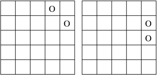


Since there are different pixel combinations, it is not feasible to use them directly to index into a LUT. Instead, the window is flipped and rotated such that the number and positions of pixels identified in the outer ring of the window match one of the thirteen cases shown in Fig. 18. This step is valid since the edge type is invariant with respect to a rotation and a flip of the window. The flipping and rotation operations are also designed using LUTs.
The color trapping step is implemented in a way similar to that for a window. Again, we observe that in consecutive positions, the windows have overlapping pixels which leads to the implementation of a faster, pixel-dependent approach. But since there are more overlapping pixels than when using the smaller () window, the running time can be further reduced for images containing regions of uniform colors. The average running time comparisons between JTHBCT03 [1], our pixel-independent LUT-based approach, and our pixel-dependent LUT-based approach are tabulated in Table III. As can be observed, by making use of the information for the overlapping pixels and LUTs, the pixel-dependent LUT-based approach is about faster than the pixel-independent approach, and more than three times faster than JTHBCT03.
| Approach Taken | Average Running Time00 0 The running time tests were performed on a machine with an Intel® Xeon(TM) processor and CPU speed of GHz for images , , , , and which are shown in Fig. 16. The running time is taken as an average of the average running time for the test images, each of which was tested times. (secs) |
|---|---|
| JTHBCT03 | |
| Pixel-independent | |
| Pixel-dependent (Algorithm 2) |
The memory required for processing a window of pixel data is tabulated in Table IV. The LUTs require approximately Mbytes of storage space. The total memory requirement for this approach, including dummy variables, image data ( lines of a full pixel page) and all the trapping parameters is around Mbytes.
| Data To Be Stored | Memory Required (bytes) | |
| LUTs for Edge Detection | No in OR00 0 Outer Ring | |
| One in OR††footnotemark: | ||
| Two s in OR††footnotemark: | ||
| Three s in OR††footnotemark: | ||
| Four s in OR††footnotemark: | ||
| Five s in OR††footnotemark: | ||
| Six s in OR††footnotemark: | ||
| LUTs for flipping and rotation ( flippings and rotations) | ||
| LUT for remapping edges | ||
| LUTs for checking neighborhoods | ||
| Trapping Parameters00 0 All the entries in the LUTs are stored as unsigned characters of size byte each. Edge detection LUTs were designed based on the number and position of pixels (Fig. 18) in the outer ring of the selected window. Trapping parameters include , , and (refer to [1]). | ||
| Subtotal | ||
| -Line Pixel Buffer | ||
| Other Variables Used | ||
| Total | ||
V Algorithm 3: Hybrid Method for Color Trapping with a Sliding Window

Replacing computations by LUTs, as we did in the previous section, is a well known way to reduce the complexity of an algorithm. However, it is important to keep in mind that while the use of look-up tables is often effective in gaining speed, memory is required to store this information. Moreover, since accessing memory also takes time, and since the access time may grow to some extent with the size of the LUT, converting computations into LUTs is sometimes not worthwhile from a CPU time perspective, especially when the computations they replace are quite simple.
The LUTs used in the previous section to replace the steps of color categorization, color density calculation, and trapping parameter calculation are small enough to yield an obvious speed gain. However, the LUT needed in Sec. IV-B to replace the feature extraction and the edge detection steps, where the , , and color arrangement is classified into one of three categories (edge1, edge2, or non-trappable), requires a significant amount of storage space. In fact, the Mbytes of storage required to implement this approach would be unacceptable for a low-cost formatter-based color printer. While the window approach has a significantly smaller storage requirement, it only provides an approximation to the edge classification results yielded by JTHBCT03. In this section, we present an alternative approach combining feature selection and the use of LUTs, which greatly reduces the storage space required without significantly increasing the computation time. This approach was developed using a training set consisting of typical print images with sizes ranging from pixels to pixels. This set of images contains various types of text, graphics and pictures.
The flow diagram of our hybrid approach to classify edges is shown in Fig. 19. This hybrid approach combines feature extraction and a -dimensional LUT to achieve fast and efficient edge classification. The first part of this approach consists of a prescreening step which identifies the most frequent and easily recognizable non-trappable color patterns using some simple features. This step is followed by a slightly more computationally expensive edge classification step consisting of extracting three integer valued features to index into a LUT separating trappable pixels (edge1 and edge2) from non-trappable pixels. A simple rule is then derived to distinguish edge1 from edge2 pixels. We now describe both the prescreening step and the edge classification step in greater details.
V-A Prescreening
One way to drastically reduce the computation time is to implement some prescreening rules that quickly identify a large amount of non-trappable pixels. By analyzing JTHBCT03, we observe the following simple prescreening rules.
where represents the center pixel in the window.
Here are short explanations for each of these prescreening criteria.
V-A1 White Pixel
In order to preserve the fidelity of the image and the outline of objects, white color pixels should remain unchanged. Therefore, if the center pixel of the window is white (, , , and ), this pixel can be ignored by the trapping algorithm.
V-A2 Uniform Color Region
Since gap or halo artifacts only occur around the edge areas, uniform regions, i.e., where all the pixels in the window have the same color, should not be trapped.
V-A3 Number of Inner O Pixels
If there is an pixel in the inner ring of the window, it is more likely that the window is a part of a picture instead of a text or graphic object. Therefore, pixels surrounded by such a color configuration should not be trapped.
V-A4 Number of Outer O Pixels
Gap or halo artifacts are more visible in images containing text or graphics with only a few density levels and sharp color transitions. For pictures with smooth color changes, there is no need for trapping. As the presence of many color pixels suggests that the window is likely to be part of a picture, the center pixel of a window with more than six ’s in the outer ring is not trapped.
V-B Edge Classification
Any window configuration that is not declared non-trappable at the prescreening step needs to be further analyzed in order to be classified into an edge category (edge1, edge2, or non-trappable). JTHBCT03 necessitates the extraction of discrete features in order to do this. Our aim is to classify the pixels as accurately as possible with as few and simple features as possible.
An important aspect of feature selection is to analyze the feature space distribution. Obviously, the distribution of the color values of the pixels is not uniform. That is, some color combinations occur more frequently than others in actual images. We used our training set to characterize the feature space distributions and the edge rules of JTHBCT03 to establish the ground truth for the edge type. We thoroughly analyzed all features used in JTHBC03 along with four additional ones, namely the amount of scatter (i.e. the principal values) along the principal directions of the color A and color B pixels, respectively. More precisely, we considered all possible choices of features, for , and computed a decision surface between the edge pixels and the non-edge pixels inside the corresponding feature space using a support vector machine algorithm. We chose to use no more than 6 features in order to limit the computational requirements of the algorithm. Note that we specifically did not use a dimension reduction technique such as principal component analysis (PCA) to reduce the dimensionality of the feature space, as our objective was to limit the number of features we would have to compute to a strict minimum. The principal values of the color A pixel arrangement were found to be quite useful in determining the presence of an edge. However, we found that the additional number of non-trappable edges identified using these features did not outweigh the computational cost of extracting these features and computing the value of the decision function. We found that extracting discrete features and using them to index into a LUT containing edge types was a more efficient approach. In fact, we found that only three simple features are needed to simulate JTHBCT03’s edge classification on non-trappable and trappable pixels with good accuracy. These are:
- 1.
– the number of pixels in the outer ring of the window;
- 2.
– the number of pixels in the inner window of the window;
- 3.
– the number of pixels in the outer ring of the window.
The resulting -dimensional feature plot is shown in Fig. 20. One notices that some points in the feature space correspond to more than one edge type. We resolve such ambiguities as follows: if JTHBCT03 considers all configurations with a given value of , , and to be non-trappable, then we declare them to be non-trappable as well; otherwise we trap them. Each possible three-tuple of these features is indexed into a LUT where the corresponding edge type is stored. Note that using a decision surface instead of a LUT would result in a much more complex decision rule, as the separation between the trappable and non-trappable pixels is not linear, as one can easily see from the feature plot.
Once a trappable pixel has been identified, its edge type (edge1 or edge2) needs to be determined. To do this, we check whether there is any color pixel in the inner window that is one of the nearest neighbors of the center pixel (i.e., pixels numbered , , , and as shown in Fig. 7). If there is, then the pixel is categorized as edge1, otherwise it is categorized as edge2. This is nearly always consistent with JTHBCT03’s rules.

V-C Numerical Experiments and Discussion
The computational burden added by the prescreening step is small considering the high number of non-trappable patterns it identifies. Indeed, our training set contains a total of (unique) non-trappable patterns, () of which are identified at the prescreening stage. However, non-trappable pixels occur statistically more often than trappable pixels. In fact, the prescreening step effectively filters out the majority () of all pixels, thus greatly diminishing the computational impact of the edge classification step.
Since our three-feature combination do not completely differentiate trappable pixels from non-trappable ones, our edge classification step sometimes makes mistakes. Indeed, as can be seen from Fig. 20, some non-trappable pixels (represented by green crosses) overlap with edge1 (represented by red circles) or edge2 pixels (represented by blue triangles) in our feature space. As explained earlier, such pixels end up being trapped. Overall, after the prescreening step, only (or ) of the unique patterns (i.e., not counting repetitions) do not overlap with an edge1 or edge2 pixel in the feature space, and are therefore declared non-trappable. However, this decision is always correct. Moreover, such patterns occur very often in images. In fact, in our training images, this set () of patterns corresponds to of all the non-trappable patterns entering the edge classification step. The remaining patterns are all declared trappable, which is oftentimes incorrect (in the sense that this is not the same classification as produced by JTHBCT03). But considering that, because of our highly efficient prescreening, only about of the patterns enter the edge classification step, the overall error rate is quite small, namely on average for our test images.
From a computational point of view, our overall algorithm is quite simple, as it requires very few operations per trapped pixel, in comparison with JTHBCT03. The detailed counts for each operation for JTHBCT03 and Algorithms and are given in Table V.
The experimental results for the hybrid approach, along with the two LUT-based approaches previously discussed, are tabulated in Table VI. For better comparison, we also included the average running time obtained by combining JTHBCT03 with our prescreening rules. As can be seen from the table, the hybrid approach is faster than JTHBCT03, with an average speed gain of a factor greater than four. It is also significantly faster than JTHBCT03 with prescreening. The time reduction for the hybrid approach is especially significant when the test image contains a lot of white area and uniform regions. For images containing pictures or more continuous tone objects such as , the advantage of the hybrid approach is somewhat less. This is most likely because we end up trapping more pixels than JTHBCT03. While this does not seem to affect the visual quality of the trapped image, it does slightly decrease the computational advantage. An example comparing trapping results is shown in Fig. 21. Notice that the difference consists of corner pixels, which are trapped with our algorithm but not with JTHBCT03. Since these corner pixels are located immediately next to the character edges, it seems that they should be trapped. In any case, the visual quality of the image is not affected by single pixel value changes.


VI Conclusion
Color trapping is an important image processing problem for color printing that has not previously been addressed in the scholarly research literature. We developed three different automatic color trapping algorithms based on JTHBCT03, a previously reported color trapping algorithm that was developed for hardware implementation. All of our proposed algorithms are amenable to software implementation, as they are significantly simpler computationally, both in terms of complexity (i.e., number of “if” statements, additions, and multiplications used per trapped pixel) and actual running time. Because of their low memory requirements, two of them are also amenable to firmware implementation on low-cost formatter-based printers.
In all three versions, we replaced mathematical computations for various trapping parameters by LUTs to reduce the computation time. The amount of memory required for these LUTs is small enough for all three methods to be deveoped in software. Our three proposed algorithms differ in the way the edge detection step (Step Four of JTHBCT03) is performed. In the first two versions proposed, this step is accomplished using LUTs. The first one (Algorithm 1) is a sliding window implementation which can effectively eliminate the gap and halo artifacts caused by a color plane misregistration of up to one pixel in extent as well as reduce the effect of two-pixel color plane misregistration. This algorithm runs in less than one tenth of the time of a software implementation of JTHBCT03. In addition to being software-friendly, the low memory requirements of this approach make it suitable for firmware implementation on low-cost printers. The second one (Algorithm 2), as in JTHBCT03, uses a sliding window, and can handle color plane mis-registrations of up to two pixels in extent. It runs in less than one third of the time of a software implementation of JTHBCT03. The memory requirements of this approach are too high for firmware implementation on low-cost printers, but it could be implemented as part of the printer driver or within a stand-alone application running on the host computer.
The third version is a hybrid approach that combines feature extraction and LUTs to increase the speed to more than four times that of a software implementation of JTHBCT03 while keeping the memory requirements very low (about 725 Kbytes). In particular, a computationally simple prescreening step is used to identify the majority of non-trappable pixels. The computational advantage of this approach is more pronounced when the input image contains text and graphic objects of uniform color regions and white areas. When a printed image contains many objects of continuous tones levels, the advantage over the other approaches is not as large since the prescreening step will not eliminate many non-trappable pixels. Moreover, because of its low memory requirement, Algorithm 3 is amenable to firmware implementation on low-cost printers, as well as software implementation.
| JTHBCT03 | LUT-based, Pixel- | LUT-based, Pixel- | Hybrid | |||
|---|---|---|---|---|---|---|
| independent Approach | dependent Approach | Approach00 0 Algorithm 3 | ||||
| Sliding window size | 00 0 Algorithm 1 | 00 0 Algorithm 2 | ||||
| Memory required (bytes) 00 0 Based on images of size pixels with lines stored in the memory at any given time. | ||||||
| No. of “if” statements per trapped pixel | ||||||
| No. of additions per trapped pixel | ||||||
| No. of multiplications per trapped pixel | ||||||
| File Name | JTHBCT03 | JTHBCT03 | LUT-based, Pixel- | Hybrid Approach | ||
| with Pre-Screening | dependent Approach | (Algorithm 3) | ||||
| () | Running | Running | Running | Running | Running | Edge Classification |
| Time ()00 0 The tests were performed on a Linux machine with Intel® Xeon(TM) processor and CPU speed of . Each image was tested independently ten times and the running time was computed as the average. | Time ()††footnotemark: | Time ()††footnotemark: | Time ()††footnotemark: | Time ()††footnotemark: | Error Rate()00 0 This represents the difference between our trapping results and those obtained by JTHBCT03. | |
| Window Size | — | |||||
All three of our proposed trapping algorithms provide a flexible structure for feature selection and training set collection, which could be easily modified for different trapping needs.
References
- [1] J. L. Trask, “Trapping methods and arrangements for use in printing color images,” U.S. Patent 6,549,303 B1, April 15, 2003.
- [2] R. V. Klassen, “Methods for automatic trap selection for correcting for separation misregistration in color printing,” U.S. Patent 6,345,117 B2, February 5, 2002.
- [3] P. Weinholz and V. Funke, “Method for generating trapping contours in a print page,” U.S. Patent 6,795,214, September 21, 2004.
- [4] S. Yhann, “Vector map planarization and trapping,” U.S. Patent 6,031,544, February 29, 2000.
- [5] S. C. Morgana, “Methods and systems for detecting the edges of objects in raster images using diagonal edge detection,” U.S. Patent 6,377,711 B1, April 23, 2002.
- [6] K. R. Deutsch, P. H. Bjorge, A. Blannin, E. J. Bean, D. L. Peltonen, and T. H. Roth, “Applying traps to a printed page specified in a page description language format,” U.S. Patent 5,542,052, July 30, 1996.
- [7] S. J. Bloomberg, “Electronic trapping system for digitized text and images,” U.S. Patent 5,581,667, December 3, 1996.
- [8] R. A. Dermer and E. C. Reifenstein, “Method for determining color boundaries for correcting for plate misregistration in color printing,” U.S. Patent 5,313,570, May 17, 1994.
- [9] R. A. Dermer, “Method for automatic trap selection for correcting for plate misregistration in color printing,” U.S. Patent 5,668,931, September 16, 1997.