Ultrawide-range photon number calibration using a hybrid system combining nano-electromechanics and superconducting circuit quantum electrodynamics
Abstract
We present a hybrid system consisting of a superconducting coplanar waveguide resonator coupled to a nanomechanical string and a transmon qubit acting as nonlinear circuit element. We perform spectroscopy for both the transmon qubit and the nanomechanical string. Measuring the ac-Stark shift on the transmon qubit as well as the electromechanically induced absorption on the string allows us to determine the average photon number in the microwave resonator in both the low and high power regimes. In this way, we measure photon numbers that are up to nine orders of magnitude apart. We find a quantitative agreement between the calibration of photon numbers in the microwave resonator using the two methods. Our experiments demonstrate the successful combination of superconducting circuit quantum electrodynamics and nano-electromechanics on a single chip.
The field of optomechanics allows to investigate the interaction of light with mechanical degrees of freedom. It enables the optical readout of the mechanical displacement [1] as well as the control of the mechanical state. Over the past decade, optomechanics has been successfully used to study the interplay between mechanical modes and quantized electromagnetic waves in a resonator on the quantum level [2, 3, 4, 5, 6, 7, 8, 9, 10, 11]. One successful experimental implementation is based on superconducting circuits as they, straightforwardly, can be operated in the resolved sideband limit [12].
In addition, superconducting nano-electromechanical circuits are compatible with the field of circuit quantum electrodynamics (cQED) [13] regarding fabrication technology, operation temperature and frequency range. In cQED, the strong [14, 15] and ultra-strong coupling regimes [16, 17, 18, 19] have been achieved and the generation of non-classical states of microwave light is well established [20, 21, 22, 23, 24, 25]. Therefore, the combination of nano-electromechanics with cQED is an ideal approach to delve into the quantum nature of mechanical motion.
Recent experiments [26, 27] show that the combination of a superconducting qubit, a microwave resonator and a nanomechanical element can enhance the phonon-photon interaction, allow for the controlled preparation of non-classical phonon states, and enable entanglement generation. One envisaged state preparation protocol is the generation of a non-classical microwave state in a microwave resonator coupled to both a qubit and a mechanical resonator. It makes use of a well-defined qubit state and its transfer to the mechanical system via a red-sideband drive pulse. For this, one critical parameter is the average photon number in the microwave resonator.
Here, we present an experimental study of a hybrid quantum system consisting of a transmon qubit, a doubly clamped high-Q nanomechanical string resonator, and a superconducting microwave resonator. We show that the average photon number determined from the ac-Stark shift and electromechanically induced absorption (EMIA) measurements are in good quantitative agreement.
The average photon number inside a microwave resonator with symmetric input/output (total) coupling rate is given by [28, 29]
| (1) |
Here, is the reduced Planck constant, denotes the detuning between the probe tone frequency and the resonant frequency . Additionally, describes the total loss rate of the microwave resonator given by the sum of the internal and external losses. The applied power describes the total calibrated output power of the microwave sources before sending it to the dilution refrigerator. Since the attenuation of the microwave lines and can only be estimated, we introduce the product as a calibration factor in Eq.. We demonstrate that can be quantified and corroborate its value via two independent approaches: (i) We measure the ac-Stark shift of the qubit transition frequency as a function of in the dispersive regime [30, 15] which we will call and (ii) we measure EMIA resulting from the electromechanical interference effect between the anti-Stokes field of the coupled electromechanical resonator system and a probe field [31, 32, 33, 34, 35] determining .
Taking the linewidth of the microwave resonator into account, the ac-Stark shift for a transmon qubit is given by [36, 37, 38]
| (2) |
when probing the microwave resonator on resonance . Here, the coupling between the transmon and the microwave resonator is and (cf. Fig. 1). The non-linearity of the transmon qubit is defined by , quantifying the deviation in energy of the second mode from twice the ground mode. Evidently, we can determine and, in turn, the calibration factor by measuring if we know the qubit parameters.
Next, we turn to EMIA which is known to result in an increase of the linewidth of the mechanical oscillator, leading to an effective linewidth given by [39, 33, 35]
| (3) |
Thus, measuring as a function of allows us to determine the calibration factor , if we know the relevant parameters of the mechanical oscillator and the electromechanical vacuum coupling constant . For this experiment, we chose , i.e., (cf. Fig. 1).
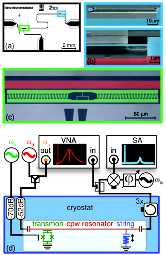
To quantitatively compare the resonator photon numbers determined with the two methods described above, we fabricate a hybrid device consisting of a superconducting microwave resonator, a transmon qubit and a doubly clamped nanomechanical string resonator, as depicted in Fig. 2. All these parts consist of superconducting aluminum thin films deposited by electron beam evaporation on a single crystalline silicon substrate. Patterning of the microwave and nanomechanical resonator is achieved by electron beam lithography and a lift-off process. After Al deposition, the sample is annealed at C for 30 minutes to generate a high tensile stress in the aluminum thin film. Then, the transmon qubit is defined again by electron beam lithography and fabricated using a two-angle shadow evaporation (see Ref. 37 and Ref. 38). In the last step, we release the nanostring resonator by reactive ion etching and critical point drying.
The m long, nm thick, and nm wide nano-string resonator has a mass of about pg. It is separated by a nm gap from the ground plane resulting in Hz. At the experimental temperature of mK we observe a mechanical resonance frequency of MHz, corresponding to a zero point fluctuation amplitude of fm. The low intrinsic mechanical linewidth of Hz corresponds to a thermal coherence time of s.
Tuning the transmon qubit to its minimum frequency, far away from the resonator frequency, we find the bare microwave resonator frequency GHz. Its linewidth depends on the setpoint of the transmon qubit and the photon occupation inside, see supplementary material for details.
As further detailed in the supplementary material, we find for the transmon qubit an eigenfrequency of GHz at the sweet spot, corresponding to a detuning of GHz, a transmon nonlinearity of MHz, and a transmon-resonator coupling of MHz.
For the measurement of the qubit transition frequency as a function of in the few photon regime, we tune the qubit to its sweet spot by an applied magnetic field. We then perform two-tone spectroscopy by driving the transmon qubit via its antenna while probing the resonator transmission with a microwave tone of varying power . In this way, we obtain the qubit frequency as a function of . In addition, we determine the microwave resonator linewidth as is influenced by this parameter. The product is shown in Fig. 3. As expected [c.f. Eq.], this product linearly depends on . We find a slope of s3nW. Combining this slope, as well as Eq., and the system parameters, we obtain s-1. Note that we used probe powers corresponding to , well below the critical photon number of , set by the assumptions of the dispersive limit [40, 41].
For the determination of the resonator photon numbers at higher occupations, we turn to the two-tone EMIA spectroscopy scheme (cf. Fig. 1). We set the red-sideband drive tone to and probe the anti-Stokes field with the probe tone , close to . Depending on the red-sideband drive amplitude, i.e. , we obtain the spectra depicted in Fig. 4(a). This figure shows the EMIA, which manifests as an additional absorption around . By fitting a Lorentzian lineshape to the EMIA data, we extract the effective interference linewidth .
A quantitative analysis of the transmission data shows an EMIA signature with a minimum corresponding to of the unperturbed microwave transmission parameter .
Figure 4 (b) displays the extracted EMIA linewidth as a function of the applied red-sideband drive power, confirming the linear increase predicted by Eq.. The calibration factor is determined by fitting Eq. to the data. Having characterized the sample parameters, the calibration factor and the intrinsic linewidth are the remaining free parameters in the model. We obtain s-1 and Hz. Using these results in combination with Eq., we can determine the average photon numbers in the microwave resonator in a range from about to photons.
In conclusion, we have successfully implemented a superconducting coplanar microwave resonator coupled to a transmon qubit and a nanomechanical string. Both the coupled transmon-MW resonator system and the nano-electromechanical system were investigated using microwave spectroscopy. These experiments allowed us to calibrate the MW resonator photon numbers by measuring the ac-Stark shift of the transmon qubit in the range from to photons and showed a calibration factor of s-1. For higher photon numbers, we used EMIA spectroscopy of the nanomechanical string to probe the resonator in a population range from to photons. By analyzing the linewidth of the transmission signature, we found a calibration factor s-1. Both attenuation coefficients and agree within . Please also note that these two methods determine average resonator photon numbers that are up to nine orders of magnitude apart.
The implementation of a transmon qubit, a high-quality nanostring resonator, and a microwave resonator on a single chip represents an important step towards the realization of quantum information storage in the vibrational degree of freedom of a mechanical element. Doubly clamped string resonators are interesting candidates in this context, due to their high mechanical quality factors, above , corresponding to a thermal coherence time from micro- to milliseconds at a moderate dilution fridge temperature of mK.
Acknowledgements.
This project has received funding from the European Union’s Horizon 2020 research and innovation program under grant agreement No 736943. We gratefully acknowledge valuable scientific discussions with J. Goetz, S. Weichselbaumer, and E. Xie.Appendix A Transmon qubit

The transmon qubit is positioned at the electric field anti-node of the coplanar waveguide resonator and is capacitively coupled to it. The qubit transition frequency can be varied by applying a magnetic flux to the dc-SQUID forming the tunable Josephson junction of the transmon qubit.
Figure 5(a) shows the transmission of a weak probe tone through the microwave resonator as a function of the applied magnetic flux for an average photon number of 1.7. At , we find a pronounced anti-crossing demonstrating the strong coupling between the transmon qubit and the resonator. From the peak separation at the avoided crossing, for occupations below one photon on average, we find a coupling strength of MHz. Additionally, we find the expected periodic flux dependence of the qubit transition frequency. When the transmon qubit is tuned to its minimum frequency, e.g. at , the detuning between the qubit and the resonator is so large that the uncoupled resonator frequency can be determined to GHz, with a linewidth of MHz.
When the qubit is far detuned from the resonator and therefore in the dispersive regime, the probed resonance frequency of the microwave resonator depends on the qubit state [30, 15]. Thus, driving the qubit with , allows to perform a two-tone spectroscopy of the qubit, as shown in Fig. 5(b) and (c). From panel (b) we determine a qubit frequency ( transition) of GHz at the sweet spot of .
To access the transmon anharmonicity we increase the amplitude of the drive tone at . For high drive powers two- and multi-photon processes become visible [42, 43]. In particular, we observe the two-photon transition at GHz corresponding to a transmon qubit anharmonicity of s-1. For transmon qubits the negative anharmonicity is equivalent to the charging energy [36]. Via [36] we find an ratio of 222 for the transmon qubit.
Appendix B Calibration of electromechanical coupling strengths
Next, we turn to the characterization of the nano-electromechanical system. We use the thermal fluctuations of the nanostring, similar to Refs. [33, 32, 44, 45], to determine the electromechanical vacuum coupling constant Hz. In detail, we use a frequency-modulated drive tone set to to probe the frequency fluctuations of the microwave resonator, caused by the thermal motion of the nanostring resonator. The transmitted signal is down-converted using a homodyne setup and analyzed with a spectrum analyzer.
The inset of Fig. 6 shows the microwave resonator sideband noise spectroscopy data representing the thermal motion of the nanostring at mK. We find a mechanical resonance frequency MHz with a linewidth of Hz, corresponding to a mechanical quality of about . The sharp peak on the left side originates from the frequency modulation of the probe tone (with a modulation frequency of MHz and a modulation depth of Hz) used for the calibration of the phase response of the microwave resonator (for details, see Refs. 33, 32, 44, 45). A quantitative comparison of this amplitude calibration peak with the amplitude of the thermal motion peak yields the integrated displacement noise and hence the vacuum coupling via [33, 32, 44]:
| (4) |
Here, we use the measurement bandwidth ENBW Hz. By repeating this measurement for various temperatures, we can calibrate the mechanical coupling with a finite back-action temperature (). Figure 6 shows the integrated displacement noise as a function of the temperature . We find a slope of kHzK and hence a vacuum coupling of
| (5) |
Appendix C Linewidth of the microwave resonator
As the linewidth (loss rate) of the microwave resonator influences the average photon number in the resonator, see Eq. (1) in the manuscript, we analyze it for each of the two calibration methods. We note that for the two methods different working points of the transmon qubit are used, indicated by A and B in Fig. 5(a), resulting in different behaviors. The observed dependencies are depicted versus applied power in Fig. 7 for the qubit (electromechanical) regime in panels (a) and (b), corresponding to the working points A and B, respectively.
The linewidth for the coupled qubit-resonator system is measured from pW up to the critical photon number. We find a linear dependence with an offset of MHz and a slope of kHz/nW. For the calibration this linear dependence is used to interpolate the product in Fig. 3 of the manuscript.
A non-trivial behavior is observed in the electromechanical regime. After a peak at mW, an increase up to MHz is found at mW. As the fluctuations in this dependence are rather small, we directly use the observed linewidth for our analysis. The measurement is done in-situ while determining the EMIA interference. We speculate that these fluctations of the linewidth arise from resistive elements in the Josephson junctions of the transmon qubit.
References
- [1] V. Braginsky, V. Braginskiĭ, F. Khalili, and K. Thorne, Quantum Measurements (Cambridge University Press, Cambridge, 1995).
- [2] M. Aspelmeyer, T. J. Kippenberg, and F. Marquardt, eds., Cavity Optomechanics, Quantum Science and Technology (Springer, Berlin, 2016).
- [3] E. E. Wollman, C. U. Lei, A. J. Weinstein, J. Suh, A. Kronwald, F. Marquardt, A. A. Clerk, and K. C. Schwab, Science 349, 952 (2015).
- [4] J.-M. Pirkkalainen, E. Damskägg, M. Brandt, F. Massel, and M. A. Sillanpää, Phys. Rev. Lett. 115, 243601 (2015a).
- [5] F. Lecocq, J. B. Clark, R. W. Simmonds, J. Aumentado, and J. D. Teufel, Phys. Rev. X 5, 041037 (2015).
- [6] C. U. Lei, A. J. Weinstein, J. Suh, E. E. Wollman, A. Kronwald, F. Marquardt, A. A. Clerk, and K. C. Schwab, Phys. Rev. Lett. 117, 100801 (2016).
- [7] V. C. Vivoli, T. Barnea, C. Galland, and N. Sangouard, Phys. Rev. Lett. 116, 070405 (2016).
- [8] S. G. Hofer, K. W. Lehnert, and K. Hammerer, Phys. Rev. Lett. 116, 070406 (2016).
- [9] M. Abdi, P. Degenfeld-Schonburg, M. Sameti, C. Navarrete-Benlloch, and M. J. Hartmann, Phys. Rev. Lett. 116, 233604 (2016).
- [10] K. Børkje, Phys. Rev. A 94, 043816 (2016).
- [11] M. Abdi, M. Pernpeintner, R.Gross, H. Huebl, and M. Hartmann, Phys. Rev. Lett. 114, 17360 (2015).
- [12] C. A. Regal, J. D. Teufel, and K. W. Lehnert, Nat. Phys. 4, 555 (2008).
- [13] R. J. Schoelkopf and S. M. Girvin, Nature 451, 664 (2008).
- [14] A. Wallraff, D. I. Schuster, A. Blais, L. Frunzio, R.-S. Huang, J. Majer, S. Kumar, S. M. Girvin, and R. J. Schoelkopf, Nature 431, 162 (2004).
- [15] A. Blais, R. Huang, A. Wallraff, S. Girvin, and R. Schoelkopf, Phys. Rev. A 69, 062320 (2004).
- [16] T. Niemczyk, F. Deppe, H. Huebl, E. P. Menzel, F. Hocke, M. J. Schwarz, J. J. Garcia-Ripoll, D. Zueco, T. Hümmer, E. Solano, A. Marx, and R. Gross, Nature Physics 6, 772 (2010).
- [17] A. Baust, E. Hoffmann, M. Haeberlein, M. J. Schwarz, P. Eder, J. Goetz, F. Wulschner, E. Xie, L. Zhong, F. Quijandría, D. Zueco, J.-J. G. Ripoll, L. García-Álvarez, G. Romero, E. Solano, K. G. Fedorov, E. P. Menzel, F. Deppe, A. Marx, and R. Gross, Phys. Rev. B 93 (2016).
- [18] P. Forn-Díaz, J. J. García-Ripoll, B. Peropadre, J.-L. Orgiazzi, M. A. Yurtalan, R. Belyansky, C. M. Wilson, and A. Lupascu, Nat. Phys. 13, 39 (2016).
- [19] F. Yoshihara, T. Fuse, S. Ashhab, K. Kakuyanagi, S. Saito, and K. Semba, Phys. Rev. A 95 (2017).
- [20] J. Johansson, S. Saito, T. Meno, H. Nakano, M. Ueda, K. Semba, and H. Takayanagi, Phys. Rev. Lett. 96, 127006 (2006).
- [21] D. I. Schuster, A. A. Houck, J. A. Schreier, A. Wallraff, J. M. Gambetta, A. Blais, L. Frunzio, J. Majer, B. Johnson, M. H. Devoret, S. M. Girvin, and R. J. Schoelkopf, Nature 445, 515 (2007).
- [22] M. Hofheinz, E. M. Weig, M. Ansmann, R. C. Bialczak, E. Lucero, M. Neeley, A. D. O’Connell, H. Wang, J. M. Martinis, and A. N. Cleland, Nature 454, 310 (2008).
- [23] C. Eichler, D. Bozyigit, C. Lang, L. Steffen, J. Fink, and A. Wallraff, Phys. Rev. Lett. 106, 220503 (2011).
- [24] E. P. Menzel, R. Di Candia, F. Deppe, P. Eder, L. Zhong, M. Ihmig, M. Haeberlein, A. Baust, E. Hoffmann, D. Ballester, K. Inomata, T. Yamamoto, Y. Nakamura, E. Solano, A. Marx, and R. Gross, Phys. Rev. Lett. 109, 250502 (2012).
- [25] Y. Chen, C. Neill, P. Roushan, N. Leung, M. Fang, R. Barends, J. Kelly, B. Campbell, Z. Chen, B. Chiaro, A. Dunsworth, E. Jeffrey, A. Megrant, J. Y. Mutus, P. J. J. O’Malley, C. M. Quintana, D. Sank, A. Vainsencher, J. Wenner, T. C. White, M. R. Geller, A. N. Cleland, and J. M. Martinis, Phys. Rev. Lett. 113, 220502 (2014).
- [26] J.-M. Pirkkalainen, S. U. Cho, F. Massel, J. Tuorila, T. T. Heikkilä, P. J. Hakonen, and M. A. Sillanpää, Nat. Commun. 6, 6981 (2015b).
- [27] A. O’Connel, M. Hofheinz, M. Ansmann, R. C. Bialczak, M. Lenander, E. Lucero, M. Neeley, D. Sank, H. Wang, M. Weides, J. Wenner, J. Martinis, and A. N. Cleland, Nature 464, 697 (2009).
- [28] M. Aspelmeyer, T. Kippenberg, and F. Marquardt, Rev. Mod. Phys. 86, 1391 (2014).
- [29] A. Clerk, M. Devoret, S. Girvin, F. Marquardt, and R. Schoelkopf, Rev. Mod. Phys. 82, 1155 (2010).
- [30] D. F. Walls and G. Milburn, Quantum optics, 2nd ed. (Springer-Verlag Berlin Heidelberg, 2008).
- [31] J. Teufel, D. Li, M. Allman, K. Cicak, A. Siruis, J. Whittaker, K. Lehnert, and R. Simmonds, Nature 471, 204 (2011).
- [32] F. Hocke, X. Zhou, A. Schliesser, T. Kippenberg, H. Huebl, and R. Gross, New J. Phys. 14, 179 (2012).
- [33] X. Zhou., F. Hocke, A. Marx, H. Huebl, R. Gross, and T. Kippenberg, Nat. Phys. 9, 179 (2013).
- [34] T. Bagci, A. Simonsen, S. Schmid, L. G. Villanueva, E. Zeuthen, J. Appel, J. M. Taylor, A. Sørensen, K. Usami, A. Schliesser, and E. S. Polzik, Nature 507, 81 (2014).
- [35] V. Singh, S. J. Bosman, B. H. Schneider, Y. M. Blanter, A. Castellanos-Gomez, and G. A. Steele, Nat. Nanotechnol. 9, 820 (2014).
- [36] J. Koch, T. Yu, J. Gambetta, A. Houck, D. Schuster, J. Majer, A. Blais, M. Devoret, S. Girvin, and R. Schoelkopf, Phys. Rev. A 76, 042319 (2007).
- [37] J. Goetz, F. Deppe, P. Eder, M. Fischer, M. Muetting, J. Martinez, S. Pogorzalek, F. Wulschner, E. Xie, K. Federov, A. Marx, and R. Gross, Quantum Sci. Technol. 2, 025002 (2017a).
- [38] J. Goetz, S. Pogorzalek, F. Deppe, K. Federov, P. Eder, M. Fischer, F. Wulschner, E. Xie, A. Marx, and R. Gross, Phys. Rev. Lett. 118, 103602 (2017b).
- [39] S. Weis, R. Rivière, S. Deléglise, E. Gavartin, O. Arcizet, A. Schliesser, and T. J. Kippenberg, Science 330, 1520 (2010).
- [40] M. Boissonneault, J. M. Gambetta, and A. Blais, Phys. Rev. A 79, 013819 (2009).
- [41] J. Raftery, D. Sadri, S. Schmidt, H. E. Türeci, and A. A. Houck, Phys. Rev. X 4 (2014).
- [42] L. S. Bishop, J. M. Chow, J. Koch, A. A. Houck, M. H. Devoret, E. Thuneberg, S. M. Girvin, and R. J. Schoelkopf, Nat. Phys. 5, 105 (2008).
- [43] J. Braumüller, J. Cramer, S. Schlör, H. Rotzinger, L. Radtke, A. Lukashenko, P. Yang, S. T. Skacel, S. Probst, M. Marthaler, L. Guo, A. V. Ustinov, and M. Weides, Phys. Rev. B 91, 054523 (2015).
- [44] M. L. Gorodetsky, A. Schliesser, G. Anetsberger, S. Deleglise, and T. Kippenberger, Opt. Express 18, 23236 (2010).
- [45] P. Weber, J. Güttinger, A. Noury, J. Vergara-Cruz, and A. Bachtold, Nat. Commun. 7, 12496 (2016).