Arrested coalescence of viscoelastic droplets: Ellipsoid shape effects and restructuring
Abstract
The stable configurations formed by two viscoelastic, ellipsoid-shaped droplets during their arrested coalescence has been investigated using micromanipulation experiments. Ellipsoidal droplets are produced by millifluidic emulsification of petrolatum into a yield stress fluid that preserves their elongated shape. The liquid meniscus between droplets can transmit stress and instigate movement of the droplets, from their initial relative position, in order to minimize doublet surface energy. The action of the liquid meniscus causes the ellipsoidal droplets to undergo rolling and restructuring events because of their unique ellipsoid shape and associated variation in surface curvature. The final configuration of the droplets is shown to be controlled by the balance between interfacial Laplace pressure and internal elasticity, as well as a constraint force that resists complete minimization of surface energy. Geometric and surface energy calculations are used to map the possible and most likely configurations of the droplet pairs. Experimental deviations from the calculations indicate the magnitude and potential origin of the constraint force resisting full equilibration. Droplet aspect ratio and elasticity are both shown to influence the degree of restructuring and stability of the droplets at energy extrema. Higher aspect ratios drive greater restructuring and better agreement with final doublet configurations predicted by energy minimization. Lower elasticity droplets undergo secondary deformations at high aspect ratios, further broadening the space of possible morphologies.
Introduction
Emulsions are broadly used in food Friberg et al. (2004), pharmaceutical Gupta et al. (2016), polymeric Vandebril et al. (2010), petroleum Zylyftari et al. (2015), biomimetic Claessens et al. (2006); Pontani et al. (2012), bijel Mohraz (2016), and even explosive Bdzil and Stewart (2007) materials. Coalescence, when emulsion droplets recombine into a larger fluid volume, is a critical dynamic in commercial products that can be harmful, when product instabilities occur or dispersion quality is lost, or beneficial, when a structure of linked droplets imparts rheology modification and desirable texture to a fluid like, for example, whipped cream.
Arrested coalescence occurs when coalescence begins minimizing droplet surface energy but is halted by a physical resistance like interfacial or internal droplet elasticity Studart et al. (2009); Pawar et al. (2011); Pawar et al. (2012). Arrested coalescence is commonly observed in dairy products, where a network of solid milk fat crystals forms inside of oil droplets Boode and Walstra (1993). The poroelasticity of the droplet allows coalescence to begin because of the liquid phase permeating the solid crystal skeleton, but is then halted when the crystal structure can not be deformed enough for full coalescence Pawar et al. (2011); Pawar et al. (2012). Arrested coalescence is important to the study of food products, as it is a key phenomenon used to build structure, texture, and aesthetic perception of most dairy products Fredrick et al. (2010), but recent work has shown applications of arrested droplets in other materials as well.
Colloidal materials are often developed under conditions when arrested coalescence is significant, as when partially molten metal particles assemble into clusters van der Kooij and Sprakel (2015) or when evaporating films of solvent squeeze suspended particles or droplets Manoharan et al. (2003); Sacanna et al. (2010); Sacanna (2011); Nabavi et al. (2017). The final structure and performance of such systems is highly dependent on the packing and structure of constituent spherical colloids, and it is important to know the effects of dynamic capillary processes in these systems on the evolution of structure as assembly proceeds. For example, it was shown recently that spherical viscoelastic droplets can significantly reorient as a result of liquid capillary effects during arrested coalescence, spontaneously driving the droplets into more compact packing arrangements even though initially added at less-optimal positions Dahiya et al. (2017). However, meniscus effects also play a significant role in shape changes by aggregates of non-spherical solid colloids, enhancing self-assembly Basavaraj et al. (2006); Madivala et al. (2009); Yunker et al. (2011); Phillips et al. (2014), sintering of metal structures Nabavi et al. (2017), additive manufacturing Prileszky and Furst (2016), and aggregation of non-spherical fat solids Kim and Vanapalli (2013).
Droplets are typically spherical because interfacial tension acts to minimize surface energy. In some viscoelastic droplets, however, the internal rheology of the droplets can preserve non-spherical shapes Caggioni et al. (2014); Caggioni et al. (2015); Bayles et al. (2018), and is used to enhance deposition onto biological surfaces Spicer et al. (2017); Spicer et al. (2017) and food emulsion rheology Giermanska et al. (2007); Thivilliers et al. (2008); Thivilliers-Arvis et al. (2010). There is then also a need to understand arrested coalescence and its shape-change dynamics for non-spherical droplets. We are interested in these dynamics for two reasons. One is to understand how non-spherical droplets assemble in systems whose rheology, texture, and quality are determined by droplet microstructure. A second is to map the motion of non-spherical shapes driven by the competing effects of interfacial liquid meniscus motion and droplet mechanical properties. Dynamic shape change using physical mechanisms, like geometry and interfacial driving forces J.-P. Peraud and Lauga (2014), will be a critical aspect of future directed and active material assembly efforts at the nanoscale, where Brownian motion is significant Cho et al. (2010), and at the microscale, where thermal motion no longer dominates Py et al. (2007); Leong et al. (2007).
We study here the binary arrested coalescence of monodisperse ellipsoidal droplets with controlled aspect ratios produced in a microfluidic device. Because of the importance of motion to shape-change, and of final state to self-assembly, we examine both aspects here. We first explore the dynamics of an ellipsoidal droplet being pulled around another by a fluid meniscus as a means of understanding possible shape change and self-assembly mechanisms. Many more configurations are possible for arrested pairs of ellipsoidal droplets than for spherical droplets, and we use the results of an energy minimization model to map the full extent of possible behavior while comparing with our experimental findings.

Experimental
Methods and Materials
Oil-in-water emulsions were prepared by combination of an oil and aqueous phase during microchannel flow. The system has been characterized in a number of past works Pawar et al. (2012); Caggioni et al. (2014); Caggioni et al. (2015); Dahiya et al. (2016); Dahiya et al. (2017) and is a reproducible model of more complex systems like milk fat Thiel et al. (2016). The aqueous phase was a dispersion of neutralized 0.15% w/w Carbopol 846. The oil phase was a mixture of petrolatum containing 50% wax solids (Unilever) and varying levels of hexadecane (99% Sigma Aldrich) to form mixtures containing either 30% or 40% w/w wax solids. The two components were heated to 80 °C until the petrolatum melted and fully mixed with the hexadecane. The mixture then crystallized as a dispersion of solid crystals inside a liquid oil phase Pawar et al. (2012).
Millifluidics
Droplets were generated in a two-part co-flow millifluidic device made from a round 1.1 mm ID glass capillary (Vitrocom), with a 90 μm ID tip created using a Model P-97 Micropipette Puller (Sutter Instruments), inserted into a 1.1 mm ID square capillary (Vitrocom). Oil phase was pumped through the inner, round capillary while the continuous phase flows through the outer square tube Utada et al. (2005). Droplets with varying size and aspect ratio were produced by adjusting the dispersed phase flow rate between 0.08-1.2 mL/min while keeping the continuous phase at 0.08 mL/min.
As seen in Figure 1A, droplets with irregular shapes were first produced as a result of the yield stress of the droplet phase () Caggioni et al. (2014); Caggioni et al. (2015). Relatively uniform ellipsoidal shapes were then produced by immediately passing the dispersion through a section of the channel held at 40 ℃ by an external heating source Prileszky and Furst (2016); Caggioni et al. (2018). The internal structure of the droplet partially melts during this step, reducing its yield stress and reshaping the droplet to a uniform ellipsoid with a maximum curvature set by the equality of the droplet and continuous phase yield stress values Caggioni et al. (2014); Caggioni et al. (2015); Bayles et al. (2018). The yield stress of the w/w aqueous Carbol 846 continuous phase () created a “liquid mold” environment that preserved the deformed droplet shape until it could cool and regain its own yield stress Pairam et al. (2013); Burke et al. (2015). Image analysis of calibrated experimental micrographs was carried out using ImageJ software Schneider et al. (2012) to quantify droplet size, aspect ratio, and long axis orientation. Doublets are studied only when they are level in the image plane to avoid errors from out-of-plane movements, consistent with our theoretical descriptions.
Figure 1B shows three examples of different aspect ratio ellipsoids produced using this method. Coalescence studies were carried out by carefully transferring droplets to a volume of aqueous 0.3% w/w microfibrous cellulose yield stress fluid Emady et al. (2013). Micromanipulation was performed on droplets, inside a small liquid sample placed on glass slides, using a 3-axis system (Narishige International) mounted on an inverted microscope (Motic AE31). Droplets were grasped, using suction applied by adjusting the height of a small fluid reservoir connected to a microcapillary in the sample volume, and then the droplets were pushed together by slow manipulation to initiate coalescence Pawar et al. (2011).
Results and Discussion
Arrested coalescence can occur when the elasticity of an internal solid network in two droplets is sufficient to balance the interfacial Laplace pressure driving the coalescence process Pawar et al. (2012). As a result, the balance can be altered by, for example, increasing the internal solids concentration of the droplets in order to increase the droplet elasticity. When the symmetry of the system is broken, for example when a third droplet is added to an existing arrested pair, restructuring can occur when the meniscus pulls the droplets in a direction that minimizes the assembly’s surface energy Dahiya et al. (2017). We consider the potential for such effects on ellipsoidal droplets here by studying the simplistic case of an ellipse rolling around a second one.
Rolling ellipsoid model
If the experimental droplets behave as hard solids when moved around one another, a simple rolling model can be used to study some aspects of droplet motion. It also provides a basis for comparison with experimental results using droplets that can undergo some degree of deformation as a result of their internal elastic network Pawar et al. (2012). The two-dimensional path of the center of an ellipse rolling around another, congruent, ellipse is described in Cartesian coordinates by the curve Abbena et al. (2017):
| (1) |
where and are the major and minor axes of each ellipse and the aspect ratio is defined as:
| (2) |
Equation 1 assumes motion of the ellipses begins with the two shapes aligned end-to-end along their long axes and ignores slip between the two shapes during motion. Visualizations of calculated ellipse paths were produced using code developed by Mahieu Mahieu (2014). Figure 2A shows several plots of the calculated trajectory, in red, of the center of mass of a blue ellipse, rolling around the perimeter of a second, identical, red ellipse. As the aspect ratio of the ellipses increases, the moving ellipse path transitions from perfectly circular, for , to an increasingly complex path. Regions of the path with sharp changes in curvature are evident when the ellipses are aligned edge-to-edge, increasing in magnitude as the ellipse aspect ratio increases. Figure 2B shows a series of images of two ellipsoidal droplets just after coalescence has initiated. Here the images have been rotated to fix the position of the lower droplet and enhance study of subsequent changes. The liquid film bridging the droplets radially moves out from the point of initial contact, reducing overall surface energy, and in the process pulls the two droplets together. Similar behavior was seen for the case of two spherical droplets undergoing arrested coalescence Pawar et al. (2012). However, here the non-spherical droplets also experience a change in relative orientation as the interfacial force pulling them together rolls one droplet along the edge of the other, similar to the action of ellipsoidal gears Zar et al. (2008). A red dot has been placed at the center of mass of the upper ellipsoid, allowing us to track changes in orientation as a result of the meniscus movement. The droplets largely move as rigid bodies and never move in a way that increases surface area, consistent with previous observations of spherical droplets moved by meniscus effects Dahiya et al. (2017). There is also some noticeable deformation of the droplets as the meniscus pulls them together in the last frame of Figure 2B, where overlap with the other ellipse is apparent, also in agreement with the behavior of spherical droplets Pawar et al. (2012). We highlight this effect using a drawn ellipse overlay in Figure 2B that indicates the degree of overlap and deformation of the drops as a result of elastic deformation Pawar et al. (2012). The last frame in Figure 2B represents the final stable position of this doublet, even though we might naively expect the two droplets to relax further. Some resistance to the reduction of surface energy must be acting to halt further motion, perhaps because of local friction or deformation of the internal elastic microstructure. Comparison of the center of mass positions in Figure 2B with calculated paths for this doublet will allow us to quantify the magnitude of any effects on trajectory.
In Figure 2C we plot a trajectory calculated following the method used to generate Figure 2A along with the experimentally-determined positions of the center of mass of the upper droplet in Figure 2B to assess any non-idealities. We see good general agreement of the experimental and calculated paths, though the real droplet is systematically closer to the second droplet than predicted. The deviation likely results from the small strain the droplets experience as the internal solid network deforms elastically Pawar et al. (2012). The last few points in Figure 2C deviate more significantly from the calculated path, indicating there may be stronger deformation occurring late in the process and that such deviations are time- and position-dependent. Variations in the deformation during arrested coalescence between the two droplets will cause variations in frictional resistance to movement, complicating our description of the process. We do not quantify strain in these systems, as we did for spherical droplets Pawar et al. (2012), as the more complex ellipsoidal shape here complicates such a description. The two-dimensional calculations do not fully account for the three-dimensional nature of the ellipsoids produced here, and also ignore the effects of the liquid film between droplets. They do, however, communicate the basic principle at work here: the movement of one ellipsoidal droplet around another’s perimeter is a strong function of the varying curvature of the ellipsoids. Below we improve on the above description, by simulating the three-dimensionality of the ellipsoids as well as the effects of the liquid film that imposes the stress driving motion, providing a more comprehensive understanding of the arrested coalescence behavior of ellipsoidal droplets.

Surface Minimization Model
To map the energy landscape experienced by the ellipsoidal doublets as a function of their relative orientation, we simulated the fluid-fluid interface with Surface Evolver Brakke (1992). The droplets are modeled as one-sided level set constraints around which the area of the fluid-fluid interface is minimized at fixed enclosed volume as a function of the relative position of the two droplets. In our model, we suppose the interface has uniform surface tension. Hence the area of the interface is proportional to surface energy and minimizing the area is equivalent to minimizing the surface energy. In previous work, this strategy allowed us to correctly predict the critical angle below which the menisci of two spherical droplets overlapped with that of a third droplet being added, causing reconfiguration of the triplet shape Dahiya et al. (2017).
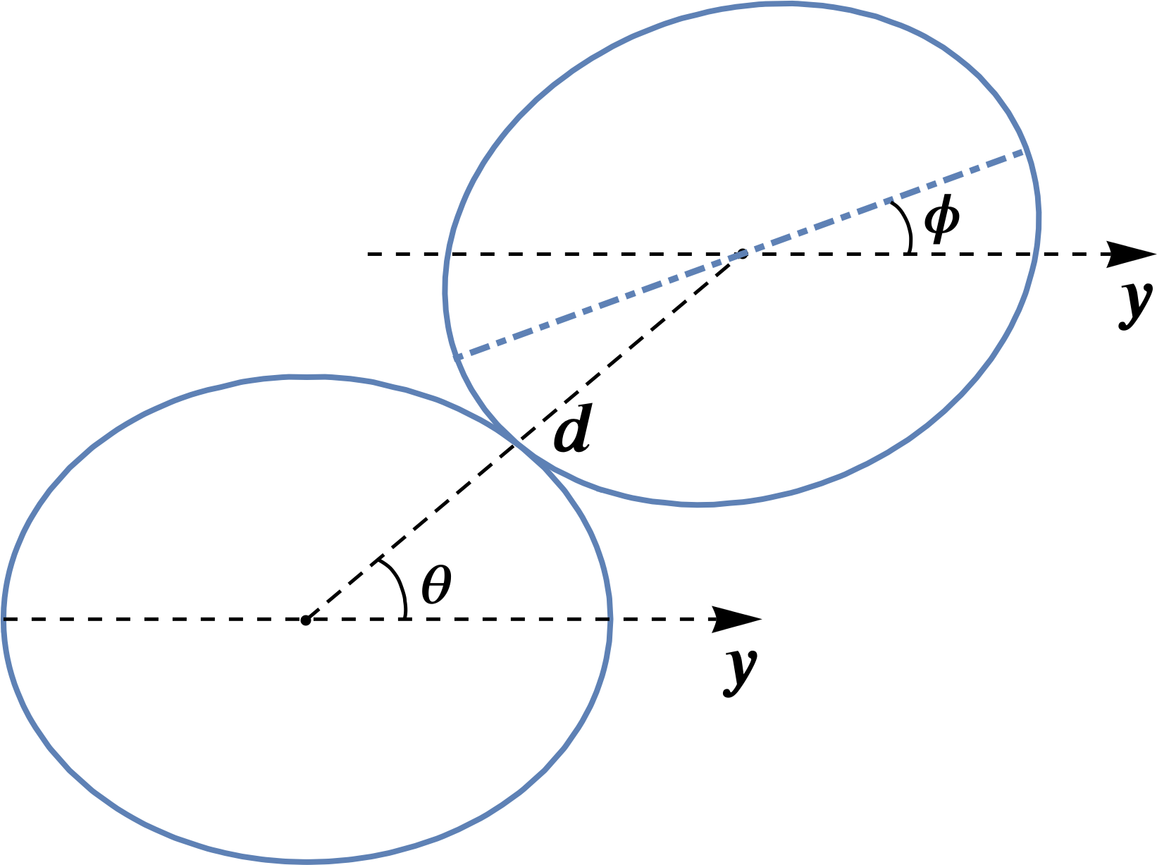
The computational geometry is depicted in Figure 3: the coordinate system is oriented such that the axis is along the major axis of one of the ellipsoids. The center of mass of the other is at the zenithal angle from this axis and oriented at an angle to it. Due to the symmetry of the system, the domain of is from to and from to . For every and , the distance is calculated using the overlap algorithm proposed by Perram and Wertheim Perram and Wertheim (1985) such that the second ellipsoid is positioned just in contact with the surface of the first ellipsoid. The ellipsoids impose level set constraints on the fluid interface,
| (3) |
| (4) |
where , is the center of the second ellipsoid at , is the rotational matrix of around the axis and is the diagonal matrix with entries ). The surface is then minimized with a fixed volume , slightly greater than the volume of the two ellipsoids in order to allow the formation of a meniscus. The volume of the enclosing fluid is clearly a relevant quantity here, as it will set the available free liquid to act on the droplets during their coalescence and arrest. We use a constant value in the simulations for simplicity.
Figure 4 shows a contour plot of the surface energy, for ellipsoids of aspect ratio , calculated using Surface Evolver simulations for the entire range of values of angles and . Three-dimensional renderings of simulated ellipsoidal droplet pairs are also shown for representative regions to aid the interpretation of the results and allow comparison with experiment. Two minimum surface energy regions are visible at high values in combination with either low or high values, consistent with the case when two ellipsoids are joined at their long edges and minimize their total surface area. A maximum in surface energy occurs where the two ellipsoidal droplets are parallel and arranged end on, at low values in combination with either low or high values, maximizing the doublet surface area. A saddle point exists where the droplets are perpendicularly aligned in a ‘T’ configuration. An analogous energy diagram was computed for single nanocylinders at a flat liquid interface, finding similar regions of stability for similar orientations Lewandowski et al. (2006).
Generally, when the droplets initially make contact at arbitrary angles we expect their orientation to evolve down the energy gradient towards the minimum because the motion occurs in a viscous quasistatic regime, a prediction that will be robustly tested in the subsequent section. The droplets in the doublet are, however, also subject to forces from the internal structure and the opposing meniscus driving forces on the ellipsoid surface. Divergence from the behavior predicted by surface energy alone therefore allows us to assess the relative importance of these other terms to the final shape of the doublet.
Figures 4B-H show several examples of experimental ellipsoidal doublets forming and restructuring, to various degrees, before reaching their final arrested state. The droplets all have an aspect ratio of and contain solids by weight. As a result, the droplet deformation is expected to be relatively low during arrested coalescence and any observed restructuring by the fluid meniscus will be reproducible and easily compared with the predictions of Figure 4A. Figure 4A suggests we might only find stable configurations of ellipsoidal doublets at the two energy minima. However, Figures 4B-H show a much wider range of final doublet states can be formed, without necessarily exhibiting the restructuring we might expect. Figures 4B and H show the largest amount of restructuring, with varying by and , respectively. In Figure 4B, the restructuring halts with the two ellipsoids oriented at angles of and , close to the energy minimum in Figure 4A but several contour lines outside of it. Clearly some type of constraint force, possibly the elastic resistance of internal structure, affects the restructuring process and can arrest the system at a point that is not stationary with respect to the surface tension term. In Figure 4H, an energetic minimum is attained by the pair of ellipsoids at values of and . Other initial states lead to much less restructuring, expanding the range of forms that can be obtained by ellipsoidal droplet arrested coalescence. Because the ellipsoidal droplet shape is anisotropic, this implies that the initial orientation of the droplets’ major axes will have a strong effect on the subsequent restructuring brought about by the meniscus.
Figures 4C-G restructure very little from their initial position, moving at most in Figure 4E. In Figure 4C, two ellipsoids initiate contact at angles of and and do not experience any restructuring over time, despite this representing the highest energy configuration calculated in Figure 4A. This is because the meniscus forces that normally drive restructuring vanish at an energetic maximum, creating an unstable stationary state. However, additional influences present, such as elastic resistance of the internal structure, may stabilize the stationary state against collapse. Figure 4D shows the case when two ellipsoids are initially brought together into the minimum energy configuration at the top right of Figure 4A. Here the system restructures only very slightly. Figures 4 E-G also do not restructure significantly, and they all come into contact in various realizations of the saddle point conditions in Figure 4A, an area of intermediate stability where two ellipsoids are arrested at, or near, right angles to one another. The system may be stabilized at the saddle point, as in Figure 4F. If the doublet is initially configured slightly away from the saddle point, as in Figures 4E and G, the system evolves towards the energy minimum slightly but nonetheless is arrested close to the saddle point. Again, this may be explained by the additional constraint forces from the internal structure.

Because the ellipsoid dimensions determine the amount and distribution of surface area in the droplets, we also explore the effects of droplet aspect ratio on our above results. Calculated energy contour plots are shown in Figure 5 for several ellipsoidal droplet aspect ratios, as well as two different internal droplet solids levels. Our simulation can account for changes in solids level by varying the volume of fluid enclosed by the simulated interface, but we use a fixed value here because it doesn’t change the shape of the energy contour plot. The contours in each plot are labeled with surface energy relative to the surface energy minimum. Increasing aspect ratio alters the shape of the regions of energy minima and maxima as a result of the geometric changes in the droplets. For example, the width of the minimum energy region for the three aspect ratios with solids in Figure 5 increases as increases, spanning a wider range of values. The effect is geometric, and is caused by the higher ellipsoid edge length at larger values.
The instantaneous values of and for a number of experimental doublets, during coalescence and restructuring, are plotted as colored trajectory lines on top of the contour plots in Figure 5 to show the extent of restructuring that occurs for different starting positions and compositions. The contour plot provides a useful map to summarize many different experiments and compare the effects of multiple system variables. For droplets containing solids, at all aspect ratios, the trajectories plotted in Figure 5 all move in the direction of decreasing energy. Interestingly, for , most do not reach a minimum, consistent with the example in Figure 4B, likely because of inherent solid and fluid resistance to flow and movement. As the aspect ratio of the droplets containing solids is increased in Figure 5, the lengths of the trajectories increase significantly, indicating a greater degree of movement and restructuring during arrested coalescence. Although fewer data were taken for the larger aspect ratios, droplets with and reproducibly move from an intermediate stability level, at a calculated saddle point, entirely into the minimum energy region. Despite the simplicity of the model, agreement between experiment and predicted final configurations is surprisingly good when meniscus-induced restructuring is this significant. It is reasonable to expect that longer ellipsoids will have stronger driving forces to reduce surface energy, restructuring much more significantly than droplets with smaller aspect ratios. The concept of a driving force, here reduction of surface energy, and a resistance, here an elastic or frictional force, suggests that increasing droplet solids level and elasticity will also affect the restructuring process.
Figure 5 plots trajectories for a number of doublet systems containing solids as they restructure. For an , the trajectory sizes are of similar or smaller size compared to the trajectories of the droplets containing solids in Figure 5. At the higher solids level in Figure 5, most of the restructuring observed at both aspect ratios moves the doublets down the energy gradient, but does not move them into the calculated energy minimum state, likely because of a larger elastic resistance to deformation. Interestingly, we observe two instances at solids where the droplets move up the energy gradient, possibly because of heterogeneities in the solid structure of the droplet. Even more extreme effects of the larger aspect ratios are observed at the lower solids concentration studied.

The top row of Figure 6 shows a time sequence of images of two ellipsoids containing solids, with , as they are brought together, begin coalescence, and then arrest. The images in Figure 6 are captured between crossed polarizers to highlight the solid phase regions of the structures as they move. In the first few frames of Figure 6, the droplets move together steadily because of migration of the fluid meniscus, reducing doublet surface area and moving it from a relatively high energy configuration, near the saddle-point in the middle of Figure 4A, toward the low-energy region of the upper-right quadrant of Figure 4A. The time interval is the same for each frame, but the distance moved from the frame at to the frame at is about , a significant acceleration. Much like elliptical gears, we find that ellipsoidal droplets can convert a relatively constant driving force, expansion of the fluid meniscus, into a variable speed movement. Such forces also have a strong effect on the individual droplets.
The bottom row of Figure 6 highlights the behavior of the two droplets after reaching a near-final conformation: edge-to-edge alignment in a low energy state. An overlaid line, connecting the lower ellipsoid’s endpoints with its midpoint, is used to visualize the subsequent deformation of the ellipsoid as the meniscus continues to expand completely across the length of the doublet. Here the deflection of the lower ellipsoid is in the last frame, about of the ellipsoid length. The significant deformation of the ellipsoids by the meniscus force only occurs once the droplets have been brought together at the energetic minimum with respect to their relative orientation. At this point, no further reduction in the meniscus area can occur by rotations; however deformation of the ellipsoids can bring their ends into closer contact, reducing the overall contact area at the expense of elastic reorganization of the internal structure. The lower solids level of the ellipsoids means that this deformation is feasible. Past measurements of the petrolatum system Caggioni et al. (2014) indicate droplets containing solids have a yield stress, and an interfacial tension . The stress needed to deform the droplet must then be of the same order as the droplet yield stress Caggioni et al. (2014). Assuming the Laplace pressure sets the magnitude of applied stress, we can calculate the necessary maximum radius of the fluid meniscus, R, to cause such a change from:
| (5) |
Using Equation 5, we solve to obtain and, since the measured meniscus radius is more on the order of , conclude that the meniscus force is more than sufficient to cause the changes observed in Figure 6. Such deformation is only observed when droplets have low solids levels and high aspect ratios, but Equation 5 indicates it could be avoided by increasing the elastic resistance to droplet deformation Caggioni et al. (2014); Caggioni et al. (2015); Bayles et al. (2018).

Conclusions
The processes of self-assembly and restructuring of pairs of ellipsoidal droplets undergoing arrested coalescence have been studied here using stable droplets, produced in a millifluidic process, with varying aspect ratios. The ellipsoidal shape of the droplets enables restructuring and deformation behavior that is significantly different from that exhibited by spherical droplets Dahiya et al. (2017). Ellipsoidal droplets exhibit more complex trajectories, and a wider range of motion, than spheres Dahiya et al. (2017) during meniscus-driven restructuring. The experimentally observed dynamics approach, but don’t always attain, theoretical predictions of the most stable configurations with respect to geometry and surface energy. Small amounts of deformation occur for all droplets, reducing the radius of their path when compared to that predicted by the locus of an ellipse rotating around a second ellipse. The final configuration of the droplets also deviates from more developed three-dimensional simulations of arrested coalescence of ellipsoids, likely because of elastic and frictional resistance to the stresses transmitted by the fluid meniscus. The resistance can be tuned by adjusting the dimensions and solids fraction of the droplets, potentially allowing control of larger structure assembly and restructuring.
We are particularly interested in how irregularly-shaped, non-Brownian, particles and droplets can be assembled and organized by the action of a fluid meniscus to achieve changes in shape and to form larger-scale structures. This work demonstrates limits on the ability to control shape change and other dynamics using droplets containing solid particles or viscoelastic microstructures. Varying the aspect ratio of the droplets controls the extent of restructuring that is possible before a stable configuration is reached. All ellipsoidal droplets experience some restructuring, mostly moving toward lower surface energy states. Low aspect ratio ellipsoids form mostly metastable configurations during restructuring, while higher aspect ratios mostly converge to energy minima, though increased elasticity can offset such effects. Tuning the rheology of the droplets impacts the final configurations, likely by affecting the significance of local and variable deformation of individual droplets. The importance of this work is its droplet-level study of arrested coalescence and restructuring mechanisms for non-spherical shapes. It is hoped the insights can be used to create accurate predictions of larger-scale aggregates formed via assembly and meniscus-driven restructuring Prileszky and Furst (2016), enabling design of emulsion microstructures and their mechanical properties Bayles et al. (2018). Applications are possible in areas as diverse as food product development Kim and Vanapalli (2013), advanced material creation Feng et al. (2013), and additive manufacturing Prileszky and Furst (2016).
References
- Friberg et al. (2004) Friberg, S., Larsson, K., Sjoblom, J., Eds. Food emulsions; CRC Press, 2004; Vol. 132.
- Gupta et al. (2016) Gupta, A.; Eral, H. B.; Hatton, T. A.; Doyle, P. S. Soft Matter 2016, 12, 2826–2841.
- Vandebril et al. (2010) Vandebril, S.; Vermant, J.; Moldenaers, P. Soft Matter 2010, 6, 3353.
- Zylyftari et al. (2015) Zylyftari, G.; Ahuja, A.; Morris, J. F. Energy Fuels 2015, 29, 6286–6295.
- Claessens et al. (2006) Claessens, M.; Tharmann, R.; Kroy, K.; Bausch, A. R. Nature Physics 2006, 2, 186–189.
- Pontani et al. (2012) Pontani, L.-L.; Jorjadze, I.; Viasnoff, V.; Brujic, J. Proceedings of the National Academy of Sciences 2012, 109, 9839–9844.
- Mohraz (2016) Mohraz, A. Curr. Op. Colloid Int. Sci. 2016, 25, 89–97.
- Bdzil and Stewart (2007) Bdzil, J. B.; Stewart, D. S. Ann. Rev. Fluid Mech. 2007, 39, 263–292.
- Studart et al. (2009) Studart, A. R.; Shum, H. C.; Weitz, D. A. J. Phys. Chem. B 2009, 113, 3914–3919.
- Pawar et al. (2011) Pawar, A.; Caggioni, M.; Ergun, R.; Hartel, R.; Spicer, P. Soft Matter 2011, 7, 7710–7716.
- Pawar et al. (2012) Pawar, A.; Caggioni, M.; Hartel, R.; Spicer, P. Faraday Discussions 2012, 158, 341–350.
- Boode and Walstra (1993) Boode, K.; Walstra, P. Colloid Surf. A 1993, 81, 121–137.
- Fredrick et al. (2010) Fredrick, E.; Walstra, P.; Dewettinck, K. Adv. Colloid Interface. Sci. 2010, 153, 30–42.
- van der Kooij and Sprakel (2015) van der Kooij, H. M.; Sprakel, J. Soft Matter 2015, 11, 6353.
- Manoharan et al. (2003) Manoharan, V. N.; Elsesser, M. T.; Pine, D. J. Science 2003, 301, 483.
- Sacanna et al. (2010) Sacanna, S.; Irvine, W.; Chaikin, P. M.; Pine, D. J. Nature 2010, 464, 575–578.
- Sacanna (2011) Sacanna, S. Current Opinion in Colloid & Interface Science 2011, 16, 96–105.
- Nabavi et al. (2017) Nabavi, S. A.; Vladisavljevic, G. T.; Zhu, Y.; Manovic, V. Environ. Sci. Technol. 2017, 51, 11476–11483.
- Dahiya et al. (2017) Dahiya, P.; DeBenedictis, A.; Atherton, T. J.; Caggioni, M.; Prescott, S. W.; Hartel, R. W.; Spicer, P. T. Soft Matter 2017, 13, 2686–2697.
- Basavaraj et al. (2006) Basavaraj, M. G.; Fuller, G. G.; Fransaer, J.; Vermant, J. Langmuir 2006, 22, 6605–6612.
- Madivala et al. (2009) Madivala, B.; Fransaer, J.; Vermant, J. Langmuir 2009, 25, 2718–2728.
- Yunker et al. (2011) Yunker, P.; Still, T.; Lohr, M.; Yogh, A. G. Nature 2011, 476, 308–311.
- Phillips et al. (2014) Phillips, C. L.; Jankowski, E.; Krishnatreya, B. J.; Edmond, K. V.; Sacanna, S.; Grier, D. G.; Pine, D. J.; Glotzer, S. C. Soft Matter 2014, 10, 7468–7479.
- Prileszky and Furst (2016) Prileszky, T. A.; Furst, E. M. Chemistry of materials 2016, 28, 3734–3740.
- Kim and Vanapalli (2013) Kim, J.; Vanapalli, S. A. Langmuir 2013, 29, 12307–12316.
- Caggioni et al. (2014) Caggioni, M.; Bayles, A.; Lenis, J.; Furst, E.; Spicer, P. Soft Matter 2014, 10, 7647–7652.
- Caggioni et al. (2015) Caggioni, M.; Lenis, J.; Bayles, A.; Furst, E.; Spicer, P. Langmuir 2015, 31, 8558–8565.
- Bayles et al. (2018) Bayles, A. V.; Prileszky, T. A.; Spicer, P. T.; Furst, E. M. Langmuir 2018, 34, 4116–4121.
- Spicer et al. (2017) Spicer, P.; Caggioni, M.; Lenis, J.; Bayles, A. Shape-Changing Droplet. European Patent EP 2909299 B1, Procter and Gamble Co., 2017.
- Spicer et al. (2017) Spicer, P.; Caggioni, M.; Lenis, J.; Bayles, A. Non-Spherical Droplet. US Patent 9,597,648, Procter and Gamble Co., 2017.
- Giermanska et al. (2007) Giermanska, J.; Thivilliers, F.; Backov, R.; Schmitt, V.; Leal-Calderon, F. Langmuir 2007, 23, 4792–4799.
- Thivilliers et al. (2008) Thivilliers, F.; Laurichesse, E.; Leal-Calderon, F.; Schmitt, V. Langmuir 2008, 24, 13364–13375.
- Thivilliers-Arvis et al. (2010) Thivilliers-Arvis, F.; Laurichesse, E.; Schmitt, V.; Leal-Calderon, F. Langmuir 2010, 26, 16782–16790.
- J.-P. Peraud and Lauga (2014) J.-P. Peraud,; Lauga, E. Phys Rev E 2014, 89, 043011.
- Cho et al. (2010) Cho, J. H.; James, T.; Gracias, D. H. Advanced Materials 2010, 22, 2320–2324.
- Py et al. (2007) Py, C.; Reverdy, P.; Doppler, L.; Bico, J.; Roman, B.; Baroud, C. N. Phys Rev Lett 2007, 98, 156103.
- Leong et al. (2007) Leong, T. G.; Lester, P. A.; Koh, T. L.; Emma, K.; Gracias, D. H. Langmuir 2007, 23, 8747–8751.
- Dahiya et al. (2016) Dahiya, P.; Caggioni, M.; Spicer, P. T. Phil. Trans. R. Soc. A 2016, 374, 20150132.
- Thiel et al. (2016) Thiel, A. E.; Hartel, R. W.; Spicer, P. T.; Hendrickson, K. J. J. Amer. Oil Chem. Soc. 2016, 1–11.
- Utada et al. (2005) Utada, A. S.; Lorenceau, E.; Link, D. R.; Kaplan, P. D.; Stone, H. A.; Weitz, D. A. Science 2005, 308, 537–541.
- Prileszky and Furst (2016) Prileszky, T. A.; Furst, E. M. Langmuir 2016, 32, 5141–5146.
- Caggioni et al. (2018) Caggioni, M.; Traini, D.; Young, P. M.; Spicer, P. T. Powder Technology 2018, 329, 129–136.
- Pairam et al. (2013) Pairam, E.; Vallamkondu, J.; Koning, V.; van Zuiden, B. C.; Ellis, P. W.; Bates, M. A.; Vitelli, V.; Fernandez-Nieves, A. PNAS 2013, 110, 9295–9300.
- Burke et al. (2015) Burke, C. J.; Mbanga, B. L.; Wei, Z.; Spicer, P. T.; Atherton, T. J. Soft Matter 2015, 11, 5872–5882.
- Schneider et al. (2012) Schneider, C. A.; Rasband, W. S.; Eliceiri, K. W. Nature Methods 2012, 9, 671–675.
- Emady et al. (2013) Emady, H.; Caggioni, M.; Spicer, P. Journal of Rheology 2013, 57, 1761.
- Abbena et al. (2017) Abbena, E.; Salamon, S.; Gray, A. Modern differential geometry of curves and surfaces with Mathematica; Chapman and Hall/CRC, 2017.
- Mahieu (2014) Mahieu, E. Ellipse Rolling around Another Ellipse Project, Wolfram Demonstrations Published: July 15, 2014. 2014.
- Zar et al. (2008) Zar, I.; Sa, T.; Engineering, P.; Str, N. Archive of Mechanical Engineering 2008, 55, 275–292.
- Brakke (1992) Brakke, K. A. Experimental mathematics 1992, 1, 141–165.
- Perram and Wertheim (1985) Perram, J. W.; Wertheim, M. Journal of Computational Physics 1985, 58, 409–416.
- Lewandowski et al. (2006) Lewandowski, E. P.; Searson, P. C.; Stebe, K. J. J. Phys. Chem. B 2006, 110, 4283–4290.
- Feng et al. (2013) Feng, L.; Pontani, L.-L.; Dreyfus, R.; Chaikin, P.; Brujic, J. Soft Matter 2013, 9, 9816–9823.