Near-bound states in the radiation continuum in circular array of dielectric rods
Abstract
We consider E polarized bound states in the radiation continuum (BICs) in circular periodical arrays of infinitely long dielectric rods. We find that each true BIC which occurs in an infinite linear array has its counterpart in the circular array as a near-BIC with extremely large quality factor. We argue analytically as well as numerically that the quality factor of the symmetry protected near-BICs diverges as where is a material parameter dependent on the radius and the refraction index of the rods. By tuning of the radius of rods we also find numerically non-symmetry protected near-BICs. These near-BICs are localized with exponential accuracy outside the circular array but fill the whole inner space of the array carrying orbital angular momentum.
pacs
42.25.Fx,41.20.Jb,42.79.DjI Introduction
Recently confined electromagnetic modes above the light line, bound states in the continuum (BICs) were shown to exist in periodic arrays of long dielectric rods [1, 2, 3, 4, 5, 6, 7, 8, 9, 10, 11, 12, 13, 14, 15, 16, 17, 18].

Among numerous types of BICs it is worthy to emphasize the BICs which can propagate either cross to rods [10, 17] or along the axis of periodicity of the system [7]. In practice there are no infinite arrays of rods. In the array of a finite number of rods the BICs become quasi-BICs with finite Q-factor which diverges as or even as [19, 20]. These results are in agreement with the theorem on the absence of BICs in the bounded domain which is complement of an unbounded domain [21, 22]. The BICs can appear only in unbounded domain. Physically occurrence of the BICs in the infinite array of rods is a result of periodicity of the array that quantizes the radiation continua in the form of diffraction continua [10, 23]. Then if the frequency is below the cut-off of the second diffraction continuum the BIC is embedded into the first diffraction continuum. Note that the second diffraction continuum is also important providing a bound space for the BIC [10].
Moreover the scattering of acoustic waves and water surface waves by array of cylinders was extensively studied in series of papers [24, 25]. The remarkable case of a circular array of cylinders was considered in Refs. [26, 27, 28, 29]. Numerical results of strong confinement of light in a circular array of dielectric pillars [30] and symmetry protected quasi-BICs with exponentially high quality factor in the circular array of dielectric nanorods [31] were reported recently. We reexamine these results for E polarized symmetry protected BICs in the circular array of infinitely long cylindrical dielectric rods and demonstrate the patterns of quasi-BICs with extremely large quality factors. Following [28] we define such BICs as near-BICs.
We present mathematical arguments in favor of exponentially large quality factors of the symmetry protected near-BICs in the circular array of dielectric rods. In addition we find numerically the non-symmetry protected near-BICs by tuning the rod radius. In contrast to the symmetry protected near-BICs they fill the internal space of the circular array. The circular array of rods support non-symmetry protected near-BICs with orbital angular momentum (OAM). Finally, we demonstrate the counterparts of the BICs in the linear array embedded into two and three diffraction continua which fill only a part of the inner space of circular array. The diffraction continua for the linear chain is given by plane waves
| (1) |
where
| (2) |
and enumerates the diffraction continua for the periodical chain of rods with the period .
II Scattering theory for circular array of cylinders
Following Ref. [33] (see quite similar procedure described in ref. [24] for the Neumann boundary conditions at the surfaces of rigid cylinders) we present the general E polarized solution at the vicinity of the j-th rod for the electric field directed along the rods as follows
| (3) |
where the first term presents the incident wave from a point-like source placed at the center of circular array as sketched in Figs. 2 and 3
| (4) |
the second term is a contribution of the other rods and the field emanating from the -th rod. and are the polar coordinates of the radius-vector in the local coordinate systems of the -th rod as shown in Fig. 2. We introduce substitutions
| (5) |
where (see Fig. 2) and use the Graf formula [33]:
| (6) |
where definitions of angles and distances are shown in Fig. 2. That allows us to write the following relations between the amplitudes and :
| (7) |
Periodicity of the circular array of rods allows us to write
| (8) |
where is the Bloch number. In particular for we have from Eqs. (7) and (8)
| (9) |

Finally, we close Eq. (9) which relates incident amplitude with emanating amplitude by equation
| (10) |
where is the diagonal component of the S-matrix of a circular dielectric rod
| (11) |
, and is the permittivity of the rod of radius . Substituting Eq. (10) into Eq. (9) we can formulate the basic equation
| (12) |
where the matrix elements are given by
| (13) |
and according to Eq. (4)
| (14) |
III Far-field zone solution
Outside the rods for the solution with the Bloch wave number takes the following form [33]
| (15) |

Now we can write the electric field in the far-field zone at the point shown in Fig. 3 by the use of the asymptotic form of the Hankel function
| (16) |
We have where all three radius-vectors are shown in Fig. 3. For we can approximate
| (17) |
Therefore in the far-field zone the electric field can be approximated as follows
| (18) |
Now we apply to this equation a mathematical observation of exponential convergence of sums [32]
| (19) |
The sum is converged as follows
| (20) |
for some and
| (21) |
where is a periodical analytical function. Therefore we can write Eq. (18) as follows
| (22) |
Using the identity for the Bessel functions
| (23) |
we have for the electric field (22) in the far-zone
| (24) |
IV The solution inside the circular array of rods
Now we consider the solution inside the circular array. We have for the electric field
| (25) |
Let us use the Graf formula in order to transfer the solution at local position defined by to the solution in the global system of coordinates defined by the radius-vector . We have
| (26) |
Substitution of this equation into Eq. (25) gives
| (27) |
Due to the equality
| (28) |
where is an integer, we can simplify Eq. (27) as follows
| (29) |
V Near-BICs
For the infinite periodical arrays if a source is switched off, there are exceptional cases with selected real eigenfrequencies embedded into the radiation continuum as was briefly reviewed in the Introduction. These exceptional cases define BICs which are localized in the vicinity of the arrays [1, 2, 3, 4, 5, 6, 7, 8, 9, 10, 11, 12, 13, 14, 15, 16, 17, 18]. Let us consider what happens to these BICs if to roll up a finite array into a circle. For the solution could vanish in the far-field zone we have to imply that all [22]. That in turn requires that there is no electric field in the near-zone too according to Eq. (25), i.e., the solution equals zero everywhere. However, if only exponential smallness is required in the far-field zone, for we can imply a softer condition for the amplitudes
| (30) |
as it is seen from Eq. (24). Therefore, the solution turns to zero in the far-field zone with exponential accuracy. While in the near-field zone the solution given by Eq. (29) is finite to be referred to as a near-BIC.
Now we show that this formulation of the near-BICs in the circular arrays is consistent with source-free Eq. (12)
| (31) |
which has no solution for real frequencies. However, by analytical continuation of the frequency into the complex plane we can find a solution of Eq. (31) which has an extremely small imaginary part . Numerics show that the corresponding eigenmode satisfies Eq. (30).
V.1 The symmetry protected BICs
We start a consideration with the solution which is odd relative to in local system of coordinates as sketched in Fig. 3. For (standing waves) we can take all amplitudes and as independent of the site index . Hence we can rewrite the solution (3) in the vicinity of of the rods as follows
| (32) | |||
| (33) |
For the odd solution we imply the following equalities
| (34) |
then Eq. (30) is fulfilled. For the directional array of infinite number of rods the most trivial symmetry protected BIC is the solution which is odd relative to each rod in the array direction. The solution of the symmetry protected BIC is presented in Refs. [10, 11]. Then the coupling of the BIC with the first diffraction continuum obviously equals zero.
Below we hold in numerics two parameters of dielectric rods fixed: the permittivity (silicon rods)and the period (the angular distance between centers of the rods). The frequency is measured in terms of where is the light velocity. In Fig. 4 we show as the pole of the matrix behaves with growth of the number of rods for different types of the symmetry protected near-BICs. One can see that the real part of this complex eigenvalue limits to the frequency of the symmetry protected true BIC in the infinite array of rods.


Fig. 5 (a) shows the pattern of electric field of the symmetry protected BIC in the linear array of dielectric rods. Fig. 5 (b) and (c) show its circular counterparts in the circular array of 15 and 25 rods respectively. Fig. 6 shows other examples of the symmetry protected BICs given in Refs. [10, 11].


The patterns of the near-BICs as well as their exponentially large Q-factors point out an analogy with the whispering gallery modes (WGM) shown in Fig. 5 (d) which also show exponentially large Q-factor [38]. However in the present case the Q-factor proportional to while for the WGM where is the order of the Bessel function. Finally in Fig. 7 we present numerical results for the parameter as dependent on the material parameters.
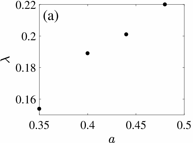

V.2 Non-symmetry protected BICs embedded into the first diffraction continuum
However the above analogy of BICs in the circular array of rods with the WGMs is terminated if to consider the non-symmetry protected BICs which need tuning of the rod radius. Some examples of these BICs borrowed from Refs. [10, 17] are shown in Fig. 8 (a). Its counterpart in the circular array is even for relative to in local system of coordinates. In that case Eq. (30) can be fulfilled by tuning, for example, the rod radius . Figs. 8 (c) and (d) demonstrate what happens with these BICs if to forld the rods in circle and then optimize the rod radius . Because of the symmetry of the infinite array of rods in respect to up and down by tuning of the rod radius we can achieve zero coupling of the BIC with both half radiation spaces above and below of the array. In the circular array of rods we can achieve extremely small coupling of the near-BIC to trap light against emanation outside the circle. However we can not simultaneously suppress emanation inside the circle. As the result one can see that the BIC mode fills whole inner space of the circular array as demonstrated in Fig. 8.


The next aspect of the non-symmetry protected near-BICs is related to dependence of the Q-factor on . For each the near-BIC needs in optimization of the rod radius to give rise to extremely large Q-factor similar to the symmetry protected near-BICs (see Fig. 4 (a)). However in practice it is easier to optimize the rod radius for some selected number of rods. Currently we selected . Then change of the number of rods with the same radius gives the dependence of the Q-factor shown in Fig. 9 which has non-monotonic behavior. One can see that for all except the circular array of rods can support only resonances with the Q-factors in the range from hundreds till ten thousands.

Let us leave the material parameters unchange but take the number of rods, say, . Then the solution becomes resonant state which strongly emanates EM field into the first diffraction radiation continuum as shown in Fig. 8 (c) and (d). The quality factors are taken from Fig. 9.
Till now we considered near-BICs with the zero Bloch vector , i.e., with no angular dependence as shown in Fig. 8 (b). Fig. 10 (a) shows the near-BIC with OAM and Fig. 10 (b), and (c) show the near-BICs with .


V.3 BICs embedded into a few diffraction continua
In the infinite linear array of rods there are also BICs embedded into a few diffraction continua given by Eqs. (1) and (2). They are symmetry protected relative to the first continuum and tuned by the radius of rods to be embedded into the other continua. [10]. Owing to high frequencies these BICs occur at the rod radius smaller compared to the BICs embedded into the first diffraction continuum only. In this section we present their circular counterparts of such BICs. We begin with the BIC embedded into the first and second diffraction continua given by and of the linear array of rods for . It has the Bloch vector along the array equaled to [10] as shown in Fig. 12 (a).


Respectively its circular counterpart has the same Bloch vector .
Fig. 13 (a) presents the BIC with the Bloch vector embedded into three diffraction continua with for [10] and Fig. 13 (b) shows its circular counterpart. However in order to achieve high Q-factors of these BICs the number of rods is to be rather high, 40 and 50.


Above we have presented the symmetry protected BICs which localized around the rods (see Figs. 5 and 6) and non-symmetry protected BICs which fill whole inner space of the circular array (see Figs. 8, 10 and 11). One can see that BICs embedded into two or more diffraction continua (see Figs. 12 and 13) have radial range of localization less than the radius of circle . That radial behavior of the BICs is results of radial behavior of the Bessel functions of high order. For we have an asymptote through the Airy function [34]
The Airy function tends to zero when its argument exceeds zero. From Eq. (29) we have and . Therefore the radial width of BIC localization can be evaluated as
| (35) |
If the BIC is embedded into only the first diffraction continuum we have . Then from Eq. (35) we obtain that the BIC occupies whole inner region inside the circle. For the BIC embedded into the first and second diffraction continua we have that gives the
In particular for the near-BIC shown in Fig. 13 we have and to obtain that is close the numerical result shown in Fig. 13. At last, for the BIC embedded into three continua we have and respectively from Eq. (35) obtain
that again is in good agreement with Fig. 14. Surprisingly we revealed the near-BIC with shown in Fig. 14 in the circular array of 30 rods whose linear counterpart is not the BIC but the narrow resonance.
VI Summary
We considered light trapping by circular array of infinitely long dielectric rods. Each BIC, symmetry protected and non-symmetry both, found in the linear arrow of rods [10, 11, 17] has its circular counterpart, near-BICs. Although the trapped light modes can not be rigorously considered as the BIC in the circular array of rods because of arguments presented in Refs. [21, 22], we have presented analytical arguments in favor that the Q-factor of the symmetry protected BICs with zero Bloch number grows exponentially with the number of rods. Numerically this important result presented in Fig. 4 (a) and independently by Lu and Liu [31]. In particular for 25 rods the Q-factor of the symmetry protected trapped modes reaches values of order similar to the whispering gallery modes as demonstrated in Fig. 5. In practice such Q-factors make the near-BICs in the circular array indistinguishable from true BIC in the infinite array of rods that allowed us to define them as the near-BICs. The symmetry protected near-BICs with zero Bloch number are close in nature to the whispering gallery modes (WGMs) (see Fig. 5 (d)) whose high Q factor is explained by total internal reflection but not by destructive interference.
However the analogy with the WGM is ended if to proceed to the symmetry protected near-BICs with non zero Bloch number or the non-symmetry protected near-BICs. The cardinal difference between these near-BICs and the WGM is that the former fills whole inner space of the circular array. As dependent on the Bloch vector the inner structure of the near-BIC defines the orbital angular momentum (OAM) in respect to circular array and irrespectively to the solution inside the individual rod. After abrupt change of the radius of the circle these near-BICs with OAM emanate in the surrounding space in the form shown in Fig. 11. Also the Q-factor of the non-symmetry protected near-BICs can be reached extremely large however we can not conclude that there is exponential behavior of the Q-factor with the number of rods because of necessity to tune the radius of rods for each . As it was shown in Ref. [10] there are BICs in the infinite linear array of rods embedded into a few diffraction continua. In the present paper we have presented counterparts of these BICs in the circular array of rods. They compose rather interesting feature which is partial filling of the inner space of circular array. Note one can consider the H polarized near-BICs in the circular array of dielectric rods with similar results.
Acknowledgments: We acknowledge discussions with Andrey Bogdanov and Dmittrii Maksimov. This work was partially supported by Ministry of Education and Science of Russian Federation (State contract N 3.1845.2017) and RFBR grants 16-02-00314 and 17-52-45072.
References
- [1] S. Shipman and S. Venakides, ”Resonance and bound states in photonic crystal slabs”, SIAM J. Appl. Math. 64, 322 (2003).
- [2] S.P. Shipman and S. Venakides, ”Resonant transmission near non robust periodic slab modes”, Phys. Rev. E71, 026611 (2005).
- [3] D. C. Marinica, A. G. Borisov, and S.V. Shabanov, ”Bound States in the Continuum in Photonics”, Phys. Rev. Lett. 100, 183902 (2008).
- [4] R.F. Ndangali and S.V. Shabanov, ”Electromagnetic bound states in the radiation continuum for periodic double arrays of subwavelength dielectric cylinders”, J. Math. Phys. 51, 102901 (2010).
- [5] Chia Wei Hsu, Bo Zhen, J. Lee, Song-Liang Chua, S.G. Johnson, J.D. Joannopoulos, and M. Soljačić, ”Observation of trapped light within the radiation continuum, Nature, 499, 188 (2013).
- [6] S. Weimann, Yi Xu, R. Keil, A.E. Miroshnichenko, A. Tunnermann, S. Nolte, A.A. Sukhorukov, A. Szameit, and Yu.S. Kivshar, ”Compact Surface Fano States Embedded in the Continuum of Waveguide Arrays”, Phys. Rev. Lett. 111, 240403 (2013).
- [7] Chia Wei Hsu, Bo Zhen, Song-Liang Chua, S.G. Johnson, J.D.Joannopoulos, and M. Soljačić, ”Bloch surface eigen states with in the radiation continuum”, Light: Science and Applications 2, 1 (2013).
- [8] Bo Zhen, Chia Wei Hsu, Ling Lu, A.D. Stone, and M. Soljačić, ”Topological Nature of Optical Bound States in the Continuum”, Phys. Rev. Lett. 113, 257401 (2014).
- [9] Yi Yang, Chao Peng, Yong Liang, Zhengbin Li, and S. Noda, ”Analytical Perspective for Bound States in the Continuum in Photonic Crystal Slabs”, Phys.Rev. Lett. 113, 037401 (2014).
- [10] E.N. Bulgakov and A.F. Sadreev, ”Bloch bound states in the radiation continuum in a periodic array of dielectric rods”, Phys. Rev. A90, 053801 (2014).
- [11] Zhen Hu and Ya Yan Lu, ”Standing waves on two-dimensional periodic dielectric waveguides”, J. Optics, 17, 065601 (2015).
- [12] J.M. Foley, S.M. Young, and J.D. Phillips, ”Symmetry-protected mode coupling near normal incidence for narrow-band transmission filtering in a dielectric grating”, Phys. Rev. B 89, 165111 (2014).
- [13] Maowen Song, Honglin Yu, Changtao Wang, Na Yao, Mingbo Pu, Jun Luo, Zuojun Zhang, and Xiangang Luo, ”Sharp Fano resonance induced by a single layer of nanorods with perturbed periodicity”, Opt. Express, 23, 2895-2903 (2015).
- [14] Chang-Ling Zou, Jin-Ming Cui, Fang-Wen Sun, Xiao Xiong, Xu-Bo Zou, Zheng-Fu Han, and Guang-Can Guo, ”Guiding light through optical bound states in the continuum for ultrahigh-Q microresonators”, Laser Photonics Rev. 9, 114119 (2015).
- [15] Lijun Yuan and Ya Yan Lu, ”Diffraction of plane waves by a periodic array of nonlinear circular cylinders,” Phys. Rev. A 94, 013852 (2016).
- [16] Zhixin Wang, Hanxing Zhang, Liangfu Ni, Weiwei Hu, and Chao Peng, ”Analytical Perspective of Interfering Resonances in High-Index-Contrast Periodic Photonic Structures”, IEEE J. Quant. Electr. 52, 6100109 (2016).
- [17] Lijun Yuan and Ya Yan Lu, ”Propagating Bloch modes above the lightline on a periodic array of cylinders”, J. Phys. B: At. Mol Opt. Phys. 50, 05LT01 (2017).
- [18] Z.F. Sadrieva, I.S Sinev, K.L. Koshelev, A. Samusev, I.V. Iorsh, O. Takayama, R. Malureanu, A.A. Bogdanov, and A.V. Lavrinenko, ”Transition from optical bound states in the continuum to leaky resonances: role of substrate and roughness,” ACS Photonics 4, 723 (2017).
- [19] I.Ya. Polishchuk, A.A. Anastasiev, E. A. Tsyvkunova, M.I. Gozman, S. V. Solovov, and Yu.I. Polishchuk, ”Guided modes in the plane array of optical waveguides”, Phys. Rev. A 95, 053847 (2017).
- [20] E.N. Bulgakov and D.N. Maksimov, ”Light enhancement by quasi-bound states in the continuum in dielectric arrays”, Opt. Express, 25, 14134 (2017).
- [21] D. Colton and R. Kress, Inverse Acoustic and Electromagnetic Scattering Theory, 2nd ed. (Springer,Berlin,1998), p.165.
- [22] M.G. Silveirinha, ”Trapping light in open plasmonic nanostructures”, Phys. Rev. A 89, 023813 (2014).
- [23] E.N. Bulgakov and A.F. Sadreev, ”Bound states in the continuum with high orbital angular momentum in a dielectric rod with periodically modulated permittivity”, Phys. Rev. A96, 013841 (2017).
- [24] C.M. Linton and D.V. Evans, ”The interaction of waves with arrays of vertical circular cylinders”, J. Fluid Mech. 215, 549 (1990).
- [25] H.D. Maniar and J.N. Newman, ”Wave diffraction by a long array of cylinders”, J. Fluid Mech. 339 309 (1997).
- [26] A.C. Ludwig, ”Wire grid modeling of surfaces”, IEEE Trans. Antennas and Propagation AP-35, 1045 (1987).
- [27] R.J. Paknys, ”The near field of a wire grid model”, IEEE Trans. Antennas and Propagation 39, 994 (1991).
- [28] D.V. Evans and R. Porter, ”Near-trapping of waves by circular arrays of vertical cylinders”, Appl. Ocean Res. 19, 83–99 (1997).
- [29] G. Fikioris and K. Matos, ”Near Fields of Resonant Circular Arrays of Cylindrical Dipoles” IEEE Trans. Antennas and Propagation 50, 97 (2008).
- [30] C. Sieutat, R. Peretti, J.-L. Leclercq, P. Viktorovitch, and X. Letartre, ”Strong confinement of light in low index materials: the Photon Cage”, Opt. Express 21, 20015–20022 (2013).
- [31] Hai-bin Lü and Xiaoping Liu, ”Trapped modes with extremely high quality factor in the subwavelength ring resonator composed of dielectric nanorods”, arXiv:1709.08006 (2017).
- [32] L.N. Trefethen and J.A.C. Weideman, ”The exponentially convergent trapezoidal rule”, SIAM Review 56, 385 (2014).
- [33] D. Maystre, S. Enoch, and G. Tayeb, ”Scattering Matrix Method Applied to Photonic Crystals” in book Electromagnetic Theory and Applications for Photonic Crystals ed. by K. Yasumoto (Taylor & Francis Group, LLC, 2006).
- [34] Handbook of mathematical functions Ed. by M. Abramowitz and I. Stegun, (1964).
- [35] E.N. Bulgakov and A.F. Sadreev, ”Trapping of light with angular orbital momentum above the light cone in a periodic array of dielectric spheres”, Adv. EM, 6, 1 (2017).
- [36] A.-S. Bonnet-Bendhia and F. Starling, ”Guided waves by electromagnetic gratings and non uniqueness examples for the diffraction problem,” Math. Methods Appl. Sci. 17, 305 (1994).
- [37] E.N. Bulgakov and D.N. Maksimov, Light guiding above the light line in arrays of dielectric nanospheres, Opt.Lett. 41, 3888 (2016).
- [38] A.N. Oraevsky, ”Whispering-gallery waves”, Quantum Electr. 32, 377–400 (2002).