High-resolution hydrodynamic simulation of tidal detonation of a helium white dwarf by an intermediate mass black hole
Abstract
We demonstrate tidal detonation during a tidal disruption event (TDE) of a helium (He) white dwarf (WD) with by an intermediate mass black hole (IMBH) by extremely high-resolution simulations. [34] have showed tidal detonation in previous studies results from unphysical heating due to low-resolution simulations, and such unphysical heating occurs in 3-dimensional (3D) smoothed particle hydrodynamics (SPH) simulations even with million SPH particles. In order to avoid such unphysical heating, we perform 3D SPH simulations up to million SPH particles, and 1D mesh simulations using flow structure in the 3D SPH simulations for 1D initial conditions. The 1D mesh simulations have higher resolution than the 3D SPH simulations. We show tidal detonation occurs, and confirm this result is perfectly converged with different space resolution in both 3D SPH and 1D mesh simulations. We find detonation waves independently arises in leading parts of the WD, and yield large amounts of 56Ni. Although detonation waves are not generated in trailing parts of the WD, the trailing parts would receive detonation waves generated in the leading parts, and would leave large amounts of Si group elements. Eventually, this He WD TDE would synthesize 56Ni of and Si group elements of , and could be observed as a luminous thermonuclear transient comparable to type Ia supernovae.
Keywords:
black hole physics — hydrodynamics — nuclear reactions, nucleosynthesis, abundances — supernovae: general — white dwarfsI Introduction
A tidal disruption event (TDE) is a phenomenon in which a star is tidally disrupted by a black hole (BH). TDEs have luminosities powered by accretion of stellar debris onto a BH. So far, many TDEs have been found [17, 1, 32, see reviews by]. In most of these TDEs, main sequence (MS) stars are disrupted by massive black holes (MBH) with to . These TDEs can be useful for measuring physical quantities of MBHs, such as mass and spin.
Studies of MS TDEs are aimed at MBHs, whereas TDEs of white dwarfs (WDs) can contribute to studies of intermediate mass black holes (IMBHs). Similarly to MS TDEs by IMBHs, WD TDEs by IMBHs have bright flares driven by accretion of their debris onto the IMBHs [44, 5, 11, 4, 22, 30, 13, 20]. Moreover, luminosities of WD TDEs could be powered by radioactive decay of nuclei synthesized by tidal detonation [21, e.g.]. The tidal detonation could occur as follows. During a TDE, a WD is elongated in the direction of the orbital plane (hereafter, - plane), and however is compressed in the direction perpendicular to the - plane (hereafter, -direction). The compression heats the WD, and triggers explosive nuclear reactions. Finally, the explosive nuclear reactions synthesize large amounts of radioactive nuclei [29, 28]. [23] have showed the luminosity of the synthesized radioactive nuclei at peak is larger than the accretion-powered luminosity (the Eddington luminosity of an IMBH) by two orders of magnitude. WD TDEs can launch jets whose luminosities are much larger than the radioactive luminosity if observers are along with the jet axis [41, 40, 18, 19, 37, 22], although the jet luminosities strongly depends on line-of-sight directions. WD TDEs also emit gravitational wave (GW) radiation, although the GW frequency is fit to space-based GW detectors [8]. Current and future optical surveys can find many IMBHs, searching for tidal detonation of WDs. The abundance of IMBHs will be an important key to reveal the formation process of MBHs.
[34], hereafter Paper I, have revisited tidal detonation of a WD. Paper I has shown adiabatic compression cannot heat a WD sufficiently for tidal detonation in the following reason. A WD should be adiabatically compressed by at least orders of magnitude in order to experience tidal detonation. However, such adiabatic compression is impossible. A WD can approach an IMBH without swallowing nor swallowed by the IMBH when a penetration factor is less than [21, 28, 15], where is defined as the ratio of a tidal disruption radius to a pericenter distance. The size of a WD in the -direction, , can be written as at the pericenter [31], where is the original radius of the WD. Hence, a WD is compressed by at most a factor of , and in reality is less compressed, since it is elongated in the direction of - plane. [21] have argued a helium (He) WD can experience tidal detonation by adiabatic compression. However, their He WD has unrealistically high density, g cm-3, or unrealistically high mass, . Note that the upper limit of He WD mass is about [26]. If a He WD has such high density, tidal detonation can occur when the He WD is compressed only by two orders of magnitude. [43] have suggested compression of a WD causes the central density to exceed the threshold for pycnonuclear reactions. However, they have overestimated the compression, since they have not taken into account stretch of the WD by a tidal field.
Thus, tidal detonation requires shock compression. A shock wave can arise when is sufficiently larger than unity [16]. In the case of , where most of WD TDEs occur, the mechanism of shock generation is as follows [3]. A WD approaches to an IMBH, and is compressed in the -direction. At some time, the central pressure of the WD increases instantaneously. Then, the WD bounces back. The bounce generates a pressure wave propagating outward along the -direction. The pressure wave steepens into a shock wave near the WD surface.
However, the generation of a shock wave is not sufficient condition for tidal detonation. The shock wave has to raise temperature so highly that nuclear reactions start. Moreover, the nuclear reactions have to be explosive. Otherwise, they cease soon.
In this paper, we investigate whether a shock wave arising during a WD TDE triggers tidal detonation. [29, 28] have reported tidal detonation occurs in He WDs and CO WDs by 3-dimensional (3D) smoothed particle hydrodynamics (SPH) simulations. However, they have not shown shock generation in their simulations explicitly. Paper I have shown tidal detonation in Rosswogs’ simulations is triggered by spurious heating due to failure to resolve the height of a WD from the - plane. Paper I have demonstrated high-resolution 1-dimensional (1D) mesh simulations in which shock compression generates tidal detonation. Here, initial conditions of the 1D mesh simulations are WD structure along with the -direction which is extracted from our 3D SPH simulations. However, in Paper I, our method to make 1D initial conditions is not sophisticated. Density profiles in the 1D mesh simulations tend to be higher than in the 3D SPH simulations during the evolution. This is because 3D effects, such as a tidal field, are ignored in the 1D mesh simulations. Since nuclear reactions become active under higher density environment, shock compression is easier to trigger tidal detonation in the 1D mesh simulations than in reality. Therefore, Paper I have not confirmed whether tidal detonation occurs or not. Moreover, the overestimate of density affects nucleosynthesis if tidal detonation occurs.
For this purpose, we develop a method to make 1D initial conditions extracting WD structure along with the -direction from 3D SPH simulations. Owing to this method, density evolution in 1D mesh simulations is the same as in 3D SPH simulations. Using this method and high-resolution simulations, we make it clear whether tidal detonation occurs during a WD TDE. To come to the point, tidal detonation occurs. Thus, we investigate its nucleosynthesis. It is the first time that numerical simulations demonstrate tidal detonation of a WD triggered by shock compression.
The paper is structured as follows. In section II, we describe our method which we validate in Appendix A. In section III, we show our simulation results. We discuss about nucleosynthesis of this WD TDE in section IV. Finally, we summarize our paper in section V. In this paper, we adopt CGS units unless specified.
II Method
We follow tidal detonation of WD TDEs as follows. We perform 3D SPH simulations to follow overall WD TDEs. In order to make initial conditions of 1D mesh simulations, we extract WD structure along with -direction from the 3D SPH results. Finally, we perform 1D mesh simulations. In subsection II.1, we present our method of 3D SPH simulations. In subsection II.2, we show how to make 1D initial conditions. In subsection II.3, we describe our method of 1D mesh simulations.
II.1 3D SPH simulation
Our SPH method is similar to those in [34]. We adopt the vanilla-ice SPH equations for our SPH code. Our SPH kernel function is Wendland Kernel [42, 7]. A given particle has neighbor particles of about . Our artificial viscosity is the same as proposed by [24], and dependent on the strength of a shock wave [25]. We suppress the viscosity from shear motion, using Balsara’s switch [2]. We calculate gravitational forces among particles with adaptive gravitational softening [27]. We parallelize our SPH code on distributed-memory systems using FDPS [14], and speed up explicit AVX instructions [36, 35, e.g.]. We adopt the Helmholtz equation of state (EoS) without Coulomb corrections [39]. We do not couple our SPH code with nuclear reaction networks.
We choose an initial condition of a 3D SPH simulation as follows. Our WD model has and pure He composition, which is nearly the upper limit of He WD mass [26]. It has no spin. The numbers of SPH particles for the WD (hereafter ) are , , , , , , and millions, hereafter called M, M, M, M, M, M, and M, respectively. We relax the configurations of SPH particles in the same way as [33]. We approximate IMBH gravitational potential as Newton potential. The IMBH mass is . The orbit of the WD is parabolic around the IMBH. The penetration factor is . The IMBH does not irrupt into nor swallow the WD. This is true even if we consider general relativity for the IMBH gravity, using a generalized Newtonian potential [38]. An IMBH with permits the closest encounter of a WD without irrupting into and swallowing the WD among IMBHs [15]. The initial distance between the WD and IMBH is twice the tidal disruption radius. We use as the time from the starting time of a 3D simulation. Then, the WD passes the pericenter during s to s after 3D simulations start in all the cases.
II.2 1D initial conditions
We make 1D initial conditions, extracting density and velocity profiles in the -direction from a WD whose evolution is followed by a 3D SPH simulation. Hereafter, we call a portion of WD structure extracted along the -direction “-column”, and velocity in the -direction “-velocity”. We should minimize difference of density and -velocity evolution between 1D and 3D simulations. The difference comes from 3D effects, such as a tidal field. In order to minimize the 3D effects, we devise how to choose the time and place of -columns of the WD. If we follow 1D evolution for a long term, the 3D effects become significant. Thus, we should follow 1D evolution for as short a term as possible. For this purpose, we start a 1D mesh simulation just before tidal detonation is likely to occur. The tidal detonation is triggered by a shock wave. The shock wave is formed from steepening of a pressure wave generated by bounce of WD materials on the - plane. In order for the pressure wave to steepen into the shock wave, relative velocity between WD materials on - plane and on the WD surface is supersonic [3]. Thus, we extract -columns in which WD materials on the surface approach the - plane at speed of Mach before the bounce. Moreover, we select the densest -columns among the above -columns, since such -columns are easy to be detonated. In Appendix A.1, we show our method minimizes 3D effects.


We apply the above method to the M case. For the other cases, we extract -columns whose time and place are the same as those in the M case, in order to perform a convergence check with different of 3D SPH simulations (see Appendix A.5). We extract -columns from 3D SPH simulation for each case. We refer to these -columns as -columns 1, 2, , and 9 in order from the front in the orbital direction of the WD. As an example, we show -column 4 extracted from the M case in Figure 1. The -column has the highest density among extracted -columns. The -column is located in a shrinking region close to boundaries between shrinking and expanding regions. Therefore, the -column is located just before bounce.
Figure 2 shows the positions extracted -columns at s. From right to left, -columns 1 - 9 are indicated by white crosses. Note that we do extract -column 4 at this time, however we do not extract the other -columns at this time. We extract -column at s. These -columns are located in a shrinking region close to boundaries between shrinking and expanding regions, similarly to -column 4. Since -column 4 is closest to the maximum density point of the WD among these -columns, -columns 1 - 3 precede the maximum density point, and -columns 5 - 9 follow the maximum density point. Materials preceding -column 1 have , and materials following -column 9 have . This means that these -columns cover about % of the WD.

In order to make 1D initial conditions, we calculate density and -velocity of the -columns, using SPH kernel interpolation. We do not use temperature of 3D SPH simulations, and set temperature to be K. Although we set temperature to K, K, and K, the temperature does not affect results of 1D mesh simulations.
For the M case, we indicate the calculated density and -velocity by solid curves in Figure 3. As reference, we also plot density and -velocity of SPH particles in -column 4. The density and -velocity profiles for the 1D initial condition are in a good agreement with those in the 3D SPH simulation, except the edge of the -column. In Appendix A.3, we describe the discrepancy at the edge does not affect the emergence of tidal detonation.
II.3 1D mesh simulation
We use the FLASH code [9] for 1D mesh simulations. The FLASH code is an Eulerian code. We use uniform mesh, switching off adaptive mesh refinement. We adopt the piecewise parabolic method [6] for the gas hydrodynamic solver. Our EoS and nuclear reaction networks are the Helmholtz EoS and Aprox13, respectively. Our timestep criterion is the minimum value of the hydrodynamics timestep and nuclear reaction timestep. The hydrodynamic timestep is % of the Courant-Friedrichs-Lewy number and the nuclear reaction timestep is % of the ratio of the specific internal energy to the specific nuclear energy-generation rate. We do not consider self gravity of fluids. In most of 1D mesh simulations, we do not include the IMBH gravity, however we partly include the IMBH gravity in order to investigate its effect (see Appendix A.2).
We set up calculation domain as follows. The domain geometry is Cartesian. We have four cases of the domain range: , , , and . The number of meshes is in all the cases. Therefore, the mesh sizes are cm, cm, cm, and cm. We adopt the domain range of unless specified, and adopt the other ranges for resolution study (see Appendix A.4). The domain fully covers 1D WD structure in the cases of the domain ranges of , , and . In these cases, the boundary condition is the outflow boundary at both the edges of the domain. In the case of the domain range of , the domain covers only half the 1D WD structure with . Thus, the boundary condition at is the reflection boundary, and the boundary condition at the other edge is the outflow boundary.
We use as the time from the starting time of a 1D mesh simulation. The relation between and is s for -column .
We use initial conditions extracted from 3D SPH simulation with M unless specified.
III Results
We show success and failure cases of tidal detonation in order to identify the emergence of tidal detonation easily. First, we present a failure case. The right four panels of Figure 4 show the time evolution of profiles of density, -velocity, temperature, and nuclear compositions of -column 8. At the beginning, the WD materials shrink in the -direction. At s, these materials bounce back, and a pressure wave is generated. At s, the pressure wave steepens into a shock wave. The shock wave is located at cm at s, and indicated by vertical dotted blue lines. The shock wave raises temperature of a part of the materials. The temperature rise ignites nuclear reactions. However, this nuclear reactions burn only small amounts of 4He, and cease soon.
In this case, tidal detonation fails. This is because the shock wave heats too a small region to trigger a detonation wave. The region heated by the shock wave has g cm-3. According to [12], detonation in pure He composition arises only from a hotspot with size of cm if the density is g cm-3. However, the size of the heated region is much smaller than cm.
Next, we introduce a success case of tidal detonation. The left four panels of Figure 4 show the time evolution of -column 7. The first-half evolution is similar to that of -column 8. At the initial time, the WD materials shrink. They bounce back at s, and a pressure wave is generated. At s, the pressure wave steepens into a shock wave. The shock wave raises temperature of a part of the materials. After that, the evolution is different from that of -column 8. The temperature rise triggers explosive nuclear reactions. Since the nuclear reactions rapidly expand the materials, they generate both forward and reverse shock waves. The forward and reverse shock waves can be respectively seen at cm (vertical dotted blue lines) and cm at s (vertical dotted red lines) in the -velocity panel of Figure 4 for -column 7. The reverse shock wave accompanies a detonation wave. In fact, behind the reverse shock wave, large amounts of 4He and 56Ni are depleted and yielded, respectively. Note that the reverse shock wave moves leftward in Figure 4.
In this case, tidal detonation succeeds. This is because the shock wave heats a region large enough to trigger a detonation wave. The region heated by the shock wave has g cm-3. According to [12], detonation in pure He composition arises only from a hotspot with size of cm if the density is g cm-3. The size of the heated region is much larger than cm.
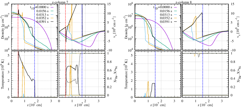
The evidence of tidal detonation is the presence of a reverse shock wave. A reverse shock wave can be easily seen in a -velocity profile.

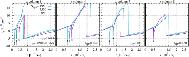
Figure 5 shows the -velocity profiles for -columns 1 - 9 just after pressure waves steepens into shock waves. We can see reverse shock waves of -columns 1 - 7 indicated by arrows. In other words, tidal detonation occurs in -columns 1 - 7, and does not in -columns 8 - 9. The difference between the former and latter -columns is the distances from the IMBH. As seen in Figure 2, the leading part of the WD tends to pass more closely to the IMBH than the trailing part. Therefore, the former -columns are closer to the IMBH (more compressed) than the latter -columns. We expect the materials preceding -column 1 succeed in tidal detonation, and the materials following -column 9 fail in tidal detonation.

Figure 6 shows the profiles of nuclear elements tidal detonation yields in -columns 1, 4, and 7. The nuclear reactions have been already finished in -column 7 at s. Most of materials have been burned by this time. It seems that large amounts of unburned materials are left at cm. However, mass at cm is much smaller than the total mass, since density at cm is much smaller than at cm. The nuclear reactions synthesize % of 56Ni, and leave % of 4He in mass. There are small amounts of Si group elements (28Si, 32S, 36Ar, 40Ca, and 44Ti), and their mass fraction is %. The reason for the small amounts of Si group elements is that detonated materials have high density ( g cm-3). Note that Si group elements are synthesized when a detonation wave proceeds in a region with density of g cm-3.
In the cases of -columns 1 and 4, we have not finished nuclear reactions. These 1D mesh simulations are largely time-consuming. Timestep becomes too small just before the detonation wave reaches the orbital plane () due to nuclear reactions. Here, we make a conjecture about nucleosynthesis in -columns 1 and 4 from the results of -column 7. In the second right panel of Figure 6, we show nuclear components in -column 7 just before a detonation wave reaches the orbital plane. The nuclear components in -columns 1, 4, and 7 are similar just before the detonation waves reach the orbital plane. Therefore, we expect nuclear components in these -columns will be similar when nuclear reactions have finished.
The 1D mesh simulation in the case of -column 7 has been finished in the following reason. Since -column 7 follows -columns 1 and 4, the former is less compressed than the latter. The former density at is smaller. The nuclear reactions in -column 7 are less active than in -columns 1 and 4. Therefore, timestep in the case of -column 7 does not become as small as in the case of -columns 1 and 4.
IV Discussion
We estimate overall nucleosynthesis in our WD TDE model. We also examine 3D effects for the nucleosynthesis.

We consider whether a detonation wave proceeds in the direction of the - plane. Figure 7 shows the position of -column 7 (the white cross) and four arrows from -column 7. These arrows points to four directions on the - plane. Hereafter, we refer to the direction of arrow X as the X-direction. The detonation wave from -column 7 would not proceed in the A-, C-, and D-directions. The -columns in the D-direction have been already detonated. The -columns in the A- and C-directions are detonated simultaneously with -column 7.
The detonation wave from -column 7 would proceed in the B-direction, if no detonation wave is generated from -columns in the B-direction. If detonation waves are generated from -columns in the B-direction, the detonation wave from -column 7 would not proceed in the B-direction. Detonation waves from -columns in the B-direction would be spontaneously generated before the detonation wave from -column 7 reaches these -columns. This is because the speed of the detonation wave ( cm s-1) is much slower than the orbital velocity of the WD ( cm s-1).
Based on the above consideration, we can divide -columns of a WD into two types. The first type is -columns in which tidal detonation arises, such as -columns 1 - 7. The second type is -columns which tidal detonation arising in other -columns reaches. Since tidal detonation succeeds in -columns 7, and fails in -columns 8, we assume that -columns preceding -column 7 are the first type, and that -columns following -column 7 are the second type. Note that leading parts are easier to be detonated than trailing parts, as described in section III.
We discuss about the first type of -columns. All these -columns would be detonated independently of each other. These -columns have mass of . Their nuclear compositions would be similar to those of -columns 1, 4 and 7 (see Figure 6). Then, their nuclear compositions would be 56Ni of and 4He of . There would be small amounts of Si group elements, .
We examine the second type of -columns. They would be detonated by the detonation wave generated in -column 7. From our simulation results, we find the detonation wave traverses these -columns when these -columns have density of g cm-3. Therefore, the detonation wave would yield large amounts of Si group elements in these -columns [12]. Since these -columns have , Si group elements of would be synthesized.
In summary, our WD TDE model would yield 56Ni of and Si group elements of , and leave 4He of . Since parts of them would be swallowed by the IMBH, all of them would not contribute to the luminosity of our WD TDE model. However, we do not investigate the subsequent evolution of the WD TDE. We cannot follow the orbit of the WD debris accurately, since we simplify the IMBH gravity as Newton gravity.
V Summary
We assess whether tidal detonation occurs true in WD TDEs. We choose a He WD with . We need prohibitively large calculation cost to follow tidal detonation of a WD TDE by 3D SPH simulations. Thus, we combine 1D mesh simulations with 3D SPH simulations. For 1D mesh simulations, we develop a method to extract 1D initial conditions from 3D SPH simulation data. Owing to the method, we can follow 1D evolution, not annoyed by 3D effects, such as a tidal field.
We show tidal detonation arises by shock heating. We emphasize it is the first time that numerical simulations demonstrate tidal detonation of a WD triggered by shock heating. For this purpose, we perform severe convergence checks with different of 3D SPH simulations and with different space resolution of 1D mesh simulations. Tidal detonation succeeds in -columns preceding -column 7, and fails in -columns following -column 7. Leading parts are easier to be detonated in the following reason. Leading parts are more compressed by the IMBH than trailing parts, and tend to have higher density. A detonation wave is easier to occur in a higher density region, since nuclear reactions proceed more rapidly.
For -columns preceding -column 7, the detonation waves would yield large amounts of 56Ni, since these -columns have high density, g cm-3. Materials in -columns following -column 7 would be detonated by the detonation wave arising from -column 7. In these -columns, large amounts of Si group elements would be synthesized, since these -columns have density g cm-3 when these -columns receive the detonation wave. Eventually, our WD TDE model would synthesize 56Ni of and Si group elements of , and would leave 4He of . Therefore, the WD TDE could be observed as a luminous thermonuclear transient comparable to type Ia supernovae.
Appendix A Validation of our method
A.1 Comparison between 3D and 1D simulations
In Figure 8, we compare the time evolution of -columns 1, 4, 7, and 8 in the 3D SPH simulation of M with the time evolution of these -columns in the 1D mesh simulation. For this comparison, we turn off nuclear reaction networks in the 1D mesh simulation. We find a good agreement between the 3D SPH and 1D mesh simulation results. Therefore, 3D effects, such as a tidal field, are not significant during this time.

A.2 Comparison between simulations with and without IMBH gravity
We perform 1D mesh simulations, including the IMBH gravity in the -direction. We set separation between the -columns and IMBH to cm (see Figures 1 and 2). Figure 9 shows the -velocity profiles just after pressure waves steepen into shock waves in the cases including the IMBH gravity. Tidal detonation occurs in -columns 1 - 7, and does not in -columns 8 - 9, which is the same as in the cases where we ignore the IMBH gravity. This is because pressure gradients in the -columns are much larger than the IMBH gravity. For example, tidal detonation starts at cm and s in -column 7 (see Figure 4). In that place, the pressure gradient and IMBH gravity are, respectively, cm s-2 (see the curves of s and s of -column 7 panels in Figure 8) and cm s-2.

A.3 Modeling of the WD edge
As seen in the top panel of Figure 3, density structure in the 1D initial condition is extrapolated below g cm-3. This extrapolation does not affect the emergence of tidal detonation, since the tidal detonation emerges at a region reflecting information of 3D SPH simulation. In -column 4, tidal detonation occurs where density is g cm-3. On the other hand, materials in this -column are compressed by a factor of at most during its evolution. Therefore, the tidal detonation emerges at materials whose density is initially g cm-3. In other words, the tidal detonation occurs at a region reflecting 3D SPH simulation results.
As seen in the bottom panel of Figure 3, -velocity structure in the 1D initial condition is slightly oversmoothed at the edge of the -column. We investigate this oversmoothing on the emergence of tidal detonation. Using -velocity structure in the 3D SPH simulation, we extrapolate -velocity structure for -column 4 in two different ways. One is that we set -velocity to zero at cm discontinuously, and the other is that we increase the absolute value of -velocity up to the boundary of the 1D mesh simulation (see the left panel of Figure 10). As seen in the second and third left panels of Figure 10, the modeling of the WD edge affects the edge evolution of -velocity (on the right side of the vertical dotted lines), however does not affects the internal evolution of -velocity which raises pressure waves steepening into shock waves (on the left side of the vertical dotted lines). Finally, we can see in Figure 10 that tidal detonation emerges in both cases of the extrapolated 1D initial conditions, similarly to the original 1D initial conditions. Therefore, the oversmoothing -velocity at the edge of -columns does not affect the emergence of tidal detonation.

A.4 1D resolution check
We perform a convergence check of 1D mesh simulations with different space resolution for -columns 1, 4, 7, and 8. We change the mesh size from cm to cm. Note that the mesh size sufficiently resolves the hotspot size ( cm). Figure 11 shows the time evolution of -velocity profiles with different 1D space resolution. We find a good agreement among the results of different 1D space resolution. We conclude the results about the emergence of tidal detonation are converged among different 1D space resolution.

A.5 3D resolution check
We perform a convergence check of 1D mesh simulations with different in 3D SPH simulations. Note that this is not a convergence check of space resolution in 1D mesh simulations. Figure 12 shows the time evolution of -velocity profiles in -columns 1, 4, 7, and 8 for 3D SPH simulations with M, M, and M. We can see the presence of reverse shock waves in all cases for -columns 1, 4 and 7. On the other hand, for -column 8, a reverse shock wave is present in the M case, and absent in the the M and M cases. Eventually, we find tidal detonation succeeds in the M cases, and fails in the M cases for -column 8.
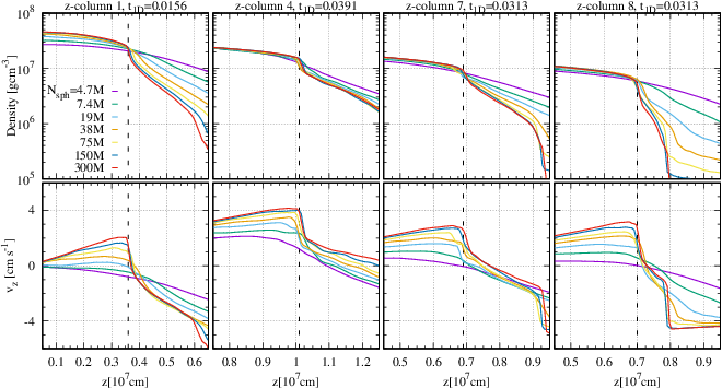
In order to investigate the reason for the failure of tidal detonation in large- cases, we show density and -velocity profiles in these -columns just before shock waves appear in Figure 13. Just after this time, a pressure wave indicated by dashed lines will steepen into a shock wave immediately. Thus, the shock wave will heat the right-side region of the dashed line after this time. In all the -columns, we can see density of the right-side region becomes smaller with increasing if M. Since nuclear reactions proceed more rapidly with density higher, tidal detonation occurs more easily in smaller cases. In all the -columns, density profiles in the M cases are the same. Therefore, the 1D mesh simulations are converged in the range from M to M. In other words, tidal detonation fails in -column 8, and tidal detonation will succeed in -columns 1, 4 and 7 even if becomes infinite.
The reason for the unconvergence in the M cases is that initial conditions of 1D mesh simulations in the M cases are not converged, since the results of 3D SPH simulations are not converged especially at the WD edge. Figure 14 shows the initial conditions of -column 8 in 3D SPH simulations with M to M. At the edge of the -column, density decreases with increasing. Generally, SPH methods can capture edge structure sharply with increasing, since SPH kernel length becomes smaller with increasing. Therefore, density at the edge is overestimated, and tidal detonation occurs falsely for smaller- cases.

References
- [1] Auchettl, K., Guillochon, J., & Ramirez-Ruiz, E. 2017, ApJ, 838, 149
- [2] Balsara, D. S. 1995, Journal of Computational Physics, 121, 357
- [3] Brassart, M., & Luminet, J.-P. 2008, A&A, 481, 259
- [4] Cheng, R. M., & Bogdanović, T. 2014, Phys. Rev. D, 90, 064020
- [5] Clausen, D., & Eracleous, M. 2011, ApJ, 726, 34
- [6] Colella, P., & Woodward, P. R. 1984, Journal of Computational Physics, 54, 174
- [7] Dehnen, W., & Aly, H. 2012, MNRAS, 425, 1068
- [8] East, W. E. 2014, ApJ, 795, 135
- [9] Fryxell, B., Olson, K., Ricker, P., et al. 2000, ApJS, 131, 273
- [10] —. 2010, FLASH: Adaptive Mesh Hydrodynamics Code for Modeling Astrophysical Thermonuclear Flashes, Astrophysics Source Code Library, ascl:1010.082
- [11] Haas, R., Shcherbakov, R. V., Bode, T., & Laguna, P. 2012, ApJ, 749, 117
- [12] Holcomb, C., Guillochon, J., De Colle, F., & Ramirez-Ruiz, E. 2013, ApJ, 771, 14
- [13] Ioka, K., Hotokezaka, K., & Piran, T. 2016, ApJ, 833, 110
- [14] Iwasawa, M., Tanikawa, A., Hosono, N., et al. 2016, PASJ, 68, 54
- [15] Kawana, K., Tanikawa, A., & Yoshida, N. 2017, ArXiv e-prints, arXiv:1705.05526
- [16] Kobayashi, S., Laguna, P., Phinney, E. S., & Mészáros, P. 2004, ApJ, 615, 855
- [17] Komossa, S. 2015, Journal of High Energy Astrophysics, 7, 148
- [18] Krolik, J. H., & Piran, T. 2011, ApJ, 743, 134
- [19] —. 2012, ApJ, 749, 92
- [20] Law-Smith, J., MacLeod, M., Guillochon, J., Macias, P., & Ramirez-Ruiz, E. 2017, ApJ, 841, 132
- [21] Luminet, J.-P., & Pichon, B. 1989, A&A, 209, 103
- [22] MacLeod, M., Goldstein, J., Ramirez-Ruiz, E., Guillochon, J., & Samsing, J. 2014, ApJ, 794, 9
- [23] MacLeod, M., Guillochon, J., Ramirez-Ruiz, E., Kasen, D., & Rosswog, S. 2016, ApJ, 819, 3
- [24] Monaghan, J. J. 1997, Journal of Computational Physics, 136, 298
- [25] Morris, J. P., & Monaghan, J. J. 1997, Journal of Computational Physics, 136, 41
- [26] Parsons, S. G., Gänsicke, B. T., Marsh, T. R., et al. 2017, MNRAS, 470, 4473
- [27] Price, D. J., & Monaghan, J. J. 2007, MNRAS, 374, 1347
- [28] Rosswog, S., Ramirez-Ruiz, E., & Hix, W. R. 2009, ApJ, 695, 404
- [29] Rosswog, S., Ramirez-Ruiz, E., Hix, W. R., & Dan, M. 2008, Computer Physics Communications, 179, 184
- [30] Shiokawa, H., Krolik, J. H., Cheng, R. M., Piran, T., & Noble, S. C. 2015, ApJ, 804, 85
- [31] Stone, N., Sari, R., & Loeb, A. 2013, MNRAS, 435, 1809
- [32] Stone, N. C., Kesden, M., Cheng, R. M., & van Velzen, S. 2018, ArXiv e-prints, arXiv:1801.10180
- [33] Tanikawa, A., Nakasato, N., Sato, Y., et al. 2015, ApJ, 807, 40
- [34] Tanikawa, A., Sato, Y., Nomoto, K., et al. 2017, ApJ, 839, 81
- [35] Tanikawa, A., Yoshikawa, K., Nitadori, K., & Okamoto, T. 2013, New A, 19, 74
- [36] Tanikawa, A., Yoshikawa, K., Okamoto, T., & Nitadori, K. 2012, New A, 17, 82
- [37] Tchekhovskoy, A., Metzger, B. D., Giannios, D., & Kelley, L. Z. 2014, MNRAS, 437, 2744
- [38] Tejeda, E., & Rosswog, S. 2013, MNRAS, 433, 1930
- [39] Timmes, F. X., & Swesty, F. D. 2000, ApJS, 126, 501
- [40] van Velzen, S., Frail, D. A., Körding, E., & Falcke, H. 2013, A&A, 552, A5
- [41] van Velzen, S., Körding, E., & Falcke, H. 2011, MNRAS, 417, L51
- [42] Wendland, H. 1995, Advances in Computational Mathematics, 4, 389
- [43] Wilson, J. R., & Mathews, G. J. 2004, ApJ, 610, 368
- [44] Zalamea, I., Menou, K., & Beloborodov, A. M. 2010, MNRAS, 409, L25