Merger and reconnection of Weibel separated relativistic electron beam
Abstract
The relativistic electron beam (REB) propagation in a plasma is fraught with beam plasma instabilities. The prominent amongst them being the collisionless Weibel destabilization which spatially separates the forward propagating REB and the return shielding currents. This results in the formation of REB current filaments which are typically of the size of electron skin depth during the linear stage of the instability. It has been observed that in the nonlinear stage the filaments size increases as they merge with each other. With the help of 2-D PIC simulations in the plane perpendicular to the REB propagation, it is shown that these mergers occur in two distinct nonlinear phases. In the first phase, the total magnetic energy increases. Subsequently, however, during the second phase, one observes a reduction in magnetic energy. It is shown that the transition from one nonlinear regime to another occurs when the typical current associated with individual filaments hits the Alfvén threshold. In the second nonlinear regime, therefore, the filaments can no longer permit any increase in current. Magnetic reconnection events then dissipate the excess current (and its associated magnetic energy) that would result from a merger process leading to the generation of energetic electrons jets in the perpendicular plane. At later times when there are only few filaments left the individual reconnection events can be clearly identified. It is observed that in between such events the magnetic energy remains constant and shows a sudden drop as and when two filaments merge. The electron jets released in these reconnection events are thus responsible for the transverse heating which has been mentioned in some previous studies [Honda et al. Phys. Plasmas 7, 1302 (2000)].
I INTRODUCTION
The existence and impact of the magnetic field in astrophysical events have continued to excite researchers, positing interesting issues pertaining to plasma physics. With the advent of high intensity lasers, it has been possible to make interesting observations on the dynamical evolution of magnetic field in laboratory experiments on laser matter interaction [1, 2, 3, 4, 5]. The intense lasers ionize the matter into plasma state and dump their energy into the lighter electron species, generating relativistic electron beam (REB) [6, 7, 8] in the medium. Though the propagation of relativistic electron beam with current more than Alfvén current limit i.e. , where , is velocity of beam and is relativistic Lorentz factor, is not permitted in the vacuum ( as the associated magnetic fields are large enough to totally curve back the trajectories of the electrons). In plasma medium, this is achieved as the current due to REBs are compensated by the return shielding current in the opposite direction provided by the electrons of the background plasma medium. The two currents initially overlap spatially, resulting in zero net currents and so no magnetic field is present initially. The combination of forward and reverse shielding current is, however, susceptible to several micro-instabilities. A leading instability in the relativistic regime is the filamentation instability [9]. It is often also termed as the Weibel instability [10]. The filamentation/ Weibel instability creates spatial separation of the forward and reverse shielding currents. The current separation leads to the generation of the magnetic field at the expense of the kinetic energy of the beam and plasma particles. The typical scale length at which the Weibel separation has the maximum growth rate is at the electron skin depth scale . The Weibel separation, thus, leads to the formation of REB current filaments of the size of electron skin depth scale and is responsible for the growth of the magnetic energy in the system. The dynamics, long term evolution and energetics associated with the Weibel instability of current filaments are of central importance in many contexts. For instance, in fast ignition concept of fusion, the energetic REB is expected to create an ignition spark at the compressed core of the target for which it has to traverse the lower density plasma corona [11, 12, 14, 13, 15] and dump its energy at the central dense core of the target. This requires a complete understanding of REB propagation in the plasma medium. In astrophysical scenario, the generation of cosmological magnetic field and relativistic collisionless shock formation in gamma ray bursts have often been attributed to the collisionless Weibel instability [16, 17, 18, 19, 20]. The formation of collisionless shock and it’s behavior depends on long term evolution and dynamics of the magnetic field generated through Weibel destabilization process.
The growth of magnetic field through the Weibel destabilization process influences the propagation of REB filaments. In this nonlinear stage, the current filaments are observed to coalesce and form the larger structure. There are indications from previous studies [21] that at the early nonlinear stage of evolution there is a growth of magnetic field energy. Subsequently, however, the magnetic energy shows decay. The physical mechanism for the observed decay of magnetic field at later stages is the focus of the present studies. There are suggestions that the merging process of super Alfvénic currents carrying filaments leads to the decay of magnetic energy [21]. On the other hand, the mechanism of magnetic reconnection which rearranges the magnetic topology in plasma is also invoked which converts the magnetic energy to kinetic energy of the particles. This can result in thermal particles or the particles may even get accelerated [22, 23] by the reconnection process. The merger of current filaments leading to point formation where reconnection happens has been shown in the schematic diagram Fig. 1.
In this work, we have studied the linear and non-linear stage of Weibel instability in detail with the help of 2-D Particle - In- Cell (PIC) simulation. The 2-D plane of simulation is perpendicular to the current flow direction. The initial condition is chosen as two overlapping oppositely propagating electron currents. The development of the instability, the characteristic features during nonlinear phase etc., are studied in detail.
The paper has been organized as follows. The simulation set up has been discussed in section II. The observations corresponding to the linear phase of instability is presented in section III. The nonlinear phase of the instability covered in section IV. Section V provides for the summary and the discussion.
II SIMULATION SET-UP
We employ OSIRIS2.0 [24, 25] Particle - In - Cell (PIC) code to study the evolution of the two counterstreaming electron current flows in a 2-D plane perpendicular to the current flow direction of . We have considered the ion response to be negligible and treated them as merely providing a stationary neutralizing background. Thus the dynamics is governed by electron species alone. However, this would not be applicable at longer times where ion response may become important and introduce new features.
The boundary conditions are chosen to be periodic for both the electromagnetic field and the charged particles in all direction. We choose the area of the simulation box as corresponding to cells. The time step is chosen to be where and is the total electron density which is the sum of beam and the plasma electrons denoted by suffix and respectively. The total number of electrons and ions per cell in the simulations are chosen to be each. The quasi neutrality is maintained in the system by choosing equal number of electrons and ions. The velocity of beam electrons and the cold plasma electrons are chosen to satisfy current neutrality condition. The uniform plasma density is taken as and the ratio of electron beam density to background electron density has been taken as() is the simulations presented here. The fields are normalized by . The evolution of field energy normalized by is averaged over the simulation box. We have carried simulations for the choice of cold as well as finite temperature beams. Several choices of beam temperature were considered.
III LINEAR STAGE OF INSTABILITY
The charge neutrality and the current balance condition, chosen initially ensures that there are no electric and magnetic fields associated with the system and equilibrium conditions are satisfied. We observe a development of magnetic field structures of the typical size of electron skin depth with time. This can be seen in Fig. 2 where the contours of the transverse magnetic field have been shown in the 2D plane. The development of this magnetic field can be understood as arising due to the spatial separation of forward and return currents through Weibel destabilization process. The growth of transverse magnetic field energy with time has been shown in Fig.3 for the two cases with following parameters: (I) and (II) , , . The initial linear phase of growth is depicted by the straight line region in the log linear plot. A comparison with the analytically estimated maximum growth rate for the two cases has been provided by the dashed line drawn alongside.
The growth rate for case (I) with the growth rate obtained from the simulation by measuring the half of the slope of the magnetic energy evolution in Fig. 3 is and it compares well with the analytical value of ([26]). Similarly for case (II) when the beam temperature is finite the growth rate of from simulation agrees well with the analytical estimate obtained from kinetic calculations for these parameters of ([27]). It should be noted that this is consistent with the well known characteristic feature of the reduction in Weibel growth rate by increasing beam temperature. After the linear phase of growth, it can be observed from Fig. 3 that when the normalized magnetic energy becomes of the order of unity the increase in magnetic energy considerably slows down. This reflects the onset of the nonlinear regime. We discuss the nonlinear regime of the instability in the next section in detail.
IV NONLINEAR STAGE OF INSTABILITY
When the Weibel separated magnetic fields acquire significant magnitude, they start influencing the dynamics of beam and plasma particles. This backreaction signifies the onset of nonlinear regime. The plot of the magnetic energy growth in Fig. 3 clearly, shows that at around (cold beam-plasma system) the system enters the nonlinear phase. The characteristics behaviour in the nonlinear regime has been described in the subsections below:
IV.1 Current filaments
In the non-linear stage of WI, the current filaments, flowing in the same direction, merge with each other with time and organize as bigger size filaments. During the initial nonlinear stage magnetic field energy keeps growing, albeit at a rate which is much slower than the linear growth rate and then saturates (Fig. 4). Subsequently, the magnetic field energy decreases as can be observed from the plot of Fig. 4.
A rough estimate of the saturated magnetic field can be made by the following simple consideration. The spatial profile of the magnetic field in the current filament is mimicked as a sinusoidal function with representation the inverse of the filament size. The amplitude of the magnetic field is which in the nonlinear regime significantly deflects the trajectories of the electrons. The transverse motion of an electron in the plane of the magnetic field is then given by
| (1) |
The bounce frequency of a magnetically trapped electron is thus
| (2) |
the saturation would occur when the typical bounce frequency becomes equal to the maximum linear growth rate of instability. Therefore, the saturated magnetic field can be estimated by comparing the linear growth of filamentation instability to the bounce frequency (). In case of mono-energetic distribution function, the saturated magnetic field is
| (3) |
The estimate provided by the eq.( 3) compares well with the observed saturated value of the magnetic field which is equal to 0.1.
IV.2 Alfvén limited filaments
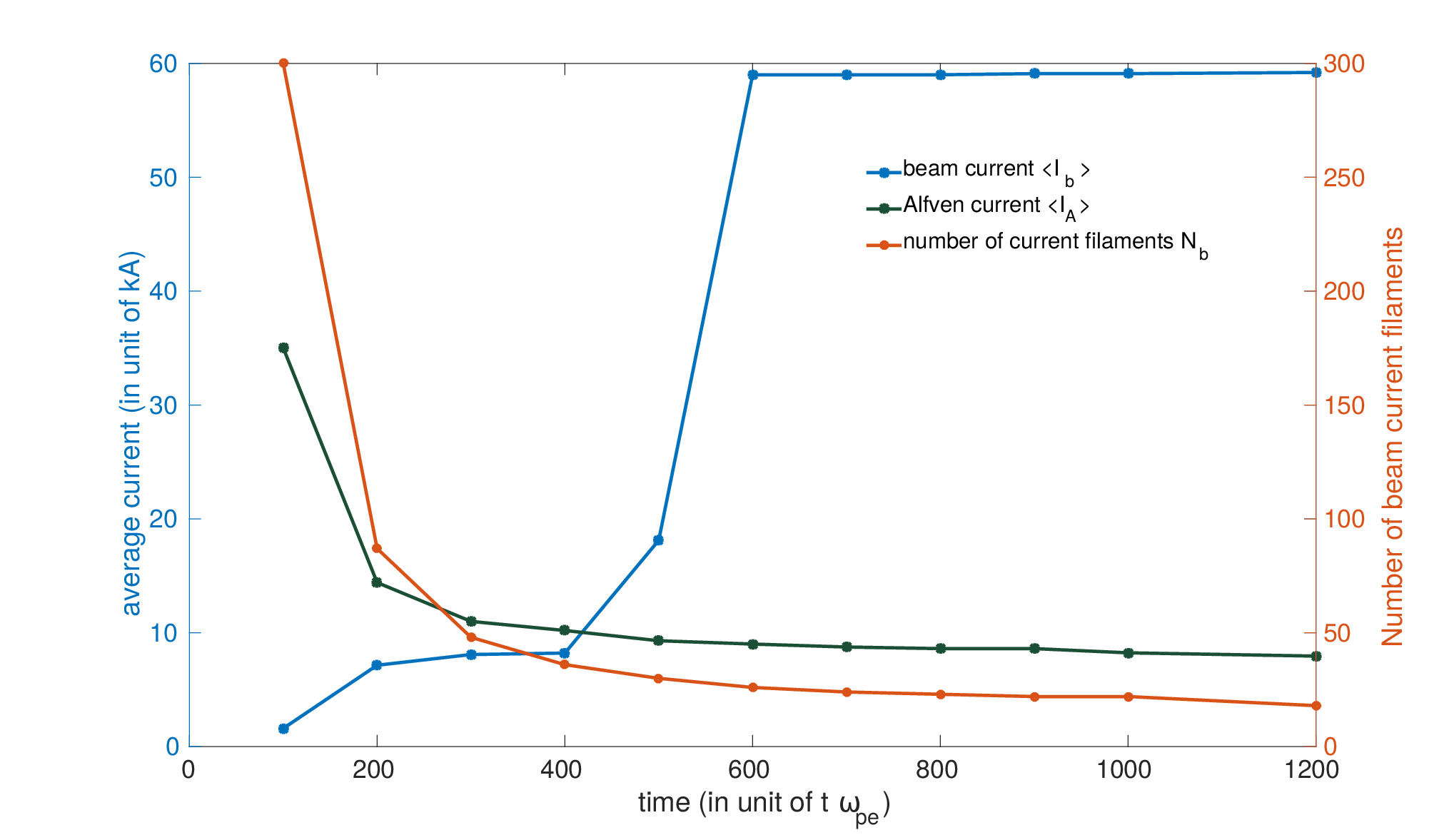
The process of merging of like current filaments can be seen from the plots of temporal evolution of the current densities shown in Fig. 5. The current in the filament is essentially due to the beam electrons as illustrated in Fig. 5. The current in the filament, however, should not exceed the Alfvén limit. The value of the Alfvén limit for our simulations is . In Fig. 6, we show the evolution of the beam current and the number of filaments in the simulation box.
The number of filaments keeps dropping slowly, however, the average beam current in the filament keeps increasing. Since the beam particles convert the partial kinetic energy into magnetic field energy and slow down, the Alfvén current limit drops with time and finally saturates. The magnetic field keep on increasing until the average beam current lower than Alfvén current limit and at particular time, the average beam current cross the Alfvén current limit. This is also the time after which there is no increase in the magnetic energy of the system. After the saturation of instability, the magnetic field energy ( zoomed for better view) starts decaying as shown in Fig. 4. In fact, one observes that the magnetic energy reduces after this time. This decay in the magnetic field energy can be understood on the basis of magnetic reconnection phenomena.
IV.3 Electron jet formation
At later times when only few filaments are left in the system, we can track each of the filaments individually. We choose two such filaments which are about to converge and observe their behaviour as they coalesce with each other in Fig. 7. The figures show the formation of electron jets in the plane as the two structures merge with each other.
The structures basically follow the EMHD[28, 29, 30] dynamics. Thus as the filaments come near each other they carry the with them. The filament scales being longer than electron skin depth, the magnetic field is essentially carried by the electron flow in the plane. However, when the filaments hit each other the magnetic fields get compressed against each other and scale sizes smaller than electron skin depth are formed. The collisionless inertia driven reconnection takes place and generating energetic electron jets in the direction orthogonal to the direction at which the filaments approach each other.
There is a change in magnetic field topology and accelerated electrons are observed. This is responsible for the reduction in magnetic field energy. In fact, each of the sudden drops in magnetic field energy can be times with such reconnection events in the simulation. The increase in the perpendicular energy of the electrons has been shown in Fig. 4.
It is interesting to note that nature tries to use ingenious and rapid techniques to relax a highly asymmetric system such as the one with inter-penetrating electron current flows along . The system being collisionless it would not have been possible to convert (kinetic energy parallel to axis to ). The magnetic field provides an intermediary role to aid this process and symmetrize the system.
V CONCLUSIONS
In the present article, we have studied theoretically as well as numerically (PIC simulation) the Weibel instability in beam plasma system. We have shown that the linear stage of Weibel instability shows good agreement with PIC simulation results. In the non-linear stage, the current filaments having the flow in the same direction merge into each other. There is a rearrangement of the magnetic field lines through reconnection process leading to energetic electron jets in the plane. This has been clearly observed in the simulation. So ultimately the parallel flow energy gets converted into the perpendicular electron energy. Basically, the excitation of the instability and the nonlinear evolution tries to relax the configuration towards an isotropic configuration rapidly in a collsionless system.
References
- [1] J. A. Stamper, K. Papadapoulos, R. N. Sudan, E. McLean, S. Dean, and J. Dawson. Phys. Rev. Lett. 26, 1012 (1971).
- [2] Shinsuke Fujioka, Zhe Zhang, Kazuhiro Ishihara, Keisuke Shigemori, Youichiro Hironaka, Tomoyuki Johzaki, Atsushi Sunahara, Naoji Yamamoto, Hideki Nakashima, Tsuguhiro Watanabe, Hiroyuki Shiraga, Hiroaki Nishimura and Hiroshi Azechi. Scientific Reports 3, 1170 (2013).
- [3] Sudipta Mondal, V. Narayanan, Wen Jun Ding, Amit D. Lad, Biao Hao, Saima Ahmad, Wei Min Wang, Zheng Ming Sheng, Sudip Sengupta, Predhiman Kaw, Amita Das and G. Ravindra Kumar, Proceedings of the National Academy of Sciences 109, 8011 (2012).
- [4] A. Flacco, J. Vieira, A. Lifschitz, F. Sylla, S. Kahaly, M. Veltcheva, L. O. Silva and V. Malka Nature Physics 11, 409 (2015).
- [5] Gourab Chatterjee, Kevin M. Schoeffler, Prashant Kumar Singh, Amitava Adak, Amit D. Lad, Sudip Sengupta, Predhiman Kaw, Luis O. Silva, Amita Das and G. Ravindra Kumar, Nature Communications 8, 15970 (2017).
- [6] A. Modena, Nature 377, 1 (1995).
- [7] G. Malka and J. L. Miquel, Phys. Rev. Lett. 77, 75 (1996).
- [8] K. B. Wharton, S. P. Hatchett, S. C. Wilks, M. H. Key, J. D. Moody, V. Yanovsky, A. A. Offenberger, B. A. Hammel, M. D. Perry, and C. Joshi, Phys. Rev. Lett. 81, 822 (1998).
- [9] Burton D. Fried, Phys. Fluids 2, 337 (1959).
- [10] Erich S. Weibel, Phys. Rev. Lett. 2, 83 (1959).
- [11] M. Tabak et al., Phys. Plasmas 12, 5 (2005).
- [12] S. Atzeni and J. Meyer-ter-Vehn, The Physics of Inertial Fusion, Oxford University Press (2004).
- [13] Jeremy Martin Hill et al., Phys. Plasmas 12, 082304 (2005).
- [14] T. Taguchi et al., Phys. Rev. Lett. 86, 5055 (2001).
- [15] M. Honda et al., Phys. Rev. Lett. 85, 2128 (2000).
- [16] M. Lazar, R. Schlickeiser, R. Wielebinski and S. Poedts, Astrophys. J. 693, 1133 (2009).
- [17] C. M. Huntington et al. , Nat. Phys. 11, 173 (2015).
- [18] M. V. Medvedev and A. Loeb, Astrophys. J. 526, 697 (1999).
- [19] M. V. Medvedev et al., Astrophys. J. 618, L75 (2005).
- [20] L. O. Silva et al., Phys. Plasmas 9, 2458 (2002).
- [21] Oleg Polomarov, Igor Kaganovich, and Gennady Shvets, Phys. Rev. Lett. 101, 175001 (2008).
- [22] F. Califano et al., Phys. Rev. Lett. 86, 5293 (2001).
- [23] S. Zenitani and M. Hesse, Phys. Plasmas 9, 022101 (2008).
- [24] R. A. Fonseca, et al., OSIRIS: A Three-Dimensional, Fully Relativistic Particle in Cell Code for Modeling Plasma Based Accelerators (Springer Berlin Heidelberg, Berlin, Heidelberg, 2002), pp. 342.
- [25] R. A. Fonseca, et al., Plasma Physics and Controlled Fusion 50, 124034 (2008).
- [26] B. B. Godfrey, W. R. Shanahan, and L. E. Thode, Phys. Fluids 18, 346 (1975).
- [27] Biao Hao, W.-J. Ding, Z.-M. Sheng, C. Ren and J. Zhang, Phys. Rev. E., 80, 0066402 (2009).
- [28] Kingsep, A. S., K. V. Chukbar, and V. V. Yan’kov, in Reviews of Plasma Physics, 16, edited by B. B. Kadomtsev, pp. 243–291, Consultants Bureau, New York, 1990.
- [29] R. L. Stenzel, J. M. Urrutia, M. C. Griskey, and K. D. Strohmaier Earth Planets Space, 53, 553–560, (2001).
- [30] Amita Das, Plasma Phys. Control. Fusion 41, A531 (1999 ).