CObRaSO: Compliant Omni-Direction Bendable Hybrid Rigid and Soft OmniCrawler Module
Abstract
This paper presents a novel design of an Omnidirectional bendable Omnicrawler module- CObRaSO. Along with the longitudinal crawling and sideways rolling motion, the performance of the OmniCrawler is further enhanced by the introduction of Omnidirectional bending within the module, which is the key contribution of this paper. The Omnidirectional bending is achieved by an arrangement of two independent 1-DOF joints aligned at w.r.t each other. The unique characteristic of this module is its ability to crawl in Omnidirectionally bent configuration which is achieved by a novel design of a 2-DOF roller chain and a backbone of a hybrid structure of a soft-rigid material. This hybrid structure provides compliant pathways for the lug-chain assembly to passively conform with the orientation of the module and crawl in Omnidirectional bent configuration, which makes this module one of its kind. Furthermore, we show that the unique modular design of CObRaSO unveils its versatility by achieving active compliance on an uneven surface, demonstrating its applications in different robotic platforms (an in-pipeline robot, Quadruped and snake robot) and exhibiting hybrid locomotion modes in various configurations of the robots. The mechanism and mobility characteristics of the proposed module have been verified with the aid of simulations and experiments on real robot prototype.
I INTRODUCTION
Mobile robots capable of traversing unstructured environment are highly useful for inspection, exploration of the unknown and risky areas as well as for Urban search and rescue (USAR) operations. High level of adaptability on uneven rough terrain and efficient maneuvering in confined spaces are the desired key functionalities of these robots. The performance of a robot locomotion is determined by the trafficability, maneuverability, and terrainability [1], and these pose important challenges in the design of search and rescue robots.


The impressive capabilities of wheeled, legged and tracked based mobile robots on the rugged surface are well documented in literature [17]. Land-based robots are generally based on wheeled locomotion, due to their fast rolling and energy efficient motion on hard-flat surface [2]. Legged robots possess good adaptability by varying the effective length and orientation of the legs which facilitates them to navigate in uneven natural terrains and overcome obstacles much better than wheeled robots [2]. Continuous Track robots are favorable due to their added advantages of crawling over holes and ability to smooth out the path, putting low pressure on terrain and providing large ground contact surface and traction [3]. Moreover, for high-risk missions such as military applications, where robots are required to have good traction and stability for the successful mission, tracked robots performs difficult locomotion and dexterous manipulation tasks [19]. These potential advantages of each locomotion mode have led to the development of a number of robots with hybrid locomotion modes such as wheel-leg, leg-track, wheel-track, and wheel-leg-track. Robots exhibiting hybrid locomotion modes take the potential advantages of each one while attempting to avoid their drawbacks. These robots exploit the most appropriate locomotion mode for the prevailing conditions in the environment. Francois et. al. [4] developed a multimodal wheel-leg-track locomotion robotic platform- AZIMUT, where each of the 4 independent articulated modules can generate a variety of motions such as omnidirectional motion, climbing obstacles and stairs. Zhu et. al. [5] also proposed a hybrid leg-wheel-track robot, which consists of a robot body with four driving mechanisms, four independent track devices, two supporting legs and one wheel lifting mechanism. Similarly, there are several other hybrid robots such as Transformable wheel-track robot[6], Tri-Wheel [7], TITAN-X[20].
The state-of-the-art hybrid robots discussed above incorporate conventional tank-like crawler modules which can only support longitudinal (forward and backward) crawling motion. The motion capabilities and terrain adaptability of these robots on an uneven surface have been improved with the development of articulated multi-tracked robots by linking several passive or active tracked modules [8], [12]. These robots require individual actuators for each of its articulated crawler module, which leads to an increase in size and weight of the robot. This further attenuates their capability to realize easy and efficient turning motion in constrained spaces. This paper proposes a novel design of an Omni-directional bendable OmniCrawler module- CObrRaSO, which incorporates several cascaded sub-modules with a pair of the chain going over the entire length of the module. A couple of sprocket-chain pairs is driven by a single actuator and therefore, the compact structure of the module facilitates steering and turning motion in constrained spaces with minimum actuators.
In our previous work, we have designed an OmniCrawler module with 1-DOF active compliant joints and the motion capabilities of the mechanism were demonstrated with its applications in an in-pipe climbing robot (COCrIP) [10]. The objective of the present work is to extend the capabilities and scope of applications of the OmniCrawler module in several mobile robots platforms. The Omnidirectional joints in CObrRaSO achieve compliance in the desired direction, which is the key contribution of this paper. This Omnidirectional bending capability enables it to exhibit different locomotion modes- wheel, leg and crawler in different robotic platforms. Its design is based on an OmniCrawler module, inspired by [9]. The Omnidirectional bending is characterized by the novel design of a 2-DOF compliant roller chain and a hybrid structure of soft-rigid materials. The unique design of the lugs and the ability of the chain to conform with the bent chassis of the module enables crawling motion even in the bent configuration. This property of achieving Omnidirectional bending while crawling makes this module one of its kind. Therefore, the robot can achieve turning and steering motion using a single actuator (which drives both the lug-chain assemblies). The motion of lug-chain assembly over the surface of the bent module further enables it to exhibit surface actuation property, which helps in obstacle aided motion. The surface actuation robot developed previously by McKenna [13] has demonstrated crawling motion only in the straight configuration since the toroidal skin used for locomotion seems to become loose while bending and does not maintain enough tension for crawling in a bent configuration.
The objective of this research and key contributions of this paper are summarized as below:
1. A seminal concept of Omnidirectional bending in an OmniCrawler module is introduced. This is realized using a hybrid combination of soft and rigid materials and a unique design of a 2-DOF roller chain.
2. The versatility of its modular design provides potential advantages of attaining various configurations and facilitates its integration with various robotic platforms, such as in-pipe climbing robot, Quadruped, snake robot, robotic manipulator, gripper and legged robots.
3. The Omnidirectional bending enhances its capabilities to exhibit various locomotion modes in various robots. For instance, with the hybrid locomotion modes, the Quadruped can navigate through tight spaces by switching its configuration between legged and crawling locomotion modes.
II Mechanical design Overview

II-A Omnidirectional bendable OmniCrawler Module
The OmniCrawler module consists of a couple of chain-sprocket power transmission pairs on either side of the Sagittal plane of the module. Two longitudinal series of lugs resting on the chain links through attachments give a circular cross-section to the module and the ends of the module attain hemispherical shape. These two lug-chain-sprocket assemblies are driven by a micro-motor through a spur-gear train with a gear ratio of 1.25:1 (r:1). Torque driving the each of the two lug-chain assemblies can be calculated as follows.
| (1) | ||||
where is the rated torque of the geared driving motor.
| Quantity | Symbol | Values |
|---|---|---|
| mass of module | 0.320kg | |
| length of module | 0.24m | |
| Driving motors saturation torque | 1.5Nm | |
| Joint motors saturation torque | 1.5Nm | |
| Diameter of circular plate | 0.040m | |
| Joint limit of omnidirectional joint | , | |
| Diameter of module | 0.060m | |
| Thickness of silicone rubber | 0.004m | |
| Width of silicone rubber | 0.010m | |
| Length of silicone rubber | 0.022m | |
| Length of lug | 0.010m | |
| Height of lug | 0.035m | |
| Separation between plates | 0.025m |
II-A1 Omnidirectional bending
The exploded CAD view of the module demonstrating the arrangement of chains, lugs, motor mounts, bearings, gears, screw driven linear actuators and chassis in the module, is shown in Fig. 2. The chassis of the module consists of 3 circular plates which hold an arrangement of 2 independent 1-DOF joints aligned at with respect to each other. The Omnidirectional bending is realized by controlling the rotation of these joints about Pitch and Yaw axes, as shown in Fig.1c.
II-A2 An arrangement of two independent 1-DOF joints aligned at 90∘
An assembly of Omnidirectional joint consists of two independent 1-DOF joints aligned at 90∘ w.r.t each other at an offset distance between them. The module consists of two such assemblies of joints held together by 3 circular plates. The central plate (Plate No.2) holds 2 motors aligned along Y and Z axes; and each of the other two circular plates holds one motor aligned individually along Y (Plate No.3) or Z (Plate No.1) axis, respectively. The arrangement of these joints in between the circular plates is shown in CAD model in Fig. 2. The width and diameter of each of these 3 circular plates have been determined by the design constraints posed by the size of actuators incorporated inside them.
II-A3 2-DOF Chain design
In order to comply and crawl with the bent chassis in an Omnidirectional bent configuration of the module, a 2-DOF roller chain has been designed which can rotate about two perpendicular axes and this aids bending about Pitch as well as Yaw axis, which is a unique characteristic of this roller chain. Each chain link comprises of grooves on both of its sides and the successive links are coupled along these grooves. While the rotation of successive chain links about the roller provides the rotation about the Pitch axis, the relative rotation between two links along the grooves facilitates rotation about Yaw axis, as shown in Fig. 3a, 3b. This makes the design and functionality of this chain very unique, and it attains any orientation in the 3-D plane as shown in Fig. 3c.


II-A4 Lug-Chain assembly
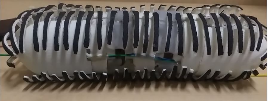
The OmniCrawler module possesses an extra degree of freedom, i.e sideways rolling along the Y axis and this enables it to exhibit holonomic motion, which is characterized by the design and arrangement of two identical series of lug-chain assembly. The semi-circular shape of the lugs provides the circular cross-section to the module and the module’s ends attain hemispherical shape, as shown in module’s prototype in Fig.1. The lugs are connected to the chain links via a fastener (Fig. 4a) and the unique design of chain enables the lug-chain assembly to passively conform with the bent configuration of the module while driving.


The design and arrangement of lugs are determined by the joint angles limit of the module and the diameter of the circular plates. The length of lugs () is optimized to cover the maximum surface of the module. Additionally, the height of lug () is determined by the passage of the lug-chain assembly provided by 3 circular plates and material property of silicone rubber embedded between them. To avoid inter-lug interference when the module bends about Pitch axis () and Yaw axis (), the inter-lug separation () is determined by the geometric constraints of the lug and the joint angles limit (), as follows.
| (2) | ||||
For the design parameters listed in Table I, , , therefore, .
The lugs have been designed with tapered ends (Fig. 4a) in order to prevent inter-lug interference at the hemispherical ends of the module. Furthermore, the separation between two parallel series of lug-chain assemblies, going through the circular plates passage, is kept as small as possible so that the lugs cover the entire cross-section of the module and lugs provide maximum contact with the surface/terrain while crawling.
II-A5 Silicone Rubber for guiding channel during Omnidirectional bending


The guiding channel for the two series of lug-chain assembly is provided by 3 circular plates. However, the offset distance in the Omnidirectional joint assembly (incorporated in between these plates) introduces a discontinuity in this pathway (guided channel). As a result of this non-uniform path, the lug-chain assembly tends to get stuck at the edges of the circular plates, which may hinder further movement of chains thereby, leading to either breakage of lug-chain assembly or excessive torque requirement to overcome those edges. Therefore, soft silicone material of geometry shown in Fig. 5a is embedded in between the circular plates to provide continuity in the pathway of lug-chain assembly in any desired directional bending. Additionally, it prevents the robot from mechanical damage on the rugged terrain by distributing the transferred force (between the terrain and robot) evenly over the contact surface. The support provided by the silicone rubber for the chain further prevents the lug-chain assembly from sagging inwards while crawling on the jagged terrain. It also absorbs much of the energy arising from the collision with such terrain thereby, making the module more robust to a highly unstructured surface.
The Silicone rubber material has been prepared by mixing an equal ratio of two parts (A & B) of Ecoflex 00-30, Smooth-On Inc. with a 100 modulus of 69 kPa. The specifications of the mold are determined by following 4 parameters. 1) Characteristics of the silicone rubber, 2) Joint angle limits (,), 3) Dimensions of lug-chain assembly, 4) Shape of edges of the circular plates, as it needs to provide a uniform pathway from soft surface to rigid circular plates. Experimentally selected values of height () and width () are listed in Table I.


By embedding the soft silicone rubber in between the plates, deformation of silicone is geometrically constrained by the orientation of the circular plates, as shown in FIG. 5b. When the module bends about Pitch axis (Fig. 6a), the passive conformation of the silicone rubber with the configuration of the module chassis results in elongation from , to , and bending from , to , . Similarly, when module bends about Yaw axis (Fig. 6b), rubber elongates from , to , and bends from , to , . Since the specified shrinkage of silicone material is inch/inch, it is assumed to be incompressible and therefore, it bends and bulges out instead of compression. This elongation and bending of the rubber influence the motion behavior of the lug-chain assembly along the guided channel provided by it. While the elongation results in a reduction in the cross-sectional area of the channel (x), which produces more resistance in motion along this path, bending leads to bulging out of rubber which further impedes the motion of the lugs. To determine an optimal trade-off between reduction in cross-sectional area during extension and bulging out during bending, the characteristics of the silicone material were estimated by performing tensile testing on 3 specimens of Silicone rubber with variable thickness values of =2,4 and 6. The silicone rubber is mathematically modeled as a neo-Hookean material as it exhibits more or less linear or even flattening force-elongation behavior in uniaxial tension, for a finite strain range [11]. As the sample is pulled uniaxially, the strain in the height () and the length () directions are the same. Since, the thin rubber reached breakpoint with less force, based on experimental results, we selected silicone with thickness and the rubber was embedded in a pre-extended form which ensures that it does not bulge out when the path length decreases.
II-B Tensioner to adjust chain tension in the bent configuration of the module
The novelty of this module is its ability to crawl in the bent configuration, which is characterized by the unique design of a 2-DOF roller chain. When the module bends, the lug-chain assembly aligns itself with the bent chassis along the path provided by the hybrid structure of rigid (circular plates)-soft (silicone) material. Bending about different axes results in the variation in the path length of the chain-lug assembly, as discussed below.


1) Bending about Pitch axis () The bending of module about Pitch axis (Fig. 7a) results in an increase and decrease in the Silicone path length along from , to , , respectively, as illustrated by the kinematic model in Fig. 7b. This variation in the Silicon path length of the lug-chain assembly is determined by the geometric constraints of the module w.r.t joint angle (), as following.
| (3) | ||||
The plot in Fig. 8a shows the variation in the length along path and w.r.t . From the plot, the difference in variation in both lengths is negligible for the range of angles (), hence the resultant change in length from path to is almost negligible,
As a result, the geometry of the chain links enables it keep the chain intact and maintain tension even during bent configuration.
2) Bending about Yaw axis () Secondly, when module bends along a plane other than X-Z plane, chain links involve rotation about the Yaw axis which leads to passive conformation of the chain along the grooves in the chain-link. This leads to a variation in the path length of the chain which influence the tension of the track. Therefore, the tension in the chains needs to be adjusted to maintain optimal tension for crawling in the bent configuration. These are further illustrated mathematically using the kinematic model shown in Fig. 7d.The extension and reduction in the path length w.r.t joint angle () about Z axis, are given by the following relations.
| (4) | ||||


The plot in Fig. 8b shows the variation in the path length along and w.r.t joint angle (). Since the two path lengths () of one of the chains () increases, the resultant length of the chain increases by . Similarly, the length of the chain along path () reduces by .
The chain tension is adjusted by means of a mechanism using linear screw actuators. The actuator adjusts the position of one of the sprockets corresponding to each of the 2 chains, with the aid of a slider attached to the center of these sprockets. The linear screw actuator slides the position of the sprockets back and forth which consequently adjusts the tension of the corresponding chain. The arrangement of linear screw actuator (tensioner), sprocket and the slider are shown in CAD model Fig. 2.
III Locomotion modes
The versatility of CObRaSO enables its integration in several categories of robotic platforms, which enables them to exhibit various locomotion modes to navigate the dynamically varying environment. Path planning in such an environment can be achieved by transforming among various possible locomotion modes, which are further decomposed into simple motion primitives, such as Crawl, bend, roll, steer, etc. These motion primitives are characterized by the knowledge of the environment and the kinematics of the robot as described in subsequent sections and summarized in Table II.
III-A Crawler Locomotion Mode
A combination of longitudinal Crawling motion and the sideways rolling motion enables holonomic motion of the module, which is the basic characteristic of an OmniCrawler module [15], as shown in Fig. 9a. With the controlled actuation of the joints of CObRaSO about Pitch and Yaw axes, it can crawl while actively complying with the geometry of the obstacle in a 3-D unstructured environment and can overcome the obstacle either by steering around it or climbing over it. For a dynamic terrain, the module’s joint angles about yaw axis (), can be determined using Inverse kinematics (IK).
| (5) | ||||
III-A1 Steering and Obstacle Aided Motion (Crawling + Yaw Joints actuation)
The motion of two parallel longitudinal series of lugs-chain assembly over the surface of the module facilitates surface actuation of the module. While crawling, the surface actuation property of the module exploits external obstacles and terrain irregularities in a cluttered environment and achieves obstacle-aided motion for forward motion [16], as illustrated in 9b. This property is very useful for snake robot motion in confined and cluttered spaces.


III-A2 Navigating 3D unstructured environment (Crawling + Sideways Rolling + Yaw Pitch Joints actuation)
The module can traverse dynamically varying 3D environment by combining longitudinal crawling or sideways rolling motion with the Omnidirectional bending of the module. While the combination of Omnidirectional bending with Crawling facilitates complying with the unevenness of surface while moving forward, as shown in Fig. 10a, its combination with sideways rolling achieves compliance on an uneven surface during sideways rolling motion, as shown in Fig. 10b. Therefore, a combination of all three motion primitives (Bend, Crawl, Roll) achieves navigation in a highly unstructured 3D environment. This can be effectively used for Spiral Stair Climbing Robots.


III-B Legged locomotion Mode
The joints actuation within the CObRaSO module has the potential benefits of exhibiting legged locomotion in a various robotic platform such as a Quadruped. This characteristic can be further used in several applications as a manipulator and a gripper which enables it to interchangeably exhibit manipulation and locomotion capabilities by switching its modes these.
III-C Wheeled Locomotion Mode
An OmniCrawler is an extension of the Omniball from a sphere to a cylinder with spherical ends. When the module crawls with one of the hemispherical ends in contact with the surface, the motion of lug-chain assembly across the surface of the module produces a wheeled locomotion characteristic similar to an Omni-wheel [9].
The legged and wheel locomotion modes of CObRaSO are further demonstrated in Section IV with the aid of a simulation and experimental results of a Quadruped.
| Locomotion Mode | Motion Primitive |
|---|---|
| Omnidirectional motion | Longitudinal Crawling motion + Sideways Rolling motion |
| Steering Mode or Compliant Crawling Mode | Joints control + Chains tension adjustment + Crawling motion |
| Compliant Rolling Mode | Joints control + Sideways Rolling motion |
| Legged Locomotion | Joints control |
IV Applications and Experiments
To validate the proof of concept of modular design of CObRaSO and showcase its versatility in various categories of robotic platforms, we developed prototypes of Quadruped, an In-Pipe climbing robot, and a snake robot by cascading different numbers of modules. Subsequently, various experiments and simulations were conducted in a dynamic environment to demonstrate the adaptability and reconfigurability of each one of them. Also, the simulations were carried out in ADAMS, a multi-body dynamics simulator with the lumped model of each module, where each CObRaSO module is represented as a cascade of omni-wheels. The motion primitives were generated intuitively for each robot platform for planning motions in different environments, such as overcoming the obstacle (for a Snake), negotiating 3D pipe bends (for an In-Pipe climber), and tight spaces (for a Quadruped). These set of motion primitives were commanded by an operator manually.
IV-A Snake Robot
The snake robot, shown in Fig. 11a, is realized with a kinematic chain of CObRaSO modules. The potential advantage of this design using CObRaSO module lies in its simple modes of locomotion. For instance, the forward crawling and sideways rolling motion can be performed by the Omnidirectional motion capability of each of the OmniCrawler module, assuming the links connecting the adjacent modules are heavy enough to roll each module using external rolling motors. This eases the locomotion of these robots which would otherwise need complex gaits (slithering or side-winding gaits) to perform even forward or sideways motion. The set of motion primitives for a snake robot to negotiate an uneven terrain is represented in Algorithm 1 and one of the montages corresponding to the simulation results is shown in Fig. 11b.


IV-B In-Pipe Climbing Robot
An in-Pipeline robot, shown in Fig. 12a, is realized with a kinematic chain of 3 modules interconnected by 2 Series elastic actuators (SEA) joints [14]. In straight pipes, all 3 modules are aligned in-line with the pipe and are driven synchronously to propagate in forward/backward direction. The stiffness of the SEAs is adjusted according to the curvature of the pipe which provides the necessary clamping force to overcome robot’s own body weight and facilitate slip free driving motion. The modular configuration of the robot handles pipe diameter variations and sideways rolling motion enables it to overcome bends with minimal energy posture [10]. The compliance further facilitates locomotion in sharp bends in small diameter pipes by complying with the curvature of the bend.


In out previous In-Pipe climbing robot COCrIP [10], planar 1-DOF joints were incorporated within each OmniCrawler module. Few montages of COCrIP robot demonstrating negotiation of a sharp 45∘ in a vertical pipe is shown in Fig.12b. More experiments can be viewed here (https://youtu.be/Esd47RzzpOU). However, the module with 1-DOF planar joints limits its applications to negotiate planar bends aligned in the direction of the module’s joint and it becomes difficult to negotiate non-planar pipe bends. With the proposed design of CObRaSO module, the various sequence of motion primitives to negotiate non-planar 90∘ bend is illustrated in Algorithm 1 and shown in Fig.13a-13f.


IV-C Quadruped
The proposed module is configured as each of the 4 legs in Quadruped robot and its versatility enables the robot to attain various configurations to perform different locomotion modes, as shown in Fig. 14a. The simulation results demonstrating the motion of each of these modes on an uneven surface are shown in Fig. 14b. The differential sideways rolling motion of each of these modules perform the holonomic circular motion, as shown in Fig. 15a. With the initial configuration as legged (or wheeled robot), the set of motion primitives corresponding to an instance where Quadruped switches its locomotion modes from legged to crawler mode to go under tight spaces is described in Algorithm 1 and further demonstrated in Fig. 13g.


V Conclusion and Future Work
In this paper, we discuss the design of a novel Omnidirectional bendable OmniCrawler module- CObRaSO. The ability of the module to crawl using a single pair of the chain while bending in any desired direction demonstrates the uniqueness of this design. This helps to achieve high maneuverability and adaptability on an uneven surface. Its unique modular design facilitates integration in several robotic platforms and also enhances their locomotion capabilities. However, all the motion primitives to perform a locomotion mode in several robots were commanded manually by an operator. Therefore, our future work involves sensor integration within the module to reconfigure itself into different robots and perform the optimal locomotion mode to navigate dynamically varying complex terrain. Additionally, we plan to extend the applicability of this module for a Humanoid, Gripper and Spiral stair climbing robot.
References
- [1] Apostolopoulos, Dimitrios. ”Analytic configuration of wheeled robotic locomotion.” (2001).
- [2] Leppänen, Ilkka. Automatic locomotion mode control of wheel-legged robots. Helsinki University of Technology, 2007.
- [3] Damoto, Riichiro, Wendy Cheng, and Shigeo Hirose. ”Holonomic omnidirectional vehicle with new omni-wheel mechanism.” Robotics and Automation, 2001. Proceedings 2001 ICRA. IEEE International Conference on. Vol. 1. IEEE, 2001.
- [4] Michaud, François, et al. ”AZIMUT, a leg-track-wheel robot.” Intelligent Robots and Systems, 2003.(IROS 2003). Proceedings. 2003 IEEE/RSJ International Conference on. Vol. 3. IEEE, 2003.
- [5] Zhu, Yuhang, Yanqiong Fei, and Hongwei Xu. ”Stability Analysis of a Wheel-Track-Leg Hybrid Mobile Robot.” Journal of Intelligent & Robotic Systems (2017): 1-14.
- [6] Li, Zhiqing, et al. ”Design and basic experiments of a transformable wheel-track robot with self-adaptive mobile mechanism.” Intelligent Robots and Systems (IROS), 2010 IEEE/RSJ International Conference on. IEEE, 2010.
- [7] Smith, Lauren M., et al. ”The Tri-Wheel: A novel wheel-leg mobility concept.” Intelligent Robots and Systems (IROS), 2015 IEEE/RSJ International Conference on. IEEE, 2015.
- [8] Borenstein, Johann, Malik Hansen, and Adam Borrell. ”The OmniTread OT‐4 serpentine robot—design and performance.” Journal of Field Robotics 24.7 (2007): 601-621.
- [9] Tadakuma, Kenjiro, et al. ”Crawler mechanism with circular section to realize a sideling motion.” Proceeding of IEEE/RSJ International Conference on Intelligent Robots and Systems Acropolis Convention Center. Nice, 2008.
- [10] Singh, Akash, et al. ”COCrIP: Compliant OmniCrawler in-pipeline robot.” Intelligent Robots and Systems (IROS), 2017 IEEE/RSJ International Conference on. IEEE, 2017.
- [11] Hollenstein, Marc. ”Mechanical characterization of soft materials: Comparison between different experiments on synthetic specimens.” Rapport technique, ETH Zurich (2005): 117.
- [12] Park, Hae-Won, et al. ”Design of tracked vehicle with passive mechanism for uneven terrain.” SICE-ICASE, 2006. International Joint Conference. IEEE, 2006.
- [13] McKenna, James C., et al. ”Toroidal skin drive for snake robot locomotion.” Robotics and Automation, 2008. ICRA 2008. IEEE International Conference on. IEEE, 2008.
- [14] Singh, Akash, et al. ”Design and optimal springs stiffness estimation of a Modular OmniCrawler in-pipe climbing Robot.” arXiv preprint arXiv:1706.06418 (2017).
- [15] Tadakuma, Kenjiro, et al. ”Mechanical design of cylindrical track for sideways motion.” Mechatronics and Automation, 2008. ICMA 2008. IEEE International Conference on. IEEE, 2008.
- [16] Liljeback, Pål, et al. ”Experimental investigation of obstacle-aided locomotion with a snake robot.” IEEE Transactions on Robotics 27.4 (2011): 792-800.
- [17] Ben-Tzvi, Pinhas, Andrew A. Goldenberg, and Jean W. Zu. ”Design and analysis of a hybrid mobile robot mechanism with compounded locomotion and manipulation capability.” Journal of Mechanical Design 130.7 (2008): 072302.
- [18] Zhu, Jin-hui, et al. ”Design of a wheel-type mobile robot for rough terrain.” Robotics and Biomimetics (ROBIO), 2012 IEEE International Conference on. IEEE, 2012.
- [19] Ben-Tzvi, Pinhas, Andrew A. Goldenberg, and Jean W. Zu. ”Design, simulations and optimization of a tracked mobile robot manipulator with hybrid locomotion and manipulation capabilities.” Robotics and Automation, 2008. ICRA 2008. IEEE International Conference on. IEEE, 2008.
- [20] Hodoshima, Ryuichi, et al. ”Development of track-changeable quadruped walking robot TITAN X-design of leg driving mechanism and basic experiment.” Intelligent Robots and Systems (IROS), 2010 IEEE/RSJ International Conference on. IEEE, 2010.