Information-Coupled Turbo Codes for LTE Systems
Abstract
We propose a new class of information-coupled (IC) Turbo codes to improve the transport block (TB) error rate performance for long-term evolution (LTE) systems, while keeping the hybrid automatic repeat request protocol and the Turbo decoder for each code block (CB) unchanged. In the proposed codes, every two consecutive CBs in a TB are coupled together by sharing a few common information bits. We propose a feed-forward and feed-back decoding scheme and a windowed (WD) decoding scheme for decoding the whole TB by exploiting the coupled information between CBs. Both decoding schemes achieve a considerable signal-to-noise-ratio (SNR) gain compared to the LTE Turbo codes. We construct the extrinsic information transfer (EXIT) functions for the LTE Turbo codes and our proposed IC Turbo codes from the EXIT functions of underlying convolutional codes. An SNR gain upper bound of our proposed codes over the LTE Turbo codes is derived and calculated by the constructed EXIT charts. Numerical results show that the proposed codes achieve an SNR gain of 0.25 dB to 0.72 dB for various code parameters at a TB error rate level of , which complies with the derived SNR gain upper bound.
Index Terms:
Turbo codes, information coupling, HARQ, LTEI Introduction
In the long-term evolution (LTE) standards, transport block (TB) based hybrid automatic repeat request (HARQ) is a key factor to provide low latency and high speed data transmission [1]. In the TB based HARQ protocol, a receiver uses only one bit acknowledgement (ACK) or negative acknowledgement (NACK) to report the receiving status of a TB to the transmitter. This mechanism minimizes the HARQ feedback overhead. However, it results in a waste of transmission power and spectrum efficiency since any code block (CB) errors in a TB will lead to the retransmission of the entire TB [2]. In the current LTE standard, a TB can consist of tens of CBs [3]. This number will further increase in the coming generation (5G) cellular networks as the user peak throughput is expected to be increased by 100 – 1000 times [4], but the maximum CB length cannot be increased proportionally due to the high complexity for decoding long codes. Therefore, the problem of wasting transmission power and spectrum efficiency associated with the TB based HARQ protocol will become worse in the future.
To mitigate this problem, a CB based HARQ scheme was proposed and investigated in [2] and [5] [6] for the 802.16e standard and the 5G new radio access technologies, respectively. In the scheme, only erroneous CB (CBs) is (are) retransmitted. This saves transmission power and improves spectrum efficiency, but leads to an excessive amount of overhead in downlink/uplink control channels in order to manage a lot of HARQ interlaces even within one TB [6].
Another way to solve the aforementioned problem is to improve the TB error rate (TBER) performance while keeping the HARQ protocol unchanged. This can be straightforwardly achieved by using a much longer CB. However, a much longer CB means a much longer decoding latency and a much higher decoder complexity.
To exploit the benefits of long codes in terms of decoding threshold while keeping the decoding latency and decoder complexity low, spatially-coupled (SC) codes [7] - [14] with windowed decoders [15] - [17] are potential candidates. Theoretically, codes with infinite length can be constructed by coupling short codes in spatial domain. In practice, a low latency and low complexity windowed decoder of finite length is employed to decode a terminated SC code such that the decoding performance of the code approaches the theoretical limit of the SC codes of infinite length [15]. Inspired by the promising performance of SC LDPC codes, authors in [18] extended the spatial coupling technology to Turbo codes. Belief-propagation (BP) decoding threshold analysis by density evolution under binary erasure channel (BEC) has shown that BP thresholds of the SC Turbo codes saturate to the maximum a posteriori (MAP) thresholds. Finite length simulation results in [19] also showed that the SC Turbo codes with windowed decoder have better decoding threshold than their non-SC counterparts in BEC. Though the SC codes and windowed decoders are potential solutions to improve the TBER performance for TB based HARQ schemes, the window size of the windowed decoder has to be long enough to have a good decoding threshold performance. Generally speaking, if the coupling memory is , the window size should be at least . Therefore, the windowed decoder has a much higher implementation complexity than the decoder for the underlying non-SC counterpart.
It is understood that SC codes show a substantial coding gain compared to their non-SC counterparts. Such a gain, namely convolutional gain, comes from the fact that reliable messages at two ends of a terminated SC code are continuously decoded and spread out, and gradually improve the quality of other messages as iterative decoding progresses [20]. Inspired by this reliable message spreading phenomenon, we propose to couple the CBs in a TB into a chain and deliberately introduce a better decoding threshold for the CBs at two ends of the chain. In [21], the authors proposed a class of rate-compatible convolutional codes (CCs) by inserting dummy bits into information sequence, which is termed dummy bits inserting (DBI) CCs. It has shown that the proposed codes have comparable performance to the optimal repetition CCs with the same code rate. In [22], the authors analyzed the DBI Turbo codes by using extrinsic information transfer (EXIT) chart [23]. They showed that the proposed Turbo codes outperform LTE Turbo codes in terms of frame error rate (FER) and convergence speed.
Inspired by the reliable message spreading phenomenon of the SC codes [20] and the improved FER performance of the DBI Turbo codes over the LTE Turbo codes in [22], we propose a new class of information-coupled (IC) Turbo codes for LTE to improve the TBER performance. Meanwhile, we keep the TB based HARQ protocol and the Turbo decoder for each CB in the LTE unchanged. The main contributions are summarized below:
- •
We propose a new class of IC Turbo codes, which couple all CBs in a TB into a chain by sharing a few common information bits between every two consecutive CBs. Dummy bits are inserted in the first and the last CBs of the coupled chain in order to achieve a better decoding threshold and initial decoding performance of these two CBs than that of other CBs. The advantages in these two CBs can then be spread out to other CBs in iterative decoding through the coupled information. The proposed IC Turbo codes are different from the SC Turbo codes proposed in [18] and [19], where all CBs are coupled together to form a much longer trellis. In our proposed IC Turbo codes, each CB is terminated and the trellis is exactly the same as that of the original LTE Turbo codes. Therefore, we can keep the Turbo decoder for each CB unchanged. It is worth pointing out that we do not try to construct a much longer code as that in the SC-LDPC codes.
- •
We propose a feed-forward and feed-back (FF-FB) decoding scheme and a windowed (WD) decoding scheme for our proposed IC Turbo codes to exploit the coupled information between every two consecutive CBs. In the FF-FB decoding scheme, the feed-forward (FF) decoding process traverses from the first CB in the coupling chain to the last CB, and the feed-back (FB) decoding process conducts in the opposite direction. These two decoding processes spread the reliable messages from two ends of the coupled chain to other CBs and improve the TBER performance. The WD decoding scheme goes through the coupled chain only once from the first CB to the last CB, where each decoding window consists of only two consecutive CBs. The proposed IC Turbo codes with both decoding schemes achieve a considerable TBER performance gain over the LTE Turbo codes. The WD decoding scheme has a lower decoding complexity than that of the FF-FB decoding scheme. Moreover, it keeps the on-the-fly decoding feature, i.e., CBs can be decoded in a first-arrival-first-decode manner.
- •
We propose a method to construct EXIT functions for the CC decoders of the LTE Turbo codes with repetition from the EXIT functions of the underlying CC. In the proposed method, the communication channel is modeled by two independent parallel channels with different effective signal-to-noise-ratios (SNRs). This is different from the method proposed in [24], where each sub channel is modelled by an AWGN channel cascaded with an erasure channel and the AWGN channel for all sub channels has a same effective SNR. We derive an upper bound on the SNR gain of our IC Turbo codes over the LTE Turbo codes and show that the proposed EXIT functions are well fitted with simulation results. We also show that the derived upper bound can effectively estimate the SNR gain of our proposed codes over the LTE Turbo codes.
- •
We evaluate the TBER performance of our proposed IC Turbo codes through intensive Monte Carlo simulations. Simulation results demonstrate that our proposed codes have a SNR gain ranges from 0.26 dB to 0.72 dB compared to the LTE Turbo codes for various code parameters at a TBER level of .

II TB Based HARQ in LTE and Problem Statement
The TB based HARQ process in LTE is illustrated in Fig. 1. A TB of length is fed to the physical layer for transmission. The physical layer of a transmitter firstly attaches a 24-bits TB cyclic redundancy check (TB CRC) at the end of . If is larger than the pre-defined maximum CB length, which is in LTE [26], the TB is segmented into CBs and each CB is attached with a CB CRC of bits. Otherwise, segmentation and CB CRC attachment are omitted and the TB consists of only one CB, i.e., . The resultant CBs , are fed to a systematic Turbo encoder of rate sequentially. The Turbo encoder consists of two -state parallel concatenated CCs (PCCCs) with octal generator polynomials and one internal interleaver. Denote the output codewords of the Turbo encoder by . The Turbo codewords are sent to a rate-matching device to obtain the required code rate. The resultant codewords are denoted by . After adaptive modulation, signals are transmitted. The length of is determined by the TB length , the segmentation rules in LTE and the modulation and coding scheme used for the TB. We omit these details here because they are not essential to our proposed IC Turbo codes. We refer the interested readers to [26].
At the receiver side, noisy signals
| (1) |
are received, where is an additive white Gaussian noise (AWGN) vector with i.i.d components. Each component has zero mean and variance , where is the double-sided noise power spectrum density. Here, and have the same length as . SNR is defined as and is the average symbol energy.
Upon receiving the noisy signals , a soft demodulator calculates the log-likelihood ratio (LLR) for each coded bit by
| (2) |
Here, represents the -th coded bit in the -th codeword and denotes the channel observation which contains . Then, collects all and it is sent to a de-rate-matching device to calculate the LLRs for coded bits in . In LTE, the rate-matching mechanisms include puncturing and repetition. For the punctured bits in , we set the associated LLRs to zeros. For a repeated coded bit in , if it is repeated by times and the associated LLRs for the observations are , the LLR for this coded bits is calculated by
| (3) |
Here, we consider that the observations for the coded bit are independent.
After de-rate-matching, collects all for each CB, and then it is fed to a Turbo decoder. The Turbo decoder consists of two constituent BCJR decoders [27] and an interleaver/deinterleaver. By using an iterative decoding process, estimated CBs , are given. For each CB, if CB CRC detects an error, subsequent CBs in this TB will not be processed and an NACK bit is sent by the receiver to its peer transmitter. Otherwise, the estimated CBs , are concatenated and used to calculate the TB CRC. If TB CRC detects an error, an NACK bit is sent by the receiver to its peer transmitter, which triggers a retransmission process. Otherwise, an ACK bit is sent and the TB is received successfully.
Note that, as only one bit feedback per TB is used in the LTE HARQ protocol, the whole TB has to be retransmitted if any CB in the TB is in error. That is why we call it TB based HARQ. Obviously, when a TB consists of several or tens of CBs, TB based feedback may result in a waste of transmission power and a reduced transmission efficiency [2] [5] [6].
We also note that each CB has a -bits CRC if a TB consists of multiple CBs. The CB CRC can be used as a CB-level early stopping criterion to reduce decoding iterations of each CB. It can also be used as a TB-level early stopping criterion to reduce the number of CBs to be decoded in an erroneous TB. Both of them can save the receiver’s computational resources [28]. However, to enjoy the benefits of TB-level early stopping, CBs must be decoded on-the-fly.
In this paper, we propose a new class of IC Turbo codes for LTE to improve the TBER performance, i.e., decrease . At the same time, we keep the TB based HARQ protocol and the Turbo decoder for a CB in the current LTE standards unchanged. We mainly consider the IC Turbo codes that have code rates lower than the mother code rate . In this case, repetition is used as the rate-matching mechanism by the transmitter and chase-combining is used by the receiver in LTE. Higher code rates can be realized by using the same puncture mechanism as that used in the LTE Turbo codes. In this paper, we mainly focus on the case . For , our codes degrade to DBI Turbo codes as proposed in [22].
III Encoding of Our Proposed IC Turbo Codes
In this section, we first present the encoding scheme of our proposed IC Turbo codes. Then, the determination of code parameters for a given TB length and required code rate is given. At last, the effective code rates of the proposed codes are expressed w.r.t the mother code rate .
III-A Encoding Scheme of Our Proposed IC Turbo Codes
The block diagram of the encoding scheme is shown in Fig. 2. In a big picture, the encoding process takes in a TB of length and two dummy bit sequences and of length and respectively, and generates systematic Turbo codewords , . Each codeword consists of two parity check sequences and , and a systematic bit sequence , where and are generated by two constituent CC encoders in the Turbo code, respectively.
In the proposed encoder, several common information bits are shared between two consecutive Turbo CBs, which can be exploited in the iterative decoding to spread extrinsic information between CBs. We call this type of codes information coupled Turbo codes. This coupling method results in a coupling memory , which enables a low complexity windowed decoding scheme in Section IV-B2. We can also increase the coupling memory, i.e, , however, it will result in a higher implementation complexity because a decoding window of size is required to achieve a good decoding performance. In addition, dummy bits are inserted in the first and the last Turbo CBs, which provide more reliable decoding outputs for these two CBs than that of other CBs. These reliable messages gradually spread out in the iterative decoding process and eventually improve the overall TBER performance. The effect of these inserted dummy bits in the FF-FB decoding scheme will be discussed in Section IV-B1.
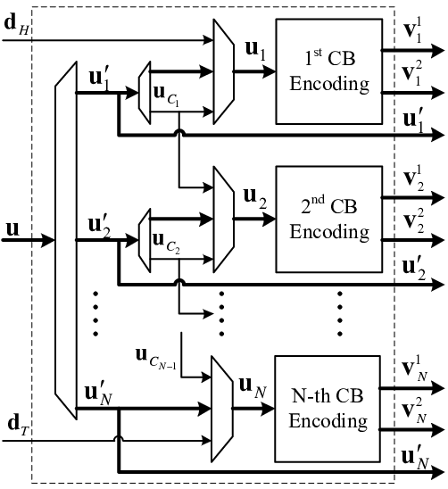
The detailed encoding process consists of three steps: 1) CB segmentation; 2) Information coupling and DBI; and 3) Turbo encoding, which are described as below:
Step 1 CB segmentation: Segment TB into information blocks, i.e., . Here, represents the concatenation operation of vectors , to . For , let represent the number of shared information bits between CBs and . Denote the length of the -th CB by , . Then, a TB is segmented in such a way: let the first information block have a length of ; let the -th information block , , have a length of ; and let the last information block have a length of .
Step 2 Information coupling and DBI: Construct CBs , through information coupling and DBI. Let be the coupled information bits between CBs and , , i.e., the information bits in information block shared by CBs and . We call as coupling length between CBs and . For the first CB , let , where is the dummy bits inserted into the first CB. For , let the -th CB . For the last CB , let , where is the dummy bits inserted into the last CB.
Step 3 Turbo Encoding: A Turbo encoder, which consists of two CC encoders and an interleaver, encodes the CBs. For a CB , the encoder generates the parity check sequences and by two CC encoders separately, and outputs , and as a codeword. Note that, as the dummy bits and are known by the receiver in advance, they do not need to be transmitted through communication channels. As well as this, the coupled information sequence , is only transmitted in the -th codeword and are not transmitted in the -th codeword .
Remark 1
As shown in [21] that the distance spectrum of DBI CCs depends on the number and the positions of these dummy bits in a CB. It is not affected by the value of the dummy bits. Therefore, all-zero dummy bits are considered in this paper, i.e., . In addition, we consider that the dummy bits are equally spaced or nearly equally spaced in a CB. The optimization of distributing the dummy bits in a CB is not considered in this paper.
Remark 2
The positions of coupled information bits in a CB will affect the decoding performance of the proposed scheme. In this paper, we consider that the coupled information bits are equally spaced or nearly equally spaced in the associated CBs. The optimization of distributing the coupled information bits in the associated CBs is not considered in this paper. We also consider that the coupled information bits of a CB with its previous and next CBs are independent, i.e., .
III-B Code Parameters Determination and Effective Code Rate
The encoding scheme described above introduced a set of code parameters , , , and . Now we first present how to determine these parameters for a given TB length and a given target effective code rate . Then, we will discuss the relationship between the effective code rate of an IC Turbo code to the mother code rate .
Firstly, the segmentation process in Step 1 of the encoding scheme guarantees
| (4) |
Then, recall that the dummy bits and are not transmitted in the output codewords and the coupled information sequences , are only transmitted once in Step 3 of the encoding scheme, the total output length of the proposed IC Turbo codes is written as
| (5) |
To satisfy the target effective code rate for a given TB length ,
| (6) |
should be satisfied.
Let be the set of positive integers and be the set of valid CB lengths in the LTE standard. Theoretically, any values of and can be selected. In practice, we prefer to have and maximize to exploit the best available coding gain. In addition, we consider in this paper. Setting leads to a simple encoding structure and a similar CB error rate (CBER) for all CBs in a TB, which will be shown in Fig. 4 in Section IV-B1. Setting guarantees the coupled information of a CB with its previous and next CBs can be independent. By considering these simplifications, (4) and (6) become11 1 In practice, one may not be able to select appropriate values for and to satisfy (7) and (8) for a given and . In that case, zero padding to is conducted to obtain a new TB of length to guarantee that an appropriate set of and can be selected to satisfy (7) and (8). In addition, should be minimized to save radio resources. Here, we assume (7) and (8) are satisfied for simplicity.
| (7) |
and
| (8) |
Now, we propose to select the code parameters in such a way to maximize (equivalent to minimize ) and satisfy (7) and (8)
| (9) | ||||
IV Decoding of the Proposed IC Turbo Codes
In the encoding scheme presented in Section III-A, we introduced coupled information between every two consecutive CBs. In this section, we first present the decoding scheme for one CB, namely intra-CB decoding. Based on that, we propose two inter-CB decoding schemes to decode the whole TB by exploiting the coupled information between every two consecutive CBs.
IV-A Intra-CB Decoding
We can see from Fig. 2 that each CB , , consists of three parts of information, which are illustrated in Fig. 3(a). The first part is the coupled information bits from the previous CB or the inserted dummy bits in the first CB, i.e., for CB , , or for CB . We call this part of information as pre-coupled information or head dummy bits, respectively. The second part is the information bits that are not coupled with other CBs, i.e., for CBs , , or for the last CB. Here represents the elements in exclude the elements in . This part of information is termed un-coupled information. The third part is the coupled information bits to the next CB or the inserted dummy bits in the last CB, i.e., for CB , , or for CB . This part of information is named post-coupled information or tail dummy bits. As mentioned in Section III-B that we consider in this paper, it guarantees each CB is a composite of all three information parts.

According to the composition of CB , its associated decoding block diagram is shown in Fig. 3(b). Let CH and be the channel information and the a priori LLR information associated with the pre-coupled information , CHn be the channel information about the un-coupled information, and CH and be the channel information and the a priori LLR information associated with the post-coupled information . Denote and the extrinsic LLR information about the pre-coupled information and the post-coupled information , respectively. In addition, let and represent the a priori information of the head and the tail dummy bits. Recall that we consider in this paper, since the decoder has perfect knowledge about these dummy bits.
To decode CB , the Turbo decoder takes in channel information CH, CHn and CH, and takes in the a priori information () and () to perform intra-CB iterative decoding. When a predefined intra-CB decoding stopping criterion is satisfied, such as a predetermined maximum number of Turbo iterations has been reached or the CB CRC does not detect an error, the decoder outputs as an estimation of CB . It also outputs the extrinsic information (except the first CB) and (except the last CB), which will be used in the inter-CB decoding process between CBs.
Note that this intra-CB decoder is almost the same as that for the LTE Turbo codes. The only difference is that the proposed decoder utilizes a priori information from adjacent CBs and outputs extrinsic information to them. This only affects the initialization and the outputs of the decoder. Therefore, we can almost keep the LTE Turbo decoder for a CB unchanged.
IV-B Inter-CB Decoding
Based on the intra-CB decoding scheme presented above, we propose two inter-CB decoding schemes to exploit the extrinsic information between coupled CBs to improve the TBER performance. The first decoding scheme, namely FF-FB decoding scheme, decodes serially from the first undecoded CB to the last undecoded CB and then, if it is necessary, decodes serially from the last undecoded CB to the first undecoded CB. This FF-FB decoding process can be repeated for a few times to achieve an excellent TBER performance. However, it suffers from a high decoding latency. As well as this, for a long coupling length , it has a high decoding complexity (more details will be shown in Section V). To decrease the decoding latency and the decoding complexity, we propose a WD decoding scheme for the proposed codes. It utilizes a window which consists of only two consecutive CBs and slides from the first CB to the last CB. It retains good TBER performance and has low decoding latency and decoding complexity. Next, we present the proposed inter-CB decoding schemes.
IV-B1 FF-FB Decoding Scheme
Let , denote the extrinsic (a priori) information associated with , which is forwarded from the -th CB to the -th CB. Let denote the extrinsic (a priori) information sent from the -th CB to the -th CB. The decoding scheme is described as below:
Step 1 Initialize: Let . Set the maximum intra-CB and inter-CB decoding iterations to and , respectively. Set the current inter-CB iterations to .
Step 2 FF Decoding: The inter-CB decoder decodes CBs serially from the first CB to the last CB. The forward information , , is calculated and passed down from the -th CB to the -th CB. The details are as below:
If , for the -th CB , the decoder uses the associated channel information and the a priori information about the pre-coupled information bits to estimate the CB. It also outputs the extrinsic information and associated with the post- and the pre-coupled information bits and , respectively.
Note that, in this decoding iteration, the backward a priori information associated with the post-coupled information bits is not available for the -th CB, i.e., . Therefore, only one round FF decoding cannot fully exploit the coupled information between CBs.
If , the inter-CB decoder decodes from the first undecoded CB to the last undecoded CB by using both a priori information and associated with the pre- and the post-coupled information bits to decode . Other details are identical to that of .
Increase the current inter-CB iterations by one, e.g., .
Step 3 FF TB CRC: Calculate TB CRC based on the estimations . If TB CRC detects an error and , go to Step 4; Otherwise, go to Step 6.
Step 4 FB Decoding: The inter-CB decoder decodes CBs serially from the last undecoded CB to the first undecoded CB. The decoding of each CB is identical to the FF decoding with .
Increase the current inter-CB iterations by one, e.g., .
Step 5 FB TB CRC: Calculate TB CRC based on the estimations . If TB CRC detects an error and , go to Step 2; Otherwise, go to Step 6.
Step 6 Output decoded CBs: Output , as the final estimations of .
Remark 3
The proposed FF-FB decoding scheme spreads reliable messages from the first and the last CBs to other CBs via FF and FB decoding processes, respectively. With a sufficiently large number of inter-CB decoding iterations, all CBs gradually approach the decoding performance of the first and the last CBs, which in turn improves the TBER performance. To show this reliable messages spreading phenomenon, we plot the CBER against the CBs’ indices and the inter-CB iterations in Fig. 4. The TB consists of CBs, the coupling length , the maximum number of inter-CB iterations is set to and the channel SNR dB. Clearly, it can be seen that the first and the last CBs have a much better CBER performance than that of other CBs in the first a few inter-CB iterations. As the decoding process progresses, all CBs gradually approach a similar CBER as that of the first and the last CBs.

The proposed FF-FB decoding scheme has a large TB decoding latency as the decoding process has to go through all CBs for a few iterations to achieve a good TBER performance. This also prevents using CB CRC as a TB-level early stopping criterion to save the receiver’s computational resources. To decrease the decoding latency and the decoding complexity, we next propose a WD decoding scheme.
IV-B2 WD Decoding Scheme
The proposed WD decoding scheme uses a window which consists of two consecutive CBs to decode a CB and slides from the first CB to the last CB. The -th decoding window, which is used to decode the -th CB, includes the -th and the -th CBs. The decoding process inside the -th window is described as below:
Step 1 Initialize: Obtain , the a priori information associated with the pre-coupled information of the -th CB, from the -th decoding window. Let , i.e., the -th CB does not generate extrinsic information about yet. Let , i.e., without a priori information from the -th CB. Set the maximum iterations in the decoding window to . Set the current decoding iterations .
Step 2 Decode the -th CB: Let , i.e., obtain the a priori information associated with the post-coupled information from the -th CB. Decode the -th CB using the a priori information and , and the channel information , and . Output the estimated -th CB and the extrinsic information associated with the post-coupled information .
Increase the current decoding iterations by one, i.e., .
Step 3 CB CRC for the -th CB: Calculate CB CRC based on . If CRC detects an error and , go to Step 4; Otherwise, go to Step 5.
Step 4 Decode the -th CB: Let , i.e., obtain the a priori information about from the -th CB. Decode the -th CB using the a priori information and , and the channel information , and . Output extrinsic information and . Go to Step 2.
Step 5 Output the estimation of the -th CB: If CB CRC for -th CB does not detect an error, output as the final estimation of the -th CB. Let . Move decoding window one CB to the right, i.e., move to the -th CB.
If CB CRC for the -th CB detects an error, stop decoding. Other CBs will not be decoded.
Remark 4
In the decoding process for the -th CB, the a priori information is always zero since the -th CB does not have the a priori information about from the -th CB. Therefore, the extrinsic information generated by the -th CB is inferior to that generated by the FB decoding process in the FF-FB decoding scheme. This in turn results in a decoding performance loss compared to the FF-FB decoding scheme. This performance loss will be shown in Section VII-A. However, the WD decoding scheme also achieves a considerable SNR gain compared to the LTE Turbo codes. Moreover, it decodes CBs on-the-fly, which leads to a low decoding latency and a low decoding complexity. We will discuss the decoding complexity of the proposed decoding schemes in the next section.
V Computational Complexity of the Proposed Decoding Schemes
In this section, we discuss the decoding complexity of the proposed decoding schemes. As discussed in Section IV-A, the intra-CB decoder for our proposed scheme is almost the same as that for the LTE Turbo codes. Therefore, we count the decoding complexity for a length- CB as an unit and consider a length TB for the discussion of computational complexity hereafter.
In the LTE standard, the TB is segmented into length- CBs22 2 In the LTE standard, the TB segmentation rules result in CBs with similar lengths, but not necessarily exact the same length of . Here, we assume all CBs are of the same length for simplicity., which results in a maximum computational complexity of . Here, rounds up argument to the smallest positive integer. We use this maximum computational complexity as a reference for that of our proposed decoding schemes.
V-A Computational Complexity of the FF-FB Decoding Scheme
In our proposed encoding scheme, the TB is segmented into CBs according to (7). Therefore, the maximum computational complexity for one FF-FB decoding iteration is . Consider a maximum number of inter-CB iterations of , the overall computational complexity is written as
| (11) |
Here, is the fraction of undecoded CBs in a TB in iteration . Obviously, because all CBs need to be decoded in the first iteration.
We can see from (11) that the overall computational complexity of the proposed FF-FB decoding scheme is determined by , for a given , which is in turn determined by the channel quality, the FER performance of the underlying Turbo code and the number of CBs in a TB. Unfortunately, a closed-form expression for the FER performance of the LTE Turbo code is not available in general. As a result, we investigate the average number of decoding for one CB and the normalized computational complexity by simulations for various TB lengths and various coupling lengths . Some results are shown in Fig. 5.

It can be seen from the left hand side of Fig. 5 that for coupling length to , the average number of decoding for one CB of the FF-FB decoding scheme grows from 1.05 to 3.3 at a TBER level of . This is because when the coupling length increases, we need more inter-CB decoding iterations to fully exploit the benefits provided by the coupled information. However, we will see in Section VII-B that the increased average number of decoding iterations also increases the SNR gain of our proposed IC Turbo codes over the LTE Turbo codes. The normalized overall computational complexity, which is defined as the average number of decoding for one CB multiplied by , is shown in the right hand side of Fig. 5. The normalized overall computational complexity ranges from 1.3 to 4 times of the maximum computational complexity of the LTE Turbo codes when increases from to .
V-B Computational Complexity of the WD Decoding Scheme
As in the FF-FB decoding scheme, the lack of closed-form FER expression of the LTE Turbo code prevents us obtaining a closed-form expression of computational complexity for the WD decoding scheme. Therefore, We also investigate its computational complexity by simulations and show some results in Fig. 5.
We can see from the left hand side of Fig. 5 that for coupling length to , the average number of decoding for one CB of the WD decoding scheme grows from 1.08 to 2 at a TB error rate level of . When , the WD and FF-FB decoding schemes have a similar average number of decoding per CB. However, when and , the WD decoding scheme has a much lower average number of decoding iterations. The normalized overall computational complexity for the WD decoding scheme is also shown in the right hand side of Fig. 5. Generally speaking, for the coupling length to , the overall computational complexity of the WD decoding scheme is about to times of that of the LTE Turbo codes. Moreover, it can be seen that for various TB lengths and a relatively large coupling length, e.g., , the WD decoding scheme has a much lower computational complexity than that of the FF-FB decoding scheme. In particular, the WD decoding scheme saves computational resources compared to the FF-FB decoding scheme when .
VI EXIT Chart Analysis
In this section, we develop EXIT functions for the LTE Turbo codes and our proposed IC Turbo codes. We also propose an upper bound for the SNR gain of our proposed codes over the LTE Turbo codes, which can be calculated by the developed EXIT functions.
VI-A Decoder Model and EXIT Chart Preliminaries
EXIT chart is widely used to analyze the convergence behavior of iterative decoders [23]. It evaluates the relationship between the average extrinsic information generated by a soft-input-soft-output (SISO) decoder and its input average a priori information . Plotting the EXIT functions of two constituent SISO decoders together, one can clearly and intuitively predict the iterative decoding behavior of an iterative decoder and observe the decoding trajectory.
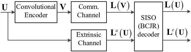
To construct the EXIT function of a SISO decoder, a general information theoretic decoder model was introduced in [29]. We adopt this decoder model for a component CC in Turbo codes as shown in Fig. 6. Let and represent the random variables with realizations of and . The SISO decoder, which is a BCJR decoder, uses channel observation LLRs from communication channel and a priori LLRs delivered by extrinsic channel to compute the extrinsic LLRs as well as a posteriori LLRs . The LLRs are defined as in (2). The communication channel models the real physical channel. It also takes into account the rate-matching device and adaptive modulator at the transmitter side, and the soft demodulator and de-rate-matching device at the receiver side. The extrinsic channel is an artificial channel which conveys the a priori LLRs from other sources, such as another constituent decoder and the decoders for the coupled CBs in our proposed IC Turbo codes.
VI-B EXIT Functions for CCs in LTE Turbo Codes
In LTE, code rates that lower than the mother code rate are achieved by repetition. Denote the effective code rate after repetition. According to the LTE rate-matching mechanism [26], the maximum number of repetitions for a coded bit in is written as
| (12) |
Let and , , be the fraction of coded bits in that are repeated by times. Then
| (13) |
Eq. (13) means that there are at most two kinds of bits in which are repeated by and times. Denote them by and respectively. Consider a physical AWGN channel with SNR , it is known that the effective SNR for a coded bit is proportional to the number of repetitions for this bit, i.e., the effective SNR is for a coded bit repeated by times. Assume a large enough channel interleaver, and can be considered to be transmitted through two independent communication channels with different effective SNRs [24] of and , respectively.
Now, let us consider the average information delivered by the communication channel. Let , and be the noise variances of the physical AWGN channel, the equivalent communication channel for and the equivalent communication channel for , respectively. We convert these variances to the variances of their associated output LLRs [23], i.e., , and . Then we have
| (14) |
Let be the mutual information between and , and be the mutual information between and . The average information delivered by about is written as
| (15) |
where [23]
| (16) |
Inserting (13) and (14) into (15) results in
| (17) |
With the average channel information , we now construct EXIT functions for the LTE Turbo codes with repetition from that of the LTE mother Turbo code. As the BCJR decoder is identical for both codes for the same CB length, the decoder generates identical extrinsic information if the channel information and the a priori information received by the BCJR decoder are of the same value and have the same distribution. Therefore, the EXIT functions for the LTE Turbo codes with repetition can be derived by
| (18) |
Here, is the EXIT function for the CC in an LTE Turbo code with repetition, is the EXIT function for the CC in the LTE Turbo mother code, is the a priori information conveyed by the extrinsic channel, and is calculated by
| (19) |
In (18) and (19), we only consider that the value of channel information is identical for the LTE Turbo codes with repetition and the LTE mother Turbo code. Strictly speaking, the distribution of the channel information should also be identical for the BCJR decoder to generate the same output extrinsic information. We generate the EXIT functions for the CCs in the LTE Turbo codes with repetition by using (18) and (19). We also obtain the EXIT functions through Monte Carlo simulations based on random repetition33 3 It has been shown in [24] that the EXIT charts obtained from random repetition can be used as a close approximation for the deterministic repetition scheme used in LTE., i.e., and are selected randomly from . The results are shown in Fig. 7. It can be seen that the EXIT functions constructed by our proposed method are well fitted with the simulated results for various code rates.

VI-C EXIT Functions for CCs in our Proposed IC Turbo Codes
Recall that the intra-CB decoding scheme for the proposed IC Turbo decoder takes in three parts of information to estimate a CB. Therefore, the extrinsic channel for the CC decoder of the proposed IC Turbo codes consists of three information channels: the extrinsic channel that conveys the a priori information from the other constituent BCJR decoder; the pre-coupled information channel that delivers the a priori information from the previous CB (or dummy bits ); and the post-coupled information channel that delivers the a priori information from the post-coupled CB (or dummy bits ). Note that, and are fixed in the intra-CB decoding process and evolve in the inter-CB decoding process since we only exchange information between CBs in the inter-CB decoding process.
As and evolve with the inter-CB decoding progress, the EXIT function for the CC decoder in our proposed IC Turbo code becomes a series of EXIT functions. This results in a big challenge to calculate an exact EXIT function for the CC decoder in our proposed scheme. Instead, we propose to construct the EXIT function for the case where the pre-coupled information bits and the post-coupled information bits are assumed to be perfectly known by the decoder. Though this may over estimate the a priori information and , it simplifies the construction of EXIT functions for our proposed codes. Moreover, it provides a decoding threshold lower bound for our proposed IC Turbo codes. We propose to use this decoding threshold lower bound to estimate the maximum SNR gain of our proposed IC Turbo codes over the LTE Turbo codes. We call this maximum SNR gain as SNR gain upper bound. Simulation results show that the proposed SNR gain upper bound has an accuracy within 0.1 dB for a set of code parameters, which will be shown in Table I and Fig. 10.
Now, we construct the EXIT function for the CC decoder in our proposed IC Turbo codes by assuming perfect a priori information and . In [22], the authors proposed an effective way to construct the EXIT chart for the CC decoder in DBI Turbo codes by shifting the EXIT chart for the underlying CC decoder to an operation point with a higher a priori information. It has been confirmed by simulation results that in the AWGN channels, the EXIT functions constructed by the proposed method are well fitted with the simulation results when the fraction of dummy bits is not higher than . By assuming perfect a priori information and , our proposed IC Turbo codes can be viewed as a kind of DBI Turbo codes with fraction of dummy bits of . Thus, we adopt this method to construct the EXIT function for the CC in our proposed IC Turbo codes.
As the pre-coupled and post-coupled information bits are assumed to be perfectly known by the decoder, the a priori information and are written as
| (20) |
Since both and convey the information about the pre-coupled information bits, the redundant a prior information should be removed from the total a priori information . By the same token, the redundant a prior information in both and about the post-coupled information bits should be removed. Recall that, we consider in this paper that the pre-coupled information bits and the post-coupled information bits of a CB are independent. Thus, the a priori information for the CC decoder is written as
| (21) |
Now, the EXIT function for the CC in our proposed IC Turbo codes can be constructed by
| (22) |
where is the EXIT function for the CC in an IC Turbo code and is the EXIT function for the CC in the Turbo mother code. are related by (21) and is the variance of .
We generate the EXIT functions for the CCs in our proposed IC Turbo codes from that of the underlying CC by using (21) and (22). We also obtain the EXIT functions through Monte Carlo simulations based on random DBI. The EXIT functions for various coupling percentages are shown in Fig. 8. It can be seen that the EXIT functions constructed by our proposed method agree with the simulation results well when the percentages of coupled information bits are and .

VII Numerical Results
In this section, we present the numerical results of our proposed IC Turbo codes and the LTE Turbo codes under AWGN channels. We first compare the TBER performance of the FF-FB and the WD decoding schemes for various IC Turbo codes. Then the SNR gains of our proposed codes under the FF-FB decoding scheme over the LTE Turbo codes for various TB lengths and coupling lengths are investigated. We compare the simulated SNR gains with the proposed SNR gain upper bounds to validate our proposed EXIT chart functions. At last, we compare the TBER performance of our proposed codes with the WD decoding scheme to that of the LTE Turbo codes for various TB lengths and coupling lengths .
In all simulations, the CB length and the maximum number of intra-CB decoding iterations are considered. The maximum number of inter-CB iterations is set to for the FF-FB scheme and for the WD decoding scheme, respectively.
VII-A Comparison of the FF-FB and WD Inter-CB Decoding Schemes
Fig. 9 depicts the TBER performance of our proposed FF-FB and WD inter-CB decoding schemes for three IC Turbo codes with and , respectively. It can be seen from Fig. 9 that for all codes, the FF-FB decoding scheme has a better TBER performance than that of the WD decoding scheme at the same SNR level. As discussed in Section IV-B Remark 4, this is because the extrinsic information from the post-coupled CB for the WD decoding scheme is inferior to that for the FF-FB decoding scheme. Moreover, it can be seen that the SNR gain of the FF-FB decoding scheme over the WD decoding scheme increases with the coupling length . This means the effect of lacking a priori information from the -th CB for the -th decoding window becomes significant as the coupling length increases.

As the FF-FB decoding scheme has a better TBER at the same SNR level than that of the WD decoding scheme, we will use the FF-FB decoding scheme to evaluate the performance limit of our proposed codes next. On the other hand, the WD decoding scheme has a lower decoding latency and a lower decoding complexity than that of the FF-FB decoding scheme, we will use the WD decoding scheme in Section VII-C to investigate the SNR gains of our proposed codes over the LTE Turbo codes for practical purposes.
VII-B Simulated SNR Gains vs the Proposed SNR Gain Upper Bound
We use the EXIT charts developed in Section VI to calculate the decoding thresholds of the LTE Turbo codes and our proposed codes for various code rates. The proposed SNR gain upper bound in Section VI-C is calculated as the gap between the decoding thresholds of a proposed code and a LTE Turbo code with the same code rate. The calculated results are shown in Table I. It can be seen that the SNR gain upper bound increases with the coupling length .
| Code Rate | Proposed Codes | LTE Turbo Codes | SNR Gain Upper Bound (dB) | |
|---|---|---|---|---|
| Coupling Length | Decoding Threshold (dB) | Decoding Threshold (dB) | ||
| 0.318 | 384 | -5.22 | -4.92 | 0.3 |
| 0.3 | 768 | -5.78 | -5.16 | 0.62 |
| 0.286 | 1024 | -6.1 | -5.34 | 0.76 |
The simulated TBERs of the LTE Turbo codes and the proposed codes with the FF-FB decoding scheme are demonstrated in Fig. 10. We can learn from the simulation results that for and , the simulated SNR gains for various code rates are within 0.1 dB from the proposed SNR gain upper bound at a TBER level of . This confirms that the developed EXIT charts in Section VI are valid and the proposed SNR gain upper bound is tight for various coupling lengths. In addition, our simulation results show that the proposed FF-FB decoding scheme for our proposed codes can effectively exploit the benefits introduced by the coupled information because it achieves the SNR gain upper bound within 0.1 dB.

VII-C TBER Performance of the Proposed IC Turbo Codes under WD Decoding
In this section, we evaluate the TBER performance of our proposed codes with the WD decoding scheme and compare it to that of the LTE Turbo codes with the same code rates. In particular, we investigate the effect of the TB length and the coupling length on the TBER performance of the proposed codes.
Fig. 11 shows the TBER performance of the proposed codes with and , and that of the corresponding LTE turbo codes. We can see that our proposed codes have considerable SNR gains over the LTE Turbo codes for various TB lengths. When increases from to , the SNR gain increases from 0.44 dB to 0.53 dB at a TBER of and increases from 0.43 dB to 0.5 dB at a TBER of .

Fig. 12 shows the TBER performance of the proposed codes with and , and that of the corresponding LTE turbo codes. It can be seen from Fig. 12 that our proposed codes have significant SNR gains for various coupling lengths compared to the LTE Turbo codes. Furthermore, when coupling length increases from to for the same TB length, the SNR gain increases from 0.26 dB to 0.52 dB at a TBER of .

VIII Summary
In this paper, we proposed a new class of IC Turbo codes by sharing information bits between adjacent CBs. Two inter-CB decoding schemes are proposed to exploit the coupled information introduced by the encoding scheme. The proposed schemes achieve a considerable TBER performance improvement compared to conventional LTE Turbo codes. New EXIT chart construction method is proposed for the LTE Turbo codes from that of underlying CC. An SNR gain upper bound of our proposed codes over the LTE Turbo codes is derived by using our proposed EXIT charts. Intensive simulation results show that the proposed codes have considerable SNR gain compared to the conventional LTE Turbo codes.
This information coupling technology can be extended to other channel codes, such as LDPC codes. A few problems regarding information coupling technology need to be addressed in the future. First of all, the coupled information of a CB can be extended from adjacent CBs to more CBs. In addition, the coupling length can be optimized to further improve the TBER performance.
References
- [1] A. Larmo, M. Lindstrm, M. Meyer, G. Pelletier, J. Torsner and H. Wiemann, “The LTE link-layer design,” IEEE Comm. Mag., vol. 47, no. 4, pp. 52-59, Apr. 2009
- [2] P. Hung-Ta, Y. S. Han and Yu-Jung Chu, “New HARQ scheme based on decoding of tail-biting convolutional codes in IEEE 802.16 e,” IEEE Trans. Veh. Tech., vol. 60, No. 3, pp. 912–918, Mar. 2011.
- [3] 3GPP TS 36.213, “LTE, evolved universal terrestrial radio access (E-UTRA), physical layer procedures,” Release 13, May 2016.
- [4] J. G. Andrews, S. Buzzi, W. Choi, S. V. Hanly, A. Lozano, A. C. Soong and J. C. Zhang, “What will 5G be?,” IEEE J. Sel. Area. Comm., vol. 32, no. 6, pp. 1065–1082, Jun. 2014.
- [5] 3GPP TSG-RAN WG1 #86, “Discussion on outer coding on eMBB data,” LG Electronics, Aug. 2016.
- [6] 3GPP TSG-RAN WG1 #86, “Erasure coding evaluation methodology,” Qualcomm, Aug. 2016.
- [7] A. J. Felstrom and K. Zigangirov, “Time-varying periodic convolutional codes with low-density parity-check matrix,” IEEE Trans. Info. Theory, vol. 45, no. 6, pp. 2181-2191, Sep. 1999.
- [8] D. G. M. Mitchell, M. Lentmaier and D. J. Costello, “Spatially coupled LDPC codes constructed from protographs,” IEEE Trans. Info. Theory, vol. 61, no. 9, Sep. 2015.
- [9] M. Stinner and P. M. Olmos, “On the Waterfall Performance of Finite-Length SC-LDPC Codes Constructed From Protographs,” IEEE J. Sel. Area. Comm., vol. 34, no. 2, pp. 345-361, Feb. 2016.
- [10] V. A. Chandrasetty, J. J. Sarah and L. Gottfried, “Memory-efficient quasi-cyclic spatially coupled low-density parity-check and repeat-accumulate codes,” IET Comm., vol. 8, no. 17, pp. 3179-3188, Nov. 2014.
- [11] Y. Xie, L. Yang, P. Kang and J. Yuan, “Euclidean geometry based spatially-coupled LDPC codes for storage,” IEEE J. Sel. Area. Comm., vol. 34, no. 9, pp. 2498-2509, Aug. 2016.
- [12] K. Liu, M. El-Khamy and J. Lee, “Finite-Length Algebraic Spatially-Coupled Quasi-Cyclic LDPC Codes,” IEEE J. Sel. Area. Comm., vol. 64, no. 12, pp. 4936-4945, Dec. 2016.
- [13] M. Zhang, Z. Wang, Q. Huang and S. Wang, “Time-Invariant Quasi-Cyclic Spatially Coupled LDPC Codes Based on Packings, ” IEEE Trans. Comm., vol. 34, no. 2, pp. 329-344, Dec. 2015.
- [14] C. Liang, X. Ma, Q. Zhang and B. Bai, “Spatial Coupling of Generator Matrices: A General Approach to Design Good Codes at a Target BER, ” IEEE Trans. Comm., vol. 62, no. 12, pp. 4211-4219, Dec. 2014.
- [15] A. R. Iyengar, P. H. Siegel, R. L. Urbanke and J. K. Wolf, “Windowed decoding of spatially coupled codes,” IEEE Trans. Info. Theory, vol. 59, no. 4, pp. 2277-2292, Dec. 2013.
- [16] M. Zhu, D. G. M. MitChell, M. Lentmaier, D. J. Costello and B. Bai, “Braided Convolutional Codes with Sliding Window Decoding, ” IEEE Trans. Comm., May 2017.
- [17] A. R. Iyengar, M. Papaleo, P. H. Siegel, J. K. Wolf, A. Vanelli-Coralli and G. E. Corazza, “Windowed decoding of protograph-based LDPC convolutional codes over erasure channels,” IEEE Trans. Info. Theory, vol. 58, no. 4, pp. 2303-2320, Nov. 2011.
- [18] S. Moloudi, M. Lentmaier and A. Amat, “Spatially coupled turbo codes,” IEEE 8th ISTC, pp. 82–86, 2014.
- [19] A. Amat S. Moloudi and M. Lentmaier, “Spatially Coupled Turbo Codes: Principles and finite length performance,” IEEE 11th ISWCS, pp. 883–887, 2014.
- [20] M. Lentmaier, A. Sridharan, Jr. Costello, Jr, and K. Zigangirov, “Iterative decoding threshold analysis for LDPC convolutional codes,” IEEE Trans. Info. Theory, vol. 56, no. 10, pp. 5274-5289, Sep. 2010.
- [21] X. Wen and J. Romme, “A class of multirate convolutional codes by dummy bit insertion,” in Proc. IEEE Globecom 2000, vol. 2, pp. 830–834, Nov. 2000.
- [22] T. Breddermann and V. Peter, “Rate-compatible insertion convolutional turbo codes: Analysis and application to LTE,” IEEE Trans. Wireless Comm., vol. 13, no. 3, pp. 1356–1366, Mar. 2014.
- [23] S. ten Brink, “Convergence behavior of iteratively decoded parallel concatenated codes.” IEEE Trans. Comm., vol. 49, no. 10, pp. 1727–1737, Oct. 2001.
- [24] T. Breddermann, and P. Vary. “EXIT Chart Optimized Rate Matching for Wireless Communication Systems,” IEEE VTC-fall 2011, pp. 1–5, 2011.
- [25] T. Breddermann, and P. Vary. “EXIT functions for parallel concatenated insertion convolutional codes,” IEEE GLOBECOM 2011, 2011.
- [26] 3GPP TS 36.212, “LTE, evolved universal terrestrial radio access (E-UTRA), multiplexing and channel coding,” Release 13, Apr. 2016.
- [27] L. Bahl, J. Cocke, F. Jelinek and J. Raviv, “Optimal decoding of linear codes for minimizing symbol error rate,” IEEE Trans. Info. Theory, vol. 20, no. 2, pp. 284–287, Nov. 1979.
- [28] J. F. Cheng and K. Havish, “Error detection reliability of LTE CRC coding,” IEEE VTC-Fall 2008, Oct. 2008.
- [29] A. Ashikhmin, K. Gerhard, and S. ten Brink, “Extrinsic information transfer functions: model and erasure channel properties,” IEEE Trans. Info. Theory, vol. 50, no. 11, pp. 2657–2673, Nov. 2004.