Subcarrier-Chunk Assignment With Power Allocation and Multiple-Rate Constraints for Downlink OFDMA
Abstract
We consider downlink OFDMA in which users are imposed with different proportional-rate constraints, and a base station would like to maximise user rate over subcarrier assignment (SA) and power allocation (PA). To attain the objective, we propose a chunk-based SA and low-complexity PA algorithms. Numerical results show that the proposed SA and PA can provide higher average minimum achievable rate than the existing schemes while keeping the deviation from the rate constraint small for both single-cell and multi-cell systems with fractional frequency reuse.
I Introduction
In orthogonal frequency division multiple access (OFDMA), mobile users can be dynamically assigned to transmit in different sets of subcarriers based on their channel qualities. An approach called rate adaptive allocation is commonly used to dynamically allocate resource to maximise a total throughput. To achieve this goal, only the user with the best channel quality is assigned subcarriers for data transmission. However, this results in an unfair assignment to other users.
Fair resource allocation was proposed in various work concerning both wireless and wireline channels. In [2], Rhee and Cioffi proposed an algorithm that achieves proportional-rate fairness through maximising the minimum user’s throughput. However, this approach is inapplicable to a system in which users have different requested rates. To address this issue, Shen et al. [3] and Ren et al. [4] formulated a nonlinear optimisation problem that guarantees multiple-rate fairness. However, determining the solution to this nonlinear problem can be computationally complex. One way to reduce complexity is to assign subcarriers to users in a group or chunk of adjacent subcarriers in OFDMA networks [5, 6]. Since the number of channel-filter taps is much lower than the number of total subcarriers, adjacent subcarriers are highly correlated. Therefore, if the subcarriers are appropriately grouped together and selected for users, the resulting achievable rate can approach that of a single-subcarrier-based resource allocation at a lower computational cost.
For this work (and our conference proceeding [1]), we propose a chunk-based subcarrier assignment (SA) based on [2] and [3]. For a given subcarrier assignment, we propose a power allocation (PA) based on a low signal-to-noise ratio (SNR) approximation. With this approximation, the problem is linearized, and its solution can be easily obtained. The chunk-based allocation problem we consider here is significantly different from that in [5, 6] which consider average BER (bit error rate) constraint instead of proportional-rate constraint. Since there is no equivalent chunk-based SA scheme existing in the literature, we modify the single-subcarrier based scheme by [3] to assign subcarriers in chunk for the purpose of performance comparison. Numerical results show that our proposed allocation scheme improve the average minimum user’s achievable rate over the modified scheme based on [3] in all SNR regimes. The rate gain is larger when SNR is low.
We extend our work in [1] to multi-cell channels in which intercell interference can be significant. To mitigate the interference and improve cell-edge performance, intercell interference coordination (ICIC) such as frequency reuse planning is adopted to restrict resource allocation among different cells in the network [7]. By using a frequency reuse factor of 1 (FRF-1), high peak data rate can be achieved at a cost of high interference levels at the cell edges. On the contrary, by using a frequency reuse factor of more than 1 (or less than 1, depending on the notation), interference level can be reduced at a cost of a lower spectrum utilisation [8]. Fractional frequency reuse (FFR) is a promising ICIC technique for OFDMA network wherein cells are partitioned into regions with different FRF’s [9] and is proposed for next-generation wireless systems [10]. We apply the proposed chunk-based SA with uniform PA in multi-cell setting with FFR and show that the resulting rate is larger than static SA by as much as 400%.
II Single-Cell Resource Allocation
First we consider a single-cell downlink OFDMA network, which consists of a base station and mobile users. This model is applicable to a cellular network with a large frequency-reuse factor, in which intercell interference is negligible. The channel between the base station and any user is assumed to be frequency-selective fading with order for which channel-filter taps are denoted by . Assuming total subcarriers, the frequency response of user on subcarrier can be obtained by taking a discrete Fourier transform (DFT) of the channel impulse response as follows
| (1) |
For data transmission from the base station, each user is assigned chunk(s) of contiguous subcarriers. For 3GPP LTE-Advanced, the minimum subcarrier assignment unit is one resource block, which consists of 12 subcarriers. Each chunk of subcarriers is exclusively used by a single user; therefore, there is no interference from other users in the cell. Let be the total number of subcarrier chunks, which is greater than or equal to the number of users (). Hence, each user will be assigned at least one chunk. The number of chunks where is a chunk size and remaining subcarriers will be appended to the last chunk.
The sum achievable rate for user is given by
| (2) |
where indicates whether user is assigned to transmit in chunk . Since only one user is assigned to transmit in each subcarrier chunk at any moment, for ,
| (3) |
Because the data signal in each subcarrier is only corrupted by additive white Gaussian noise with zero mean and variance , the achievable rate per subcarrier for user in chunk per subcarrier is given by
| (4) |
where is the transmission power allocated for user in subcarrier .
The objective of the proposed resource allocation is to maximise the sum achievable rate of all users over chunk assignment and power allocation, subject to total-power and proportional-rate constraints. Assuming that users can have different rate requirement, we let be a ratio of the requested rates of user 1 through user . Thus, the optimisation problem can be stated as follows:
| (5) | ||||
| subject to | (6) | |||
| (7) | ||||
| (8) | ||||
| (9) | ||||
| (10) |
Finding the solution to this integer-nonlinear problem is prohibitively complex. Also, due to a strict fairness constraint in (10), solutions may not exist at all. To reduce complexity of the problem, we propose to find a suboptimal solution by breaking the problem into two subproblems. The first subproblem is SA in which uniform transmit power over all subcarriers is assumed. Then, with the specific sets of subcarrier assignment obtained from solving the first subproblem, PA is subsequently performed. From the numerical results, when the number of chunks is sufficiently large, a mere subcarrier assignment assuming uniform power can roughly satisfy the proportional-rate constraints
II-A Subcarrier Assignment
For both SA’s proposed by [2] and [3], in the first iteration, subcarriers are sequentially assigned to the users based on channel gains. Thus, the subcarrier with the highest gain is assigned to the first user. This gives undue favour to the first user and as a result, the first user generally has the highest average rate whereas the last user generally has the lowest average rate. This discrepancy becomes more apparent with larger chunk size. Moreover, subcarrier assignment based only on absolute channel gain might not result in the largest sum throughput. To reduce the mentioned discrepancy, our proposed SA removes the serial assignment in the first iteration, and changes the assignment criterion from the achievable rate of a user to the normalised rate defined as a ratio between rate of a user and average rate of all users for that chunk. The normalised rate of user in chunk is given by
| (11) |
For the given subcarrier assignment, uniform power allocation across all subcarriers is assumed, i.e., .
In the first iteration of the proposed algorithm, the base station registers the chunks with the highest normalised rate for each user . To maximise the minimum user’s rate, the registered chunk with the smallest normalised rate over its requested rate will be selected and assigned to the corresponding user. The user that has already been assigned a chunk will be removed from the assignment pool . This step is repeated until all users are assigned one chunk each. The algorithm is stated in Algorithm 1. In subsequent iterations, all users are back in the assignment pool. In each iteration, the user with the smallest is assigned the chunk that maximises the normalised rate over all the remaining chunks. This step is iterated until all chunks are assigned. We denote the set of chunks assigned to user by . Thus, Algorithm 1 gives nonoverlapping sets of which their union spans all chunks. Let be the number of subcarriers assigned to user . Therefore, .
To determine the complexity of the proposed SA algorithm and compare with the algorithm proposed by [3], we count the number of -computations and the number of comparisons required in the algorithm. We note that finding the extremum of entries requires at most comparisons. Both the proposed SA algorithm and the algorithm by [3] needs to know the instantaneous rate of each subcarrier for each user and thus, requires -computations.
For the proposed SA, there are comparisons in the initial phase and comparisons in the second phase. Thus, the total number of comparisons increases as as and increase. For the single-subcarrier-based SA by [3], the initial phase requires while the second phase requires comparisons. Thus, the number of comparisons increases as . For a moderate and large chunk size, could be much greater than and and the algorithm in [3] will require much larger number of comparisons than our chunk-based algorithm.
II-B Power Allocation
| (12) | ||||
| subject to | (13) | |||
| (14) | ||||
| (15) |
This PA for each subcarrier was solved by [3]. Since we will borrow some definitions from [3], the solution by [3] will be briefly described first. For the subcarrier assignment of user denoted by , each subcarrier is ordered by a ratio of its squared channel magnitude to the noise power in an increasing order, i.e., . The optimal power for user is then computed by [3]
| (16) |
and the total power allocated for user is given by
| (17) |
where
| (18) |
To find the set of optimal total power allocated to all users , the following nonlinear system needs to be solved [3]
| (19) |
and
| (20) |
where for ,
| (21) |
Solving (19) and (20) can be complex and requires some numerical methods. To simplify the PA problem, we propose to linearize the nonlinear system and thus, reduce the complexity of the problem. We apply a low-SNR approximation and obtain a suboptimal but linear PA problem. This low-SNR approximation is well justified since power allotted for each subcarrier is usually small due to a large number of subcarriers. Per subsequent numerical examples, the proposed solution also performs well even for a moderate-SNR system.
The ratio between the actual and desired rates can be approximated as follows
| (22) | ||||
| (23) |
For (23), we assume low-SNR regime, i.e., , and apply the approximation when . With (23) and the proportional rate constraint
| (24) |
we obtain a linear system with equations and unknowns with the following matrix equation
| (25) |
where
| (26) | ||||
| (27) |
and
| (28) |
The solution of the linear system (25) can be easily obtained as follows
| (29) | ||||
| (30) |
We remark that the solution presented arises from the low-SNR approximation and sometimes may not be feasible, i.e., some powers are negative. To remedy this negative-power solution, we propose to allocate uniform power for the group of users with the smallest powers (including all users with negative power). The number of users in this group will be just large enough that their combined transmit power exceeds zero. All other users not in this group will be allocated power according to the solution in (29) and (30). The steps of the proposed power allocation are shown in Algorithm 2. If for all , the proposed PA is straightforward.
We note that if , then according to (17), . To find a feasible solution, the subcarriers with smallest channel gains will be allocated zero power. Thus, subcarriers whose channel gains are below some threshold will not be use for transmission, similar to a water-filling scheme. This process is repeated until .
Reference [3, 11] also proposed to linearize (19) but with different approach. Both work assume that the ratio between the number of subcarriers assigned to each user and its requested rate is fixed for all users, . This assumption does not often hold true and hence, may not be as practical as the low-SNR assumption. The resulting linear system appeared in [3, 11] differs from (25), but has similar structure. When SNR is high, reference [3, 11] made another approximation for (19), but still ended up with nonlinear equation.
III Multi-Cell Subcarrier Assignment
For a multi-cell channel, FFR is applied as follows. First, available transmission bandwidth is divided into two bands, namely cell-centre and cell-edge bands, as shown in Fig 1. Since users in a cell-centre region is less susceptible to intercell interference, the frequency reuse factor for the cell-centre group is set to 1 to enhance spectrum efficiency. The bandwidth range for cell-centre users is denoted by F1. However, the reuse factor for cell-edge users is set to be 3 with 3 different nonoverlapping frequency ranges denoted by F2, F3, and F4.


Group membership can be determined by a threshold based on the received signal strength or the distance between the user and the base station denoted by [12]. Assuming that the cell radius is and the cell-centre radius is , users with distance away from the base station will be in a cell-centre group while users with distance will be in a cell-edge group. Finding a proper threshold or radius of the cell centre, , is usually heuristic [13]. Assuming that there are users in each cell, we denote the number of cell-centre users and cell-edge users by and , respectively, and . Let us denote the set of users in the cell-centre group by and that in cell-edge group by . For a network with uniformly distributed users, the optimal number of subcarriers allocated to the cell-centre group and the cell-edge group is proportional to a coverage area [14] and is given by
| (31) | ||||
| (32) |
Assuming that chunk size is fixed at , the number of chunks for cell-centre and cell-edge users are given by and , respectively.
We consider a 2-tier 19-cell network shown in Fig. 2. With the proposed FFR, a user in cell-centre area is interfered by all 18 other cells while a user in cell-edge area is interfered by 6 other cells only.

We approximate the SINR for user in the cell-centre area of cell 1 on the th subcarrier as follows
| (33) |
where is a squared channel gain from base station and can be computed from channel impulse response similar to (1) and propagation path loss in decibel for interfering signal from base station is given by [12]
| (34) |
where is the distance in kilometre from base station to base station 1. The approximation discards path loss of the desired signal due to the distance from base station 1 to the user since that distance is much shorter than . We also assume uniform power allocation over all subcarriers since adaptive power allocation for all cells in the network is not practical due to required complex coordination among base stations. Moreover, references [15] and [16] suggest that improvement from adaptive power allocation is marginal over a wide range of SNR’s when only subcarriers with high gain are selected. Similarly, the SINR of cell-edge user in cell 1 on subcarrier is approximated by
| (35) |
Given target BER, an effective sum rate per subcarrier in chunk for user can be computed by
| (36) |
where [12, 17] and the sum rate for user in either cell-centre or cell-edge areas over all chunks is given by
| (37) |
where indication functions for user in chunk in cell-centre and cell-edge area are denoted by and , respectively.
We would like to maximise the sum throughput for cell 1 while maintaining proportional-rate fairness among the users in the cell. Since the transmit power from all base stations is fixed, we assign chunk of subcarriers to users in cell 1 to maximise the throughput. The two groups of users may adhere to different proportional-rate fairness. The SA problem can be stated as follows
| (38) | ||||
| subject to | (39) | |||
| (40) | ||||
| (41) | ||||
| (42) | ||||
| (43) |
where , , and and are the requested rates for cell-centre user and cell-edge user , respectively.
The problem stated in (38) can be divided into two subproblems and each subproblem maximises the sum rate of users in each group. Thus, we can apply the proposed SA stated in Algorithm 1 in Section II-A to solve each subproblem. The complexity of this SA follows the discussion at the end of Section II and increases with the number of users in the cell considered.
IV Numerical Results
In this section, the performance of the proposed SA and PA is shown and compared with existing schemes. Two main performance indices are the averaged minimum user’s achievable rate and the average rate constraint deviation, , which indicates how well the proposed scheme conform to the proportional-rate constraint. is defined in [3] as
| (44) |
where the expectation is over channel realisation. For the optimal solution, .
Our proposed SA scheme can also be applied with chunk size equal to one () and thus, can be compared with the SA scheme proposed by [3]. We assume 4 users in the single-cell system, which have the requested rates of , and experience Rayleigh fading channels with 4, 8, 16 and 32 taps, respectively. To compare with the performance of the optimal allocation, we normalise sum rate of all schemes with the optimal sum rate. For reasonable simulation time for the optimal solution, a system with the number of subcarriers 11 1 Subsequent examples are shown with much larger . is considered. Fig. 3 shows a normalised minimum user’s achievable rate with different SA and PA schemes.

The proposed SA offers higher minimum achievable rate when compared with the scheme by Shen et al. [3] regardless of PA. As expected, in a low-SNR region ( dB), the rate is higher when proposed PA is used since the proposed PA scheme is derived from a low-SNR approximation. However, in higher SNR region ( dB), the rate is higher when uniform PA is used instead. As seen from these results, the rates obtained can be larger than that of the optimum solution (the normalised rate larger than 1) since the solution of the proposed scheme might deviate from the rate constraint. However, we will see in the next figure that the average deviation is not large.
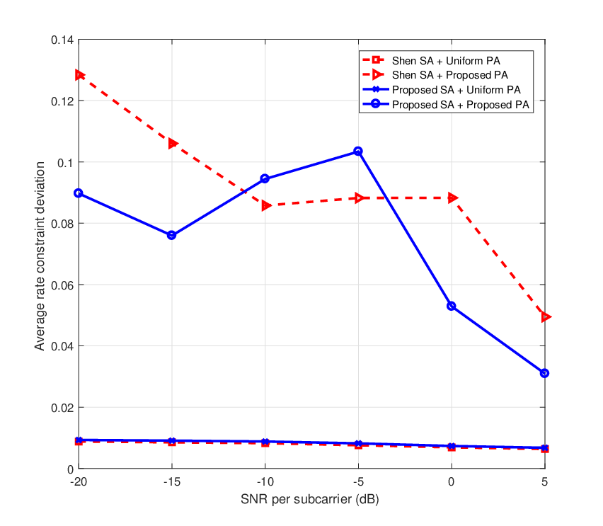
Besides the minimum rate, we also examine how well the rate-fairness constraint is adhered to. Fig. 4 shows the average rate-constraint deviation associated with the results in Fig. 3. In a low-SNR regime, the proposed PA has a relatively higher rate deviation since many subcarriers are assigned zero power. This leaves fewer subcarriers for transmission and hence, proportional-rate constraint is harder to satisfy. For higher-SNR regime, rate deviation is lower for all schemes. We also note that uniform PA gives lower rate deviation, but with lower sum rate. Thus, for a single-subcarrier-based assignment, our proposed SA combined with uniform PA performs generally well with lesser complexity.
It has been shown in [18] that, for users with the same target rates, the power consumed is minimal when the frequency reuse factor in the cell-edge area is 3. Therefore, for the multi-cell model, we assume a two-tier 19 cells with FRF-1 in the cell-centre area, and FRF-3 in the cell-edge area as shown in Fig. 2. We assume a total of 8 users per cell, uniformly distributed within a cell with 1-km radius. The propagation channel between a base station and a user follows a 3GPP TR 25.814 macro-cell system [17] with the parameters listed in Table I.
| Parameters | Values |
|---|---|
| Path loss | |
| FFT size | |
| Number of subcarriers | |
| Subcarrier spacing | kHz |
| BS transmit power | dBm |
| White noise power density | dBm/Hz |
| Intercell distant | km |
| Target BER |
In multi-cell setting, an important performance measure is the throughput of cell-edge users. In this simulation, the threshold is set to , and the average minimum throughput of cell-edge users in cell 1 obtained by various SA schemes at various chunk sizes are observed. We modify the single subcarrier-based SA algorithm proposed by [3] by replacing the rate of individual subcarrier in the algorithm with the average rate over a chunk. Results are shown in Fig. 5.

In all SA schemes, the throughputs are higher when FFR is used. The proposed SA is able to achieve the highest throughput for every chunk sizes. The difference in rate is pronounced when compared with static SA (the rate gain can be as large as 400%), but is not much when compared with the SA scheme modified from Shen et al.’s. As chunk size increases, the rate performance of the cell-edge users decreases. However, if chunk size is set to 4 or 8, the rate loss is not significant, but the complexity of SA can be reduced significantly. In Fig. 6, average rate constraint deviation of cell-edge users is also plotted. As expected, the deviation increases as chunk size increases. From the results, static SA has the highest deviation since the subcarriers are not adaptively assigned. The proposed SA and modified Shen et al.’s SA give much lower deviation and thus, fairer.

V Conclusions
In this work, we have proposed a chunk-based SA with PA and proportional-rate constraints for downlink OFDMA. Numerical results show that our proposed SA is able to obtain higher average minimum user’s achievable rate than existing schemes for both single-subcarrier-based and chunk-based assignment. In low SNR regime, user rate is more sensitive to PA and is at its highest with the proposed PA. However, in high SNR regime, user rate is more sensitive to SA and the rate obtained from different PA’s does not differ much as expected. With single-subcarrier-based assignment, uniform PA is sufficient to satisfy the rate constraints. However, with larger subcarrier chunks, proportional rates are more difficult to maintain with only SA. Thus, the proposed PA is required to reduce the effects of low-gain subcarriers within the chunk.
In a multi-cell scenario, a key parameter affecting system performance is the cell-centre radius. Determining the proper cell-centre radius is important, and must be done prior to SA. Results show that the proposed SA outperforms existing methods and that static SA has the worst performance among all SA’s. In addition, implementing FFR does improve the cell-edge user performance; however, as chunk size grows larger, the performance gain will be less noticeable.
The proposed scheme relies on the channel information, which can be accurately estimated at the mobiles and fed back to the base station. If estimation or feedback errors are significant, the performance will suffer. Adaptive resource allocation considered in this work is appropriate when channel is not very dynamic. Otherwise, the system will need to re-compute SA and PA more often. Effect of estimation or feedback error or channel’s fade rate on the performance can be analysed in future work.
Acknowledgements
This work was supported by Kasetsart University Research and Development Institute (KURDI) under the FY2016 Kasetsart University research grant and a joint funding from the Thailand Commission on Higher Education, Thailand Research Fund, and Kasetsart University under grant number MRG5580236.
References
- [1] J. Wisanmongkol and W. Santipach, “Chunk-based subcarrier assignment with power allocation and rate constraints for downlink ofdma,” in Proc. Int. Symp. on Commun. and Info. Technologies (ISCIT), Samui, Thailand, Sep. 2014, pp. 494–498.
- [2] W. Rhee and J. M. Cioffi, “Increasing in capacity of multiuser OFDM system using dynamic subchannel allocation,” in Proc. IEEE Vehicular Technol. Conf. (VTC2000-Spring), vol. 2, Tokyo, Japan, 2000, pp. 1085–1089.
- [3] Z. Shen, J. G. Andrews, and B. L. Evans, “Adaptive resource allocation in multiuser OFDM systems with proportional rate constraints,” IEEE Trans. Wireless Commun., vol. 4, no. 6, pp. 2726–2737, Nov 2005.
- [4] Z. Ren, S. Chen, B. Hu, and W. Ma, “Proportional resource allocation with subcarrier grouping in OFDM wireless systems,” IEEE Commun. Lett., vol. 17, no. 5, pp. 868–871, May 2013.
- [5] H. Zhu and J. Wang, “Chunk-based resource allocation in OFDMA systems–Part I: Chunk allocation,” IEEE Trans. Commun., vol. 57, no. 9, pp. 2734–2744, Sep 2009.
- [6] ——, “Chunk-based resource allocation in OFDMA systems–Part II: Joint chunk, power and bit allocation,” IEEE Trans. Commun., vol. 60, no. 2, pp. 499–509, Feb 2012.
- [7] A. S. Hamza, S. S. Khalifa, H. S. Hamza, and K. Elsayed, “A survey on inter-cell interference coordination techniques in OFDMA-based cellular networks,” IEEE Commun. Surveys Tuts., vol. 15, no. 4, pp. 1642–1670, March 2013.
- [8] T. S. Rappaport, Wireless Communications: Principles and Practice, 2nd ed. Prentice Hall, 2002.
- [9] G. Boudreau, J. Panicker, N. Guo, R. Chang, N. Wang, and S. Vrzic, “Interference coordination and cancellation for 4G networks,” IEEE Commun. Mag., vol. 47, no. 4, pp. 74–81, Apr. 2009.
- [10] Qualcomm Europe, “R1-050896 description and simulations of interference management technique for OFDMA based E-UTRA downlink evaluation,” Tech. Rep., August-September 2005.
- [11] I. Wong, Z. Shen, B. Evans, and J. Andrews, “A low complexity algorithm for proportional resource allocation in OFDMA systems,” in IEEE Workshop on Signal Processing Systems 2004, SIPS 2004, October 2004, pp. 1–6.
- [12] H. Lei, L. Zhang, X. Zhang, and D. Yang, “A novel multi-cell OFDMA system structure using fractional frequency reuse,” in Proc. IEEE International Symposium on Personal, Indoor and Mobile Radio Communications (PIMRC’07), Athens, Greece, September 2007, pp. 1–5.
- [13] T. Novlan, J. Andrews, I. Sohn, R. Ganti, and A. Ghosh, “Comparison of fractional frequency reuse approaches in OFDMA cellular downlink,” in 2010 IEEE Global Telecommunications Conference (GLOBECOM 2010), Miami, Florida, December 2010, pp. 1–5.
- [14] Z. Bharucha and H. Haas, “The distribution of path losses for uniformly distributed nodes in a circle,” Research Letters in Communications, vol. 2008, no. 4, pp. 1–4, January 2008.
- [15] J. Jang and K. B. Lee, “Transmit power adaptation for multiuser OFDM systems,” IEEE J. Sel. Areas Commun., vol. 21, no. 2, pp. 171–178, Feb 2003.
- [16] G. Song and Y. Li, “Cross-layer optimization for OFDM wireless networks-Part I: Theoretical framework,” IEEE Trans. Wireless Commun., vol. 4, pp. 614–624, March 2005.
- [17] 3GPP, “3GPP TR 25.814 physical layer aspects for evolved universal terrestrial radio access (UTRA),” 3GPP, Tech. Rep., September 2006.
- [18] N. Hassen and M. Assaad, “Optimal fractional frequency reuse (FFR) and resource allocation in multiuser OFDMA system,” in Proc. Int. Conf. Information and Communication Technologies ICICT’09, Karachi, August 2009, pp. 88–92.