All-Dielectric Metasurfaces Based on Cross-Shaped Resonators for Color Pixels with Extended Gamut
Abstract
Printing technology based on plasmonic structures has many advantages over pigment based color printing such as high resolution, ultra-compact size and low power consumption. However, due to high losses and broad resonance behavior of metals in the visible spectrum, it becomes challenging to produce well-defined colors. Here, we investigate cross-shaped dielectric nanoresonators which enable high quality resonance in the visible spectral regime and, hence, high quality colors. We numerically predict and experimentally demonstrate that the proposed all-dielectric nanostructures exhibit high quality colors with selective wavelengths, in particular, due to lower losses as compared to metal based plasmonic filters. This results in fundamental colors (RGB) with high hue and saturation. We further show that a large gamut of colors can be achieved by selecting the appropriate length and width of individual nanoantennas. Moreover, the proposed all-dielectric metasurface based color filters can be integrated with the well matured fabrication technology of electronic devices.
keywords
All-dielectric nanophotonics, color filter, plasmonics, structural colors, nanoantenna.With tremendous changes in nanotechnology over past few decades, it becomes possible to fabricate devices which promise to revolutionize many areas. Examples include ultra-thin planar lens Kildishev et al. (2013); Yu and Capasso (2014), optical sensing Adato et al. (2009); Liu et al. (2010), photo-voltaic devices Atwater and Polman (2010); Chen et al. (2012), non-fading colors James et al. (2016), and various holography based devices Almeida et al. (2016); Ni et al. (2013). In particular, color pixels using nanoparticles have gained significant attention in recent years because of several advantages over pigment based color printing techniques
like high resolution Tan et al. (2014), high contrast, everlasting colors, significant low power consumption, and recyclability of product Clausen et al. (2014). The concept of structural color printing is inspired by observations in nature, such as morpho butterflies, beetles, and the feathers of peacocks Srinivasarao (1999); Vukusic et al. (2001); Kinoshita et al. (2008); Gralak et al. (2001). However, these colors are highly sensitive to the variations in the angle of incidence, shape, and size of the nanostructure.
To make this plasmonics based structural technology
more mature, its angle dependency Wu et al. (2013); Højlund-Nielsen et al. (2014), sensitivity to polarization, and ease of fabrication must be taken into account. In recent years, many efforts have been done to study the aforementioned issue in plasmonic color printing Kumar et al. (2012); Roberts et al. (2014); Ellenbogen et al. (2012); Diest et al. (2013); Li et al. (2016); Duempelmann et al. (2015); Wang et al. (2016); Richner et al. (2016); Fan et al. (2017). Earlier, the most commonly used materials for plasmonic nanostructure based pixels have been gold and silver Ehrenreich and Philipp (1962); West et al. (2010). Gold has interband transition in the lower visible regime Ehrenreich and Philipp (1962), while silver is suitable for the entire visible range but is susceptible with the native oxide that spoils the stability of colors. Moreover, gold and silver are not economical for large scale integration. Aluminum is probably the most prominent candidate Gérard and Gray (2014). It is more robust and economical for
large-scale fabrication James et al. (2016). However, it shows lower quality (, broader) resonance in the visible spectrum than gold or silver, especially at 800 wavelength, where interband transition takes place. Ultimately, all these metal based plasmonic devices show significant losses within the visible spectrum.
On the other hand, all-dielectric metasurfaces can be a promising solution with significant advantages over metallic nanostructures such as high quality resonances and low intrinsic ohmic losses Paniagua-Domínguez et al. (2016); Bonod (2015); Jahani and Jacob (2016); Decker et al. (2015); Sautter et al. (2015); Li et al. (2016); Moitra et al. (2015); Liu et al. (2014); Hegde and Panse (2016). Silicon based all-dielectric devices have been reported for local manipulation by wavefronts, such as beam diversion, vortex plates and light focusing using meta-lenses Shalaev et al. (2015); Decker et al. (2015); Staude et al. (2013); Lin et al. (2014); Arbabi et al. (2015). The advantages of nanodisks are high refractive index and ease of fabrication with well established CMOS technology. Interestingly, the high refractive index allows to manipulate by magnetic and electric components of light simultaneously. In the case of metal based nanoantennas, absorption losses can be significant at visible spectrum, while interaction with magnetic component of the incident beam requires more complex shapes. Recently, an investigation has been conducted to demonstrate the possibility of using silicon-aluminum hybrid nanodisks Yue et al. (2016); Shrestha et al. (2015) to create colors of high quality. Silicon nanoparticles were proposed as a valuable alternative to plasmonic nanoantennae for the design of color pixels Cao et al. (2010); Proust et al. (2016); Zhao et al. (2016); Hegde and Panse (2016). However, the potential
of all-dielectric resonance structures is presently very far from being fully estimated and exploited.
In this work, we propose a systematic approach to build color filters by using advantages of cross-shaped nanoresonators, which are closely spaced to each other to create a metasurface. Recently reported numerical studies of the nanocross geometry Hegde and Panse (2016) have indicated that a broader gamut of colors is possible in comparison to simpler shapes like the cylinder (disk). The main goal is to obtain a high quality (narrow) resonance throughout the visible spectrum that enables an extended gamut with colors of high purity. It is known that nanostructures of different shapes typically offer an opportunity to excite individual electric type and magnetic type Mie resonances, or both resonances simultaneously Kuznetsov et al. (2012). In fact, it has been demonstrated that by tuning the aspect ratio carefully, one can overlap both resonances to achieve near unity transmission Staude et al. (2013). In this paper, the all-dielectric metasurfaces are used in reflection mode. A very confined energy is concentrated within the structure due to the high quality of the used Mie resonances.
The main hypothesis that we follow here is based on the expectation that a proper manipulation by the selected Mie resonances may enable desired improvements of the resulting resonance quality owing to better confinement of resonance fields and, simultaneously, removal of secondary (unwanted) spectral features, so that enrichment of colors can be achieved. We decided in favor of cross-shaped nanoresonators as building elements, which are expected to be suitable Hegde and Panse (2016) for achievement of the goals of this study. Each of them is made of two identical orthogonal rectangle-shaped nanoantennas. In this case, resonances are governed by cross-shaped nanoantennas and thus, colors can be controlled all three geometrical parameters of individual nanoantennas. This gives a new degree of freedom as compared to the nanodisks, that is highly demanded for efficient optimization. Using the suggested approach, we predict by simulations and confirm experimentally that one can easily achieve a high quality resonance for the entire visible spectrum by carefully choosing the length and width of the cross-shaped nanoresonators.
1 Results

Let us start from the general geometry and basic operation principles of the proposed devices. Figure 1(a) presents the perspective view of the proposed all-dielectric metasurface together with some details of geometry. The cross-shaped nanoresonators are deposited on top of the quartz substrate (see Methods of fabrication). The height of nanoantennae is selected as 140 (in subwavelength range). Figure 1(b) represents the top view of SEM image of the device. A 45∘ cross section view is also added in the inset for the same fabricated device. For the studied structure, extinction cross section spectrum is presented in Fig. 1(c). Two resonance peaks are observed at 465 and 520. They can be tuned throughout the visible range by changing the length-to-width aspect ratio of individual rectangle-shaped nanoantennas. The nanoresonator dimensions have been optimized to excite these two resonances as close as possible but without a full overlapping. In addition, the criterium of minimizing unwanted spectral features has been applied in order to obtain more gradual behavior in the working spectral range. As follows from the obtained simulation results, optimization yields a resonance range that is narrower and, thus, corresponds to a resonance of higher quality, as compared to the case of cross-shaped nanoantennae, see Fig. 1(c). We have also compared the simulated reflectance spectra for the metal and based structures at the same dimensions [see Fig. 1(c), inset]. These results confirm that the metal nanostructure features broader resonances than the engineered one. An important advantage of cross-shaped nanoantennae is that they preserve the polarization independence. As an example, Fig. 1(d) presents the simulated reflectance spectrum for the entire range of polarization angle variation and entire wavelength range considered. The obtained results confirm that there is no change in the reflectance spectrum when the polarization angle is varied.
Since a specific color results from resonant interaction of light with nanoresonators, it can be obtained from adjustment of geometrical parameters that properly affect spectral locations and properties of Mie resonances. The possibility of obtaining multiple colors with the aid of metasurfaces like that in Fig. 1(a) and (b) is demonstrated in Fig. 2. The length and width of rectangle-shaped nanoantennae are simultaneously linearly scaled in order to tune the electric and magnetic type resonances in the entire visible spectrum from 400 to 700, as shown in Fig. 2(a) for . A commercial-grade simulator based on the finite-difference time-domain method Lum () is used to perform the calculations. They are conducted for a unit cell with periodic boundary conditions, and varied lattice constant from 250 to 350, by keeping the periodicity in the subwavelength range (see Methods, Simulation). Each spectral zone in Fig. 2(a) corresponds to a specific color. It is clearly seen that the electric and magnetic type resonances can be tuned through the entire visible wavelength spectrum, as desired. Conversion of reflectance spectra into colors on CIE1931 chromaticity diagram can be performed, in the general case, by using an open source Python program col (). The results of conversion of the spectra shown in Fig. 2(a) are presented in Fig. 2(b). Generally, a higher quality of resonances corresponds to a better approaching to the boundaries of the chromaticity diagram and, hence, enable higher quality and wider gamut of colors. Complete details about color visualization using reflectance spectra are given in supplementary information under section color representation from reflectance spectra.
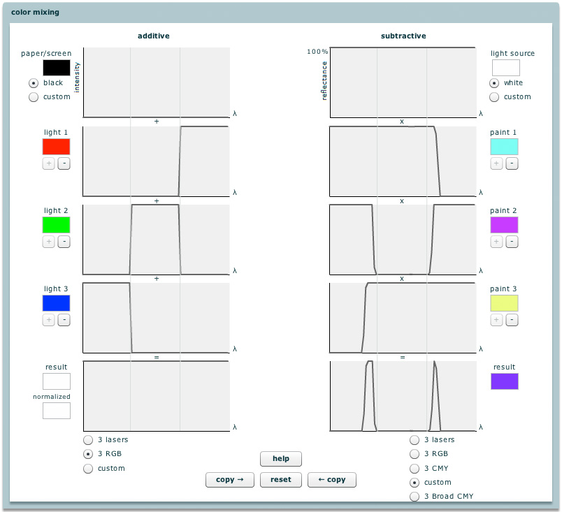
By operating the metasurface in reflection mode, a broad spectrum of colors for highly selective wavelengths (, high quality colors) can be obtained. In principle, colors can be generated by using either additive or subtractive approach col (). Here, we have used the additive approach. Ideally, the reflection spectrum must be as narrow as possible in order to generate a very specific color. A narrower resonance represents a more specific wavelength color, whereas the amplitude of the peak decides the saturation level of the color. With the aid of high quality narrow resonances, we improve the approaching to the boundaries of CIE-1931 chromaticity diagram, so a color of higher quality and a wider gamut of colors can be obtained, as desired. We experimentally found that different colors can be obtained at different values of period (, lattice constant), which correspond to the scaled length and width of the nanoantenna, see Fig. 2(c). Each square in Fig. 2(c) corresponds to a unique set of geometrical parameters. The lowest series of the squares shown here corresponds to the structures, for which reflectance spectra are presented in Fig. 2(a). Thus, the resonance region corresponds to different colors at different values of , see Fig. S4 in supplementary information. This dependence occurs owing to the coupling of resonance fields of nanoresonators. The use of larger values of allows us to create a richer variety of colors, as we have more choices to increase the length and width. We have observed different colors under optical microscope due to variations in lattice constant from 250 to 350, see Fig. 2(c). The lattice constant was increased here by a reasonable increment of 20 to make it feasible for fabrication process. Although it might be hard to distinguish between the highly saturated colors in Fig. 2(c), the reflectance spectra in Fig. 2(a) and the corresponding CIE-1931 chromaticity diagram in Fig. 2(b) give us a clear picture about it. In fact, a color gamut can be possible by making a matrix between the scaled lengths and widths.
The fact that two resonances, which are observed in Fig. 2(a) at different values of and , are closely spaced makes fabrication of a particular color possible, that is unlikely in case of metal based plasmonic structures, because they show a broad resonance. Moreover, it is possible to create a selective wavelength color due to sharp resonances, particularly in the lower part of the visible spectrum.
It is observed in Fig. 2(a) that as we increase the size of cross-shaped resonators some additional Mie resonances are also excited, in coincidence with the predictions based on the simulation results. These resonances reduce the hue and saturation of red color, because of mixing contribution of different frequencies. So the red color seems to be the most difficult one to fabricate. Below, we will show that in spite of the above-mentioned difficulties the suggested structure allows us creating fairly red colors by carefully adjusting the values of , , and . Thanks to this adjustment, the unwanted effect of higher-order resonances can be minimized.

The three primary colors (RGB) represent the fundamental unit for color printing technology. All the other colors in the RGB gamut can be derived by mixing the primary colors appropriately. Figure 3 presents the results of a detailed experimental demonstration of the suggested devices in the form of pixels. A dual characterization is done to ensure the results by measuring the reflectance spectra of the samples with the aid of a home-made customized setup and observing the colors directly under optical microscope (see Methods, Optical characterization). Figure 3(a) shows the experimental and simulated reflectance spectra for highly saturated primary colors. These results show good agreement with each other. Figure 3(b) shows the SEM images obtained at different sizes of nanoantennas. Insets are added to the SEM images to show the corresponding colors visible under optical microscope, which are associated with the different sizes of the cross-shaped nanoresonators. Finally, these three primary colors are fabricated in a form of pixel, being the main component of any display device. The size of each square block is 50. Details of the used fabrication method are given at the end of the paper. The optical microscope images shown in Fig. 3(c) confirm the quality of highly saturated primary colors, which is an important advantage of the suggested all-dielectric metasurface based pixels over the existing plasmonics devices. A CIE 1931 chart is used to represent the simulated and experimental spectra of the primary colors, see Fig. 3(d). One can see a very small shift in color spectrum, which might come from fabrication imperfections. It is noticeable that there is good coincidence between two sets of experimental results.

2 Conclusion
Polarization insensitive all-dielectric metasurfaces based on 2D arrays of cross-shaped nanoresonators have been proposed to realize color filters with extended gamut for the entire visible spectrum. A numerical investigation has been carried out that demonstrates the principal possibility of obtaining high-purity colors by means of optimization of resonance properties, which can be realized by a relatively simple adjustment of the structural parameters. The role of existence and properties of the dual resonance, which is achieved at a partial overlapping of electric type and magnetic type resonances, and that of suppression of unwanted spectral features in the obtaining of these advancements have been clarified. The utilized resonances can be tuned by changing the length-to-width aspect ratio of individual rectangle-shaped nanoantennas. This concept has been used to design and fabricate the color filters. Our simulation results reasonably agree with the experimental ones. Some differences should be noticed that may be connected with fabrication complexity of the structure. The experimentally demonstrated possibility of obtaining high quality (narrow) resonances, which enable high quality colors, is the most important result of this work. We have demonstrated the wide variety of colors for different periodicity and size of cross-shaped nanoresonators. Additionally, we have demonstrated the primary colors painting in the form of pixels. These colors show high saturation and hue value. In fact, our device is capable to produce a large panel color in the visible regime with strong spectral selectivity, provided that the nanoantenna aspect ratio is properly chosen. By carefully controlling the balance between desired and unwanted Mie resonances, one can further optimize the color filter, especially in dark zone of red color. Since the (amorphous-) is the most suitable material for large-scale fabrication with the existing technology, it can potentially be used for making low-cost, eco-friendly, high quality, long lasting painting possible for mass production in the future.
3 Methods
Simulations. We have used Lumerical FDTD solver Lum () to study metasurfaces comprising the cross-shaped nanoresonators on a dielectric substrate. The materials used for substrate and cross-shaped nanoresonators are and , respectively. The material parameters are taken from default the material library of the used software. A plane wave ranging from 400 to 700 is illuminated from the top of the structure. Periodic boundary conditions are used in the unit cell along and directions. Perfect matching layer (PML) boundary conditions were used in the directions to avoid any reflection. The reflectance spectra are simulated by considering a unit cell (one cross-shaped nanoresonator on substrate) with periodic boundary conditions in and directions.
Device fabrication. A piranha cleaned quartz sample (275 thick) is used to fabricate the device. We have deposited a thin layer of 140 amorphous using ICPCVD tool at 300Celsius with 150W added microwave power. A single-layer PMMA photoresist is used for patterning cross-shaped nanoresonators by using Raith 150-Two EBL tool. An electronic mask is designed using an open source Python program. The exposed sample is developed using MIBK-IPA (1:3) and an IPA solution for 45 and 15, respectively. A thin layer of metal (5 Cr as adhesion layer and 40 Au) is deposited to transfer the pattern on metal layer for lift-off process using four target evaporators. After lift-off, the sample is etched using plasma asher to get the final pattern. A process flow chart with step by step details is available in supplementary information.
Optical characterization. A dual optical characterization is done to ensure the results. The sample is placed under Olympus optical microscope and illuminated with white light without filter. The colors can be directly seen under optical microscope. The reflectance spectra are measured using a home-made customized setup. A HL 2000 halogen lamp source is coupled with an optical fiber to illuminate the sample in the visible range, , from 400 to 700. A 50 objective lens with is used to get tight focusing of light on the sample. The reflectance spectra are measured using the same objective lens. All the collected data are normalized with respect to the bare quartz sample. A Nikon camera attached with assembly is used to take the photograph of the illuminated area.
References
- Kildishev et al. (2013) Kildishev, A. V.; Boltasseva, A.; Shalaev, V. M. Planar photonics with metasurfaces. Science 2013, 339, 1232009.
- Yu and Capasso (2014) Yu, N.; Capasso, F. Flat optics with designer metasurfaces. Nat. Materials 2014, 13, 139–150.
- Adato et al. (2009) Adato, R.; Yanik, A. A.; Amsden, J. J.; Kaplan, D. L.; Omenetto, F. G.; Hong, M. K.; Erramilli, S.; Altug, H. Ultra-sensitive vibrational spectroscopy of protein monolayers with plasmonic nanoantenna arrays. Proc. Nat. Acad. Sci. 2009, 106, 19227–19232.
- Liu et al. (2010) Liu, N.; Mesch, M.; Weiss, T.; Hentschel, M.; Giessen, H. Infrared perfect absorber and its application as plasmonic sensor. Nano Lett. 2010, 10, 2342–2348.
- Atwater and Polman (2010) Atwater, H. A.; Polman, A. Plasmonics for improved photovoltaic devices. Nat. Materials 2010, 9, 205–213.
- Chen et al. (2012) Chen, X.; Jia, B.; Saha, J. K.; Cai, B.; Stokes, N.; Qiao, Q.; Wang, Y.; Shi, Z.; Gu, M. Broadband enhancement in thin-film amorphous silicon solar cells enabled by nucleated silver nanoparticles. Nano Lett. 2012, 12, 2187–2192.
- James et al. (2016) James, T. D.; Mulvaney, P.; Roberts, A. The plasmonic pixel: large area, wide gamut color reproduction using aluminum nanostructures. Nano Lett. 2016, 16, 3817–3823.
- Almeida et al. (2016) Almeida, E.; Bitton, O.; Prior, Y. Nonlinear metamaterials for holography. Nat. Commun. 2016, 7, 12533.
- Ni et al. (2013) Ni, X.; Kildishev, A. V.; Shalaev, V. M. Metasurface holograms for visible light. Nat. Commun. 2013, 4, 3807.
- Tan et al. (2014) Tan, S. J.; Zhang, L.; Zhu, D.; Goh, X. M.; Wang, Y. M.; Kumar, K.; Qiu, C.-W.; Yang, J. K. Plasmonic color palettes for photorealistic printing with aluminum nanostructures. Nano Lett. 2014, 14, 4023–4029.
- Clausen et al. (2014) Clausen, J. S.; Højlund-Nielsen, E.; Christiansen, A. B.; Yazdi, S.; Grajower, M.; Taha, H.; Levy, U.; Kristensen, A.; Mortensen, N. A. Plasmonic metasurfaces for coloration of plastic consumer products. Nano Lett. 2014, 14, 4499–4504.
- Srinivasarao (1999) Srinivasarao, M. Nano-optics in the biological world: beetles, butterflies, birds, and moths. Chemical Rev. 1999, 99, 1935–1962.
- Vukusic et al. (2001) Vukusic, P.; Sambles, J.; Lawrence, C.; Wootton, R. Structural colour: now you see it —now you don’t. Nature 2001, 410, 36–36.
- Kinoshita et al. (2008) Kinoshita, S.; Yoshioka, S.; Miyazaki, J. Physics of structural colors. Repor. Prog. Phys. 2008, 71, 076401.
- Gralak et al. (2001) Gralak, B.; Tayeb, G.; Enoch, S. Morpho butterflies wings color modeled with lamellar grating theory. Opt. Express 2001, 9, 567–578.
- Wu et al. (2013) Wu, Y.-K. R.; Hollowell, A. E.; Zhang, C.; Guo, L. J. Angle-insensitive structural colours based on metallic nanocavities and coloured pixels beyond the diffraction limit. Sci. Rep. 2013, 3, 1194.
- Højlund-Nielsen et al. (2014) Højlund-Nielsen, E.; Weirich, J.; Nørregaard, J.; Garnaes, J.; Mortensen, N. A.; Kristensen, A. Angle-independent structural colors of silicon. J. Nanophoton. 2014, 8, 083988–083988.
- Kumar et al. (2012) Kumar, K.; Duan, H.; Hegde, R. S.; Koh, S. C.; Wei, J. N.; Yang, J. K. Printing colour at the optical diffraction limit. Nat. Nanotechnol. 2012, 7, 557–561.
- Roberts et al. (2014) Roberts, A. S.; Pors, A.; Albrektsen, O.; Bozhevolnyi, S. I. Subwavelength plasmonic color printing protected for ambient use. Nano Lett. 2014, 14, 783–787.
- Ellenbogen et al. (2012) Ellenbogen, T.; Seo, K.; Crozier, K. B. Chromatic plasmonic polarizers for active visible color filtering and polarimetry. Nano Lett. 2012, 12, 1026–1031.
- Diest et al. (2013) Diest, K.; Liberman, V.; Lennon, D. M.; Welander, P. B.; Rothschild, M. Aluminum plasmonics: optimization of plasmonic properties using liquid-prism-coupled ellipsometry. Opt. Express 2013, 21, 28638–28650.
- Li et al. (2016) Li, Z.; Clark, A. W.; Cooper, J. M. Dual color plasmonic pixels create a polarization controlled nano color palette. ACS Nano 2016, 10, 492–498.
- Duempelmann et al. (2015) Duempelmann, L.; Casari, D.; Luu-Dinh, A.; Gallinet, B.; Novotny, L. Color rendering plasmonic aluminum substrates with angular symmetry breaking. ACS Nano 2015, 9, 12383–12391.
- Wang et al. (2016) Wang, L.; Ng, R. J. H.; Safari Dinachali, S.; Jalali, M.; Yu, Y.; Yang, J. K. Large area plasmonic color palettes with expanded gamut using colloidal self-assembly. ACS Photonics 2016, 3, 627–633.
- Richner et al. (2016) Richner, P.; Galliker, P.; Lendenmann, T.; Kress, S. J.; Kim, D. K.; Norris, D. J.; Poulikakos, D. Full-spectrum flexible color printing at the diffraction limit. ACS Photonics 2016, 3, 754–757.
- Fan et al. (2017) Fan, J.; Wu, W.; Chen, Z.; Zhu, J.; Li, J. Three-dimensional cavity nanoantennas with resonant-enhanced surface plasmons as dynamic color-tuning reflectors. Nanoscale 2017,
- Ehrenreich and Philipp (1962) Ehrenreich, H.; Philipp, H. R. Optical properties of Ag and Cu. Phys. Rev. 1962, 128, 1622–1629.
- West et al. (2010) West, P. R.; Ishii, S.; Naik, G. V.; Emani, N. K.; Shalaev, V. M.; Boltasseva, A. Searching for better plasmonic materials. Laser & Photonics Rev. 2010, 4, 795–808.
- Gérard and Gray (2014) Gérard, D.; Gray, S. K. Aluminium plasmonics. J. Phys. D: Appl. Phys. 2014, 48, 184001.
- Paniagua-Domínguez et al. (2016) Paniagua-Domínguez, R.; Yu, Y. F.; Miroschnichenko, A. E.; Krivitsky, L. A.; Fu, Y. H.; Valuckas, V.; Gonzaga, L.; Toh, Y. T.; Kay, A. Y. S.; Luk’yanchuk, B.; Kuznetsov, A. I. Generalized Brewster effect in dielectric metasurfaces. Nat. Commun. 2016, 7, 10362.
- Bonod (2015) Bonod, N. Silicon photonics: Large-scale dielectric metasurfaces. Nature Materials 2015, 14, 664–665.
- Jahani and Jacob (2016) Jahani, S.; Jacob, Z. All-dielectric metamaterials. Nat. Nanotechnol. 2016, 11, 23–36.
- Decker et al. (2015) Decker, M.; Staude, I.; Falkner, M.; Dominguez, J.; Neshev, D. N.; Brener, I.; Pertsch, T.; Kivshar, Y. S. High-efficiency dielectric Huygens′ surfaces. Adv. Opt. Mat. 2015, 3, 813–820.
- Sautter et al. (2015) Sautter, J.; Staude, I.; Decker, M.; Rusak, E.; Neshev, D. N.; Brener, I.; Kivshar, Y. S. Active tuning of all-dielectric metasurfaces. ACS Nano 2015, 9, 4308–4315.
- Li et al. (2016) Li, J.; Verellen, N.; Vercruysse, D.; Bearda, T.; Lagae, L.; Van Dorpe, P. All-dielectric antenna wavelength router with bidirectional scattering of visible light. Nano Lett. 2016, 16, 4396–4403.
- Moitra et al. (2015) Moitra, P.; Slovick, B. A.; Li, W.; Kravchencko, I. I.; Briggs, D. P.; Krishnamurthy, S.; Valentine, J. Large-scale all-dielectric metamaterial perfect reflectors. ACS Photonics 2015, 2, 692–698.
- Liu et al. (2014) Liu, S.; Sinclair, M. B.; Mahony, T. S.; Jun, Y. C.; Campione, S.; Ginn, J.; Bender, D. A.; Wendt, J. R.; Ihlefeld, J. F.; Clem, P. G.; Wright, J. B.; Brener, I. Optical magnetic mirrors without metals. Optica 2014, 1, 250–256.
- Hegde and Panse (2016) Hegde, R. S.; Panse, K. S. Design and optimization of ultrathin spectral filters based on silicon nanocross antenna arrays. J. Nanophoto. 2016, 10, 026030–026030.
- Shalaev et al. (2015) Shalaev, M. I.; Sun, J.; Tsukernik, A.; Pandey, A.; Nikolskiy, K.; Litchinitser, N. M. High-efficiency all-dielectric metasurfaces for ultracompact beam manipulation in transmission mode. Nano Lett. 2015, 15, 6261–6266.
- Staude et al. (2013) Staude, I.; Miroshnichenko, A. E.; Decker, M.; Fofang, N. T.; Liu, S.; Gonzales, E.; Dominguez, J.; Luk, T. S.; Neshev, D. N.; Brener, I.; Kivshar, Y. Tailoring directional scattering through magnetic and electric resonances in subwavelength silicon nanodisks. ACS Nano 2013, 7, 7824–7832.
- Lin et al. (2014) Lin, D.; Fan, P.; Hasman, E.; Brongersma, M. L. Dielectric gradient metasurface optical elements. Science 2014, 345, 298–302.
- Arbabi et al. (2015) Arbabi, A.; Horie, Y.; Bagheri, M.; Faraon, A. Dielectric metasurfaces for complete control of phase and polarization with subwavelength spatial resolution and high transmission. Nat. Nanotechnol. 2015, 937–943.
- Yue et al. (2016) Yue, W.; Gao, S.; Lee, S.-S.; Kim, E.-S.; Choi, D.-Y. Subtractive color filters based on a silicon-aluminum hybrid-nanodisk metasurface enabling enhanced color purity. Sci. Rep. 2016, 6, 29756.
- Shrestha et al. (2015) Shrestha, V. R.; Lee, S.-S.; Kim, E.-S.; Choi, D.-Y. Polarization-tuned dynamic color filters incorporating a dielectric-loaded aluminum nanowire array. Sci. Rep. 2015, 5, 12450.
- Cao et al. (2010) Cao, L.; Fan, P.; Barnard, E. S.; Brown, A. M.; Brongersma, M. L. Tuning the color of silicon nanostructures. Nano Lett. 2010, 10, 2649–2654.
- Proust et al. (2016) Proust, J.; Bedu, F.; Gallas, B.; Ozerov, I.; Bonod, N. All-dielectric colored metasurfaces with silicon Mie resonators. ACS Nano 2016, 10, 7761–7767.
- Zhao et al. (2016) Zhao, W.; Liu, B.; Jiang, H.; Song, J.; Pei, Y.; Jiang, Y. Full-color hologram using spatial multiplexing of dielectric metasurface. Opt. Lett. 2016, 41, 147–150.
- Kuznetsov et al. (2012) Kuznetsov, A. I.; Miroshnichenko, A. E.; Fu, Y. H.; Zhang, J.; Luk’yanchuk, B. Magnetic light. Sci. Rep. 2012, 2, 00492.
- (49) http://www.lumerical.com/tcad-products/fdtd/.
- (50) http://colour.readthedocs.io/en/latest.
- (51) https://graphics.stanford.edu/courses/cs178/applets/custom-subtractive-too-wide.jpg.