Feedback Control of the Pusher-Slider System: A Story of Hybrid and Underactuated
Contact Dynamics
Abstract
This paper investigates real-time control strategies for dynamical systems that involve frictional contact interactions. Hybridness and underactuation are key characteristics of these systems that complicate the design of feedback controllers. In this research, we examine and test a novel feedback controller design on a planar pushing system, where the purpose is to control the motion of a sliding object on a flat surface using a point robotic pusher. The pusher-slider is a simple dynamical system that retains many of the challenges that are typical of robotic manipulation tasks.
Our results show that a model predictive control approach used in tandem with integer programming offers a powerful solution to capture the dynamic constraints associated with the friction cone as well as the hybrid nature of the contact. In order to achieve real-time control, simplifications are proposed to speed up the integer program. The concept of Family of Modes (FOM) is introduced to solve an online convex optimization problem by selecting a set of contact mode schedules that spans a large set of dynamic behaviors that can occur during the prediction horizon. The controller design is applied to stabilize the motion of a sliding object about a nominal trajectory, and to re-plan its trajectory in real-time to follow a moving target. We validate the controller design through numerical simulations and experimental results on an industrial ABB IRB 120 robotic arm.
1 INTRODUCTION
Humans manipulate objects within their hands with impressive agility and ease. While doing so, they also make many and frequent mistakes from which they recover seamlessly. The mechanical complexity of the human hand along with its array of sensors sure play an important role. However, despite recent advances in the design of complex robotic hands [1, 2, 3] and sensory equipment (tactile sensors, vision markers, proximity sensors, etc. [4, 5]), autonomous robotic manipulation remains far from human skill at manipulating with their hands or teleoperating robotic interfaces.
We argue that this gap in performance can largely be attributed to robots’ inability to use sensor information for real-time control purposes. Whereas humans effectively process and react to information from tactile and vision sensing, robot manipulators are most often programmed in an open-loop fashion, incapable of adapting or correcting their motion. With the recent development of sensing equipment, the question remains: how should robots use sensed information?
This work is concerned with the challenges involved in closing the loop through contact in robotic manipulation. To the knowledge of the authors, a general feedback controller design methodology is still lacking in the field of robotic manipulation, which is essential for robots to be aware and reactive to contact. In this article, we focus our attention on dexterous manipulation tasks, where the manipulated object moves relative to the robot’s end effector.
In this article we examine and test a feedback controller design for the pusher-slider system, where the purpose is to control the motion of a sliding object on a flat surface using a point pusher. The pusher-slider system is a simple dynamical system that incorporates several of the challenges that are typical of robotic manipulation tasks. In particular, we are concerned with two main challenges:
- 1.
It is a hybrid dynamical system that exhibits different contact modes between the pusher and slider (e.g. separation, sticking, sliding up, and sliding down). Transitions between these modes result in discontinuities in the dynamics, which complicate controller design.
- 2.
It is an underactuated system where the contact forces from the pusher acting on the sliding object are constrained to remain inside the friction cone. These constraints on the control inputs lead to a dynamical system where the velocity control of the pusher is not sufficient to produce an arbitrary acceleration of the slider. Ultimately, the controller must reason about finite horizon trajectories and not just instantaneous actuation.
The purpose of this article is to develop a feedback controller design that can handle both challenges described above. Our results show that a model predictive control approach used in tandem with integer programming offers a powerful solution to capture the dynamic constraints associated with the friction cone as well as the hybrid nature of contact. In order to achieve real-time control, simplifications are proposed to speed up the integer program. The concept of Family of Modes (FOM) is proposed to solve an online convex optimization problem by simulating the dynamical system forward using a set (i.e., family) of mode schedules that are identified as being key. Numerical simulations and experimental results, performed using an industrial robotic manipulator to push the sliding object and a Vicon system to track its pose, show that the FOM methodology yields a feedback controller design that can be implemented in real-time and stabilize the motion of a slider through a single contact point about a nominal trajectory.
2 RELATED WORK
Historically, grasping and in-hand dexterous manipulation have been two main focuses of robotic manipulation research. In grasping, conventional control approaches first search for the location of grasp contact points that yield some form of geometric closure on the object [6], then close the gripper either blindly or with force control, and finally treat the object as a rigid extension of the robotic arm. In-hand dexterous manipulation was first explored by Salisbury and Craig [7] for dynamic in-hand motion. The controller design techniques presented in the in-hand dexterous literature typically apply to complex robotic hands and rely on the gripper and the manipulated objects to stick together at the contact points.
Dafle et al. [8, 9] demonstrated that simple robotic hands can be used to perform fast and effective regrasp strategies by using the robotic arm and the environment as an external source of actuation. When performing these regrasp strategies, the contact interactions are not limited to sticking contact but also necessarily exploit sliding motion. The control actions proposed by [8, 9] require offline trajectory planning and rely on accurate contact models.
Recently, Posa et al. [10] proposed to apply trajectory optimization tools to determine the motion of the robot and the manipulated object by including contact reaction forces along with motions as decision variables in a large optimization program. This method has been shown to be effective for path planning of high degree of freedom systems undergoing contact interactions. This paper shares the motivation of including contact forces as decision variables as part of an optimization program.
The application of feedback control strategies to discontinuous contact dynamical systems is a relatively unexplored field of research. Tassa and al. [11, 12] have achieved remarkable simulation results by using smoothed contact models in an optimal control framework, and a similar approach has been proposed by Stewart and Anitescu [13]. These methods contrast to the approach explored in this paper, where hybridness of contact is considered explicitly.
With regard to the pusher-slider system, Mason [14] presented an early study of the mechanics of planar pushing. This theory has been applied to the design of controllers that achieve stable pushing [15], which offers the advantage of operating without sensor feedback by acting as an effective grasp. In [16], this theory is expanded to a tactile feedback based controller for the case of a point pusher-slider system.
3 CHALLENGES OF CONTROL THROUGH CONTACT
The aim of this work is to accurately control the motion of objects through contact. Two major difficulties are typical of these systems: hybridness and underactuation.
3.1 Hybridness
When in contact, object and manipulator can interact in different manners. For example, the object can slip within the fingers of the gripper, the gripper can throw the object in the air or perform pick and place maneuvers, etc. These manipulation actions correspond to different contact interaction modes, namely sliding, separation, and sticking. The hybridness associated with the transitions between modes can result in a non-smooth dynamical system. This complicates the design of feedback controllers as the vast majority of standard control techniques rely on smoothness of the dynamical model.
In many applications involving hybrid dynamical systems, this difficulty is overcome by setting the mode scheduling of the controller offline or using on-board sensing to detect mode transitions. For example, in the locomotion community, it is common to transition between two feedback controllers as the robot switches from a stance phase to an aerial phase [17], as in Fig. 1.

For robotic manipulation tasks, the mode scheduling is often not known a priori and can be challenging to predict. In such cases, we must rely on the controller to decide during execution what interaction mode is most beneficial to the task. Figure 2 illustrates the example of picking a book from a shelf. The hand interacts with the book in a complex manner. It is difficult to say when fingers and palm stick or slide, but those transitions not only happen, but are necessary to pick the book. Likely the hand initially sticks to the book and drags it backwards exploiting friction. Then, the thumb and fingers swiftly slide to regrasp the book. Finally, the book is retrieved from the shelf using a stable grasp. For such manipulation tasks where the motion is not periodic, determining a fixed mode sequencing strategy is not obvious and likely impractical. Errors during execution will surely require that the mode sequencing be altered.

3.2 Underactuation
Underactuation is due to the fact that contact interactions can only transmit a limited set of forces and torques to the object. As such, the controller must reason only among the forces that can physically be realized. For example, the normal forces commanded should be positive, as contact interactions can only “push” and cannot “pull.” In order to achieve this, it is required to explicitly integrate the physical constraints associated with contact interactions in the controller design. A second important consequence of underactuation is that the controller must be capable of reasoning about future not just instantaneous actuation since the forces required to drive the task in the direction of the goal might not be feasible at the current instant. The controller must reason on a finite horizon.
4 PUSHER-SLIDER SYSTEM
In this article, we study the pusher-slider system, a simple nonprehensile manipulation task where the goal is to control the motion of a sliding object (slider) through a single frictional contact point (pusher). The pusher-slider system is a useful test case dynamical system for controller design where actuation arises from friction.
4.1 Kinematics

Consider the system in Fig. 3. The pose of the slider is where and denote the cartesian coordinates of the center of mass of the slider and its orientation relative to the inertial reference frame . The position of the pusher relative to point resolved in is . Figure 3 shows the kinematics of the slider subject to contact interactions with a single point of contact robotic pusher.
4.2 Quasi-Static Approximation
During contact interactions, two external forces are exerted on the slider: the generalized frictional force applied by the pusher on the slider (denoted ) and the generalized frictional force applied by the ground on the sliding object (denoted ). Applying Newton’s second law in the - plane yields the motion equations
| (1) |
where denotes the inertia matrix of the system. The quasi-static assumption suggests that at low velocities, frictional contact forces dominate and inertial forces do not have a decisive role in determining the motion of the slider. Under this assumption, the applied frictional force by the pusher is of equal magnitude and opposite direction to the ground planar frictional force (i.e., ). This quasi-static assumption leads to a simplified analysis of the motion of a sliding object using a single point of contact robotic pusher. Note that including the term does not complicate the controller design and could easily be integrated into the control formulation presented in Section 5. The resulting controller from a dynamic analysis yields a mapping between the motion of the slider to the reaction forces applied on the object. In contrast, the quasi-static assumption leads to a direct mapping between the motion of the slider and the motion of the pusher. This proved desirable from an experimental implementation standpoint using a position controlled robotic manipulator.
The motion equations of the pusher-slider system are formulated in [16] assuming a quasi-static formulation with a uniform pressure distribution. Prior to presenting these motion equations, it is necessary to review two important concepts of frictional contact interactions: the limit surface and the motion cone.
4.3 Limit Surface
The limit surface is a useful geometric representation which, under the quasi-static assumption, maps the applied frictional force on an object to its resulting velocity. First introduced in [19], the limit surface is defined as a convex surface which bounds the set of all possible frictional forces and moments that can be sustained by frictional interface. In this paper, we use the ellipsoidal approximation to the limit surface [20], where the semi-principal axes are given by , , and defined by and where is the coefficient of friction between the object and the ground, is the mass of the object, is the gravitational acceleration, is the surface area of the object exposed to friction, and denotes the position of relative to the origin of .
4.4 Motion Cone

Depending on the direction of motion of the pusher, different contact interaction modes can arise between the pusher and the slider. The motion cone [14], shown in Fig. 4, is useful to determine if a given velocity of the pusher will result in sticking or sliding behavior between the pusher and the slider. Each boundary of the motion cone is constructed by mapping the resulting velocity of the slider at the contact point when subject to a frictional force that lies on a boundary of the friction cone. It can be shown using the ellipsoidal approximation to the limit surface, that for flat faced objects, the two boundaries of the motion cone are given as and with
| (2) |
and
| (3) |
where and are shown in Fig. 3 and . Given the velocity of the pusher resolved in , denoted , the conditions stated below determine the resulting contact interaction mode that will arise between the pusher and the slider.
Sticking
When the sliding object is sticking to the pusher, the relative tangential velocity between the pusher and the object is zero. In order to have this behavior, the velocity vector must lie within the boundaries of the motion cone in Fig. 4. This constraint, denoted as , is defined as
| (4) | |||||
| (5) |
Sliding Up
When the pusher is sliding up in the tangential direction relative to the object, velocity of the pusher must lie above the upper boundary of the motion cone. This constraint is expressed by
| (6) |
Sliding Down
When the pusher is sliding down in the tangential direction relative to the object, the velocity of the pusher must lie below the lower boundary of the motion cone . This condition is enforced as
| (7) |
4.5 Motion Equations
The motion equations of the pusher-slider system are formulated in [16] and stated below. The equations presented in Eq. (8) describe hybrid dynamics, where the contact interaction mode depends upon the direction of the pusher velocity.
| (8) |
with , denotes the velocity of the pusher resolved in , and
where correspond to sticking, sliding up, and sliding down contact interaction modes, respectively. For simplicity, we do not consider the case of separation when the pusher is not in contact with the object. Under the assumption of small forces with low impact, separation is the least relevant mode to the pusher-slider system.
4.6 Linearization
This section develops the linearized motion equations and motion cone constraints developed in Sections 4.4 and 4.5 about a given nominal trajectory. This linearization yields linear equations, which can be enforced as linear matrix inequalities in an optimization program and are computationally tractable for real-time execution of the controller design presented in Section 5. Consider a feasible nominal trajectory of the sliding object with nominal control input of the pusher. The notation is used to evaluate a term at the equilibrium state and is used to denoted a perturbation about the equilibrium state. The linearization of motion equations Eq. (8) about a nominal trajectory yields
and
| (9) |
Similarly, the constraints enforcing a sticking interaction between the pusher and the slider presented in Eqs. (4) and (5) are perturbed about the nominal trajectory as
| (10) |
respectively. Expanding the perturbations and in terms of as
| (11) |
permits to write Eq. (10) in matrix form as
| (12) |
where , , , where higher order perturbations are neglected. Similarly, the sliding up and sliding down constraints in Eqs. (6) and (7) are perturbed about the nominal trajectory as
| (13) |
respectively and can be rearranged in matrix form as
| (14) | |||||
| (15) |
with , , , , , and , where higher order perturbations are neglected, is a small scalar value, and and are given by Eq. (11).
5 MODEL PREDICTIVE CONTROL
In this section, we present a feedback controller design for the motion of the slider that minimizes perturbations from a desired trajectory. The proposed controller determines the desired pusher velocity at each time step based on the sensed pose of the slider. A successful feedback controller must: 1) address hybridness and underactuation 2) allow for sliding at contact 3) be fast enough to solve online 4) drive perturbations from the nominal trajectory to zero. To satisfy these requirements, we use a Model Predictive Control (MPC) formulation, which takes the form of an optimization program over the control inputs during a finite time horizon . The decision variables of the optimization program include the perturbed states of the system for time steps and the perturbed control inputs . The goal is represented by a finite-horizon cost-to-go function that we will minimize subject to the constraints on the control inputs and the dynamics of the system detailed in Section 4. We express the cost-to-go for time steps as:
| (16) |
The terms , , and denote weights matrices associated with the error state, final error state, and control input, respectively. We subject the search for optimal control inputs to the constraints describing the motion equations and contact dynamics of the system. Due to the hybridness of the dynamical equations, the constraints to be enforced depend on the contact mode at play at each iteration of the prediction finite horizon:
| (Dynamics) | (17) | ||||
| (Motion Cone) | (18) |
| (Linearized Dynamics) | (19) | ||||
| (Linearized Motion Cone) | (20) |
where the terms , , , are developed in Eqs. (9), (12), (14), and (15), and the subscript is used to denote the time stamp at which each expression is evaluated (e.g. ). The constraints Eqns. (17) and (19) describe the dynamical motion equations while Eqns. (18) and (20) represent the motion cone constraints. Note that for the special case (), the nonlinear dynamical and contact constraint equations given by Eqs. (4), (5), (6), (7), and (8) reduce to linear form due to the knowledge of the state . In this case, the expressions , , and are evaluated at rather than , and the term is defined as
The constraints in Eqs. (17), (18), and (19), and (20) depend on the contact mode , which complicates the search for optimal control inputs. Contact modes and control inputs must be chosen simultaneously. As illustrated in Fig. 5, this problem takes the form of a tree of optimization programs with possible contact schedules, each yielding a convex optimization program, which is too computationally expensive to solve online.

5.1 Mixed-Integer Quadratic Program
The combinatorial hybrid nature of the pusher-slider dynamics can be modeled by adding integer decision variables into the optimization program, as is commonly done in Mixed-Integer programming. The resulting Mixed-Integer Quadratic Program (MIQP) can be solved rather efficiently using numerical tools, such as Gurobi [21]. In the case of the pusher-slider system, we introduce the integer variables: , , and where , , or indicate that the contact interaction mode at step is either sticking, sliding up, or sliding down, respectively. We will use the big-M formulation [22] to write down the problem, where is a large scalar value used to activate and deactivate the contact mode dependent constraints, through a set of linear equations. The mode dependent constraints are reformulated as
where . Finally, the constraint is enforced to ensure that only one mode can be activated at a time.
5.2 Family of Modes (FOM) Scheduling
The MIQP formulation greatly reduces the computational cost associated with the optimization program in Eq. (16). With an efficient implementation, it can be solved in almost real-time for the low dimensional pusher-slider system. However it does not scale well for systems with more degrees of freedom or additional contact points. The method presented in this section is motivated by the observation that many of the branches of the tree in Fig. 5 will give very good solutions, even if not exactly optimal. For the pusher-slider system, it is reasonable to expect the optimal mode schedule will follow a certain predictable structure. For example, we can intuitively expect that when the object is located in the direction above the reference straight line trajectory, as in Fig. 6, the pusher will likely slide up to correct the orientation of the object followed by a downward sliding motion as the object converges to the desired trajectory. This pushing strategy represents one possible mode schedule.

The family of modes algorithm consists in determining a fixed set of probable mode schedules that span a large range of primitive behaviors of the system. Each mode schedule in the family specifies a sequence of contact modes to be imposed during the finite prediction horizon in the MPC formulation. By doing so, the combinatorial problem reduces to solving convex optimization programs, where is the number of mode sequences in the family. A key challenge is in determining a small number of mode schedules that spans a “significant” set of dynamic behaviors. For the pusher-slider system, one could consider a family of three mode sequences:
-
: the pusher slides up relative to the object followed by a sticking phase,
-
: the pusher slides down relative to the object followed by a sticking phase,
-
: the pusher sticks to the object for the full length of the prediction horizon.
Even though this family of mode sequences only contains a very small fraction of all the possible contact mode combinations in the tree in Fig. 5, it spans a very large set of dynamic behaviors between the pusher and the slider. Part of the reason is that the controller will re-optimize the selection of optimal modes in real-time. Solving Eq. (16) for each mode schedule leads to the finite horizon costs , , . Given that all possible contact modes are predetermined, all combinatorial aspects disappear, and each mode schedule in the family leads to a computationally solvable quadratic problem. The controller then chooses the optimal among the “m” mode schedules. The control input is selected at each time step by choosing the first element of the sequence of control inputs as , where the term is obtained from the optimization program with minimum cost and denotes the nominal control input.
| Property | Symbol | Value |
| coefficient of friction (pusher-slider) | ||
| coefficient of friction (slider-table) | ||
| mass of slider, | m | 1.05 |
| length of slider, | a | 0.09 |
| width of slider, | b | 0.09 |
6 RESULTS

The controller design based on the Family of Modes approach is implemented in this section as described in Section 5. Two test scenarios are considered. Section 6.1 considers a trajectory tracking problem, where an external perturbation is applied to the system. Section 6.2 adapts the controller design to a target tracking problem, where the pusher guides the slider through successive targets. We evaluate the performance of the controller design in both test scenarios through numerical simulations and experiments. The experiments are conducted using an ABB IRB 120 industrial robotic manipulator along with a Vicon system to track the pose of the slider. The experimental setup is depicted in Fig. 7, where a metallic rod (pusher) attached to the robot is used to push an aluminum object (slider) on a flat surface (plywood). The physical parameters of the system are reported in Table 1.
6.1 Straight Line Tracking
Consider the problem of tracking a straight line nominal trajectory at a constant velocity, defined by and
as detailed in Section 5.2. The controller design parameters used in the numerical simulations in Fig. and the experiments in Fig. 8(b) are set to steps, seconds, , , and . To limit the maximum velocity of the pusher, we include the constraints m/s and m/s to the optimization program.
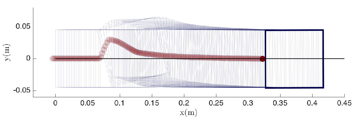

In Fig. 8, an impulsive force is applied in the direction to perturb the system about its nominal trajectory and evaluate the performance of the feedback controller. In Fig. 8(a), the simulated response of the slider to a state perturbation applied at m is compared to the experimental response of the slider in Fig. 8(b) to an external impulsive force applied using a hand held poker. Both simulated and experimental responses show that the feedback controller is successful in driving the perturbations from the nominal trajectory to zero. The initial motion of the pusher in Fig. 8(b) is trying to correct the non-zero initial conditions of the slider, which was imperfectly placed by hand. The experimental performance of the feedback controller design to a variety of external perturbations can be visualized at https://mcube.mit.edu/videos.
6.2 Trajectory Tracking
In this section, the controller design developed in Sections 5 and 6 is adapted to the problem of tracking a moving target position. The objective is to control the motion of the robotic pusher such that the sliding object reaches a target (, ). At each instant, an intermediate reference frame is defined where the unit vector points from the center of mass of the sliding object to the target position. The angle in Fig. 9 is the orientation of relative to the horizontal and the angle is the orientation of the slider relative to .


The tracking of a target position is converted into a trajectory tracking problem where the objective is to track the straight line between the current position of the slider and the target. Assuming a constant desired velocity of the sliding object, the nominal trajectory and control input , defined relative to the intermediate reference frame , are and with the desired velocity. The term denotes the prediction horizon time, which is reinitialized at each time step as . The controller design parameters used in Fig. 11 are identical to those presented in Section 8, with the exception that the max tangential velocity is set to m/s. The target tracking results are performed from zero initial conditions with the target positions given by
The simulation begins with the position tracking of Target . When the slider falls within a distance of meters of a target, the position is updated to the next target position and so on until the final position is reached. Both simulated and experimental trajectories achieve target tracking within the specified tolerance (video of experiments available at https://mcube.mit.edu/videos). The trajectories in Fig. 11 depict the robotic pusher favoring a sliding behavior when the relative angle of the sliding object is large relative to the target position. The controller elects to slide the pusher relative to the object to rotate it and then favors a sticking contact mode to push the object in a straight line towards the target position. This control strategy is intuitive and is in line with the way in which humans manipulate objects using a single finger. It is observed that the simulated trajectory results in Fig. 11(a) achieves slightly more aggressive turns than the experimental trajectory results in Fig. 11(b). Despite the unmodeled aspects of the problem, such as delay in the robot position control, quasi-static assumption, imprecise nature of friction, etc., the feedback controller makes good control decisions which drive the system in the right direction towards the desired trajectory.


7 CONCLUSION
In this work we present a feedback controller design for manipulation tasks where control acts through contact. Using a model predictive control approach combined with an integer programming formulation permits for the integration of the physical constraints associated with the dynamics of contact as well as explicitly consider the hybrid nature of the interactions. We describe two methodologies to solve the optimization program, namely Mixed-Integer Quadratic Programming and Family of Modes, which we propose to speed up the integer program for real-time control purposes. The Family of Modes method is validated through numerical simulations and experiments, where the feedback controller successfully stabilizes the motion of a sliding object through single point contact.
Following the success of the Family of Modes approach in the pusher-slider system, a natural question raised is: “How does the Family of Modes approach extend to more complex manipulation tasks?” For large set of manipulation problems involving multiple contact locations, key mode sequences can be readily identified either using physical insight of by investigating solutions to offline planning algorithms. Moreover, for many manipulation tasks, such as those involving parallel jaw grippers, there is a natural symmetry of the problem that can be leveraged to deduce important mode sequences. The application of the Family of Modes approach to multiple contact problems, such as in-hand manipulation with extrinsic dexterity [8, 9], is a direction of future work.
References
- [1] Kawasaki, H., Komatsu, T., and Uchiyama, K., “Dexterous Anthropomorphic Robot Hand With Distributed Tactile Sensor: Gifu Hand II,” IEEE/ASME Transactions on Mechatronics, Vol. 7, No. 3, 2002, pp. 296 – 303.
- [2] Mouri, T., Kawasaki, H., Yoshikawa, K., Takai, J., and Ito, S., “Anthropomorphic Robot Hand: Gifu Hand III,” International Conference on Control, Automation and Systems, Jeonbuk, Korea, October 16 – 19, 2002, pp. 1288 – 1293.
- [3] Gaiser, I., Schulz, S., Kargov, A., Klosek, H., Bierbaum, A., Pylatiuk, C., Oberle, R., Werner, T., Asfour, T., Bretthauer, G., and and, R. D., “A New Anthropomorphic Robotic Hand,” IEEE-RAS International Conference on Humanoid Robots, Daejon, Korea, December 1 – 03, 2008, pp. 418 – 422.
- [4] Yousef, H., Boukallel, M., and Althoefer, K., “Tactile Sensing for Dexterous In-Hand Manipulation in Robotics–A Review,” Sensors and Actuators A: Physical, Vol. 167, No. 2, 2011, pp. 171 – 187.
- [5] Li, R., Jr., R. P., Yuan, W., Andreas ten Pas, N. R., Srinivasan, M. A., and Adelson, E., “Localization and Manipulation of Small Parts Using GelSight Tactile Sensing,” IEEE/RSJ International Conference on Intelligent Robots and Systems, Chicago, Illinois, September 14 – 18, 2014, pp. 3988 – 3993.
- [6] Bicchi, A. and Kumar, V., “Robotic Grasping and Contact: A Review,” IEEE International Conference on Robotics and Automation, San Francisco, California, April 24 – 28, 2000, pp. 348 – 353.
- [7] Salisbury, J. K. and Craig, J. J., “Articulated Hands: Force Control and Kinematic Issues,” The International Journal of Robotics Research, Vol. 1, No. 1, 1982, pp. 4 – 17.
- [8] Chavan-Dafle, N., Rodriguez, A., Robert Paolini, B. T., Srinivasa, S., Erdmann, M., Mason, M. T., Lundberg, I., Staab, H., and Fuhlbrigge, T., “Extrinsic Dexterity: In-Hand Manipulation with External Forces,” IEEE International Conference on Robotics and Automation, Hong Kong, China, May 31 – June 5, 2014, pp. 1578 – 1585.
- [9] Chavan-Dafle, N. and Rodriguez, A., “Prehensile Pushing: In-Hand Manipulation with Push Primitives,” IEEE/RSJ International Conference on Intelligent Robots and Systems, Hamburg, Germany, September 28 – October 02, 2015.
- [10] Posa, M., Cantu, C., and Tedrake, R., “A Direct Method for Trajectory Optimization of Rigid Bodies Through Contact,” The International Journal of Robotics Research, Vol. 33, No. 1, 2014, pp. 69 – 81.
- [11] Tassa, Y. and Todorov, E., “Stochastic Complementarity for Local Control of Discontinuous Dynamics,” Proceedings of Robotics: Science and Systems, Zaragoza, Spain, June 27 – 30, 2010.
- [12] Tassa, Y. and Todorov, E., “Synthesis and Stabilization of Complex Behaviors through Online Trajectory Optimization,” IEEE/RSJ International Conference on Intelligent Robots and Systems, Vilamoura, Portugal, October 7 – 12, 2012.
- [13] Stewart, D. E. and Anitescu, M., “Optimal Control of Systems with Discontinuous Differential Equations,” Numerische Mathematik, Vol. 114, No. 4, 2009, pp. 653 – 695.
- [14] Mason, M. T., “Mechanics and Planning of Manipulator Pushing Operations,” The International Journal of Robotics Research, Vol. 5, No. 3, 1996, pp. 53 – 71.
- [15] Lynch, K. M. and Mason, M. T., “Stable Pushing: Mechanics, Controllability, and Planning,” The International Journal of Robotics Research, Vol. 15, No. 6, 1996, pp. 533 – 556.
- [16] Lynch, K., Maekawa, H., and Tanie, K., “Manipulation and Active Sensing by Pushing Using Tactile Feedback,” IEEE/RSJ International Conference on Intelligent Robots and Systems, Raleigh, USA, July 7 – 10, 1992, pp. 416–421.
- [17] Poulakakis, I. and Grizzle, J. W., “The Spring Loaded Inverted Pendulum as the Hybrid Zero Dynamics of an Asymmetric Hopper,” IEEE Transactions on Automatic Control, Vol. 54, No. 8, 2009, pp. 1779 – 1793.
- [18] Decker, L., Berge, C., Renous, S., and Penin, X., “An Alternative Approach to Normalization and Evaluation for Gait Patterns: Procrustes Analysis Applied to the Cyclograms of Sprinters and middle-Distance runners,” Journal of Biomechanics, Vol. 40, No. 9, 2007, pp. 2078 – 2087.
- [19] S. Goyal, A. R. and Papadopoulos, J., “Wear,” Planar Sliding with Dry Friction Part 1. Limit Surface and Moment Function, Vol. 143, 1991, pp. 307 – 330.
- [20] Lee, S. H. and Cutkosky, M., “Journal of Manufacturing Science and Engineering,” Fixture Planning with Friction, Vol. 113, No. 3, 1991, pp. 320 – 327.
- [21] Gurobi Optimization, I., “Gurobi Optimizer Reference Manual,” 2015.
- [22] Nemhauser, G. L. and Wolsey, L. A., Integer Programming and Combinatorial Optimization, Wiley, Chichester, England, 1988.