Authors’ address: Department of Electrical Engineering, Indian Institute of Technology Bombay, Mumbai, India 400076;
email: {vineet, jayakrishnan.nair, sc}@ee.iitb.ac.in
Congestion Control for Network-Aware Telehaptic Communication
Abstract
Telehaptic applications involve delay-sensitive multimedia communication between remote locations with distinct Quality of Service (QoS) requirements for different media components. These QoS constraints pose a variety of challenges, especially when the communication occurs over a shared network, with unknown and time-varying cross-traffic. In this work, we propose a transport layer congestion control protocol for telehaptic applications operating over shared networks, termed as dynamic packetization module (DPM). DPM is a lossless, network-aware protocol which tunes the telehaptic packetization rate based on the level of congestion in the network. To monitor the network congestion, we devise a novel network feedback module, which communicates the end-to-end delays encountered by the telehaptic packets to the respective transmitters with negligible overhead. Via extensive simulations, we show that DPM meets the QoS requirements of telehaptic applications over a wide range of network cross-traffic conditions. We also report qualitative results of a real-time telepottery experiment with several human subjects, which reveal that DPM preserves the quality of telehaptic activity even under heavily congested network scenarios. Finally, we compare the performance of DPM with several previously proposed telehaptic communication protocols and demonstrate that DPM outperforms these protocols.
1 Introduction
Telehaptic applications, such as telesurgery [3], involve long distance transfer of haptic-audio-visual information between distantly located users. The performance of a telehaptic activity is governed by a set of Quality of Service (QoS) parameters, specific to each type of media. According to [29, 27, 38], the QoS one-way delay and jitter specifications for multimedia are, respectively, as follows: interactive video - 400 ms and 30 ms, audio - 150 ms and 30 ms, haptic - 30 ms and 10 ms. Non-conformance to the above constraints leads to degraded human perception, and can potentially compromise the quality of the telehaptic activity [23]. In particular, a haptic QoS violation results in destabilizing the haptic global control loop [11, 3], and a deteriorated perception of haptic objects. Hence, multimedia data reception and display within the prescribed QoS deadlines plays a pivotal role in determining the stability and the overall performance of a telehaptic task.
In a shared network, like the Internet, a telehaptic source shares the network resources with other concurrent traffic streams. As a result, the intensity of the cross-traffic encountered by a telehaptic stream on a shared network is both unknown as well as time-varying. In such a scenario, the transmission of telehaptic data in a network-oblivious manner can be highly sub-optimal. In particular, at times when the network is severely congested, a network-oblivious telehaptic stream may suffer large delays and frequent packet losses, leading to QoS violations. Note that this is all the more likely in resource constrained networks, such as wireless ad-hoc networks. On the other hand, at times when the network is lightly loaded, it may be feasible to transmit telehaptic data at its peak rate. The above discussion motivates the need for a network-aware telehaptic transmission scheme. In this paper, we propose such a scheme, which monitors network conditions in real-time and adapts the telehaptic data rate accordingly to achieve congestion control in a lossless manner.
1.1 Contributions of the Article
In this article, we focus on point-to-point telehaptic communication over a shared network. Specifically, we propose a network-aware protocol for multiplexing and transmission of haptic/audio/video data between two telehaptic nodes connected via a shared network. The protocol monitors network congestion in real time and (losslessly) adapts the transmission rate on the forward and the backward channels to maintain QoS compliance.
The proposed protocol receives haptic/audio/video frames from the respective capture devices at each node and delivers these frames to the corresponding display devices at the other end. By design, our protocol is robust to the type and resolution of the media devices, as well as the audio/video encoding standard employed. Thus, our protocol may be viewed as a transport layer congestion control solution for point-to-point telehaptic communication, akin to the Transmission Control Protocol (TCP) for elastic internet traffic.
The proposed protocol has two main components:
- 1.
Network feedback module: The network feedback module (see Section 2.3) is a novel mechanism for real time monitoring of end-to-end delays on the network. It exploits the bidirectional nature of telehaptic traffic to convey delays on each channel to the corresponding transmitter. Specifically, the end-to-end delays as measured by a receiving node are piggybacked on telehaptic data packets on the reverse channel (see Figure 3). This provides real-time feedback of network state to the transmitting node with negligible overhead (3 bytes per packet). The proposed network feedback module can also potentially be utilized for other (bidirectional) media streaming applications like video conferencing.
- 2.
Dynamic packetization module: The dynamic packetization module (DPM) (see Section 2.4) is a lossless mechanism for telehaptic data rate adaptation, based on the delay feedback from the network feedback module. DPM is motivated by the following observation: Under telehaptic data transmission at the default packetization rate of 1000 packets/sec, the overhead due to packet headers from various layers accounts for almost half the total telehaptic traffic. Thus, when the network is congested, DPM dynamically merges successive telehaptic fragments into a single packet, thereby lowering the overall transmission rate to match the available network capacity. Naturally, this transmission rate reduction is achieved at the expense of additional packetization delay at the transmitter.
We evaluate the proposed telehaptic transmission scheme via extensive simulations as well as human subjective tests through a real-time telepottery experiment (see Section 4). Our simulations reveal that DPM meets the telehaptic QoS specifications even under extremely congested network settings. Our subjective tests confirm that DPM provides a seamless telehaptic user experience in a congested network. We also compare DPM with other recently proposed telehaptic communication protocols, and demonstrate that DPM outperforms these protocols with respect to QoS compliance.
Finally, to evaluate the performance of the proposed scheme analytically, we derive bounds for the maximum haptic/audio/video delay on a network with a single bottleneck link, assuming constant bit-rate (CBR) cross-traffic (see Appendix B and C). These delay characterizations are useful in identifying network settings where QoS-compliant telehaptic communication is feasible.
1.2 Related Work
There have been several attempts to address the problem of large telehaptic bandwidth requirement. The standard input and output update rate of the haptic signal is 1 kHz. In order to reduce the packetization delay encountered by the haptic samples, the conventional approach follows fixed haptic packetization at 1 kHz (1 packet per sample) for transmission over the network. This approach is highly bandwidth demanding, and is not friendly to other network users. To counter this issue, the works in [20, 8, 19, 18, 9, 34] explored adaptive sampling which exploits the perceptual limitation of the human haptic system to achieve lossy haptic signal compression. A just noticeable difference (JND) metric adaptively marks the haptic samples that are not perceivable by the human users. The communication system refrains from transmitting such samples, thereby reducing the telehaptic data rate. The missing haptic samples are then reconstructed at the receiver using standard extrapolation techniques listed in [15]. However, critical operations, like telesurgery, necessitate accurate replication of the surgeon’s hand movements. In such scenarios, a minor loss of precision due to adaptive sampling could result in potentially irreparable damage. Also, a teleoperator, such as a robotic device, could practically sense all haptic samples; in such cases, adaptive sampling discards perceptually significant samples. Another networking-related issue with adaptive sampling is the following. The instantaneous source rate of adaptive sampling depends purely on the speed of haptic interaction, and can at times far exceed the average source rate. As a result, provisioning the network for the average source rate can lead to serious QoS violations; this is demonstrated in Section 4.3. In other words, adaptive sampling does not provide any real economies with respect to network bandwidth requirement – one needs to provision network capacity for the peak telehaptic data rate in order to avoid QoS violations.
Several application layer protocols have been specifically designed for telehaptic communication. ALPHAN: Application Layer Protocol for HAptic Networking, proposed in [2], implements haptic and graphic data communication at the packetization rate of 1 kHz. AdMux: Adaptive Multiplexer [10] proposes a statistical multiplexing scheme for scheduling haptic-audio-video packet transmission based on the QoS requirements and changing network behavior. Haptics over Internet Protocol (HoIP) for point-to-point communication, proposed in [14], addresses media multiplexing and telehaptic communication involving haptics, audio and video data. The above mentioned protocols carry out telehaptic transmission at the peak rate, and hence do not address the problem of congestion control. In [7], the authors consider visual-haptic multiplexing over constant-bitrate (CBR) communication links, employing adaptive sampling for haptic signal compression. However, the drawbacks of adaptive sampling mentioned previously apply here; see Section 4.3 for a demonstration.
The work in [12] explores the possibility of merging multiple haptic samples in a packet to reduce the telehaptic data rate. In contrast with the scheme proposed in this paper, the scheme in [12] always combines a fixed number of haptic samples, irrespective of the network conditions. Note that this implies unnecessary packetization delay even when the network is uncongested. Moreover, the authors showed in a particular setting that a packetization interval of 8 ms results in a satisfactory user performance. On the contrary, we demonstrate (see Figure 5) that the packetization intervals greater than 4 ms result primarily in increasing end-to-end delays, without any substantial reduction in the telehaptic data rate.
Note that the above mentioned proposals are all network-oblivious, i.e., they do not adapt the telehaptic transmission rate based on network conditions. The literature provides a few works that have considered network-aware telehaptic rate adaptation. We discuss these next.
In [26], the authors propose a network adaptation scheme for merging haptic samples based on packet losses arising out of congestion. Such a scheme is reactive to network congestion, in the sense that data rate reduction is activated only after detecting persistent packet losses. Clearly, such a loss-based congestion control mechanism is not suitable for highly delay-sensitive telehaptic applications. We note that [26] does not provide much detail about the rate adaptation mechanism itself; also, the effects of this rate adaptation on other concurrent network flows are not analyzed.
The authors in [40] propose the first delay-sensitive haptic communication protocol named Efficient Transport Protocol (ETP). ETP detects congestion based on round-trip-time (RTT) measurements. Once congestion is detected, ETP reduces the telehaptic data rate by increasing the interpacket gap, i.e., by downsampling the haptic signal. In contrast, the protocol proposed in this paper preserves the fidelity of the haptic signal, adapting instead the packetization rate based on the congestion level in the network.
The paper most closely related to ours is [24], which proposes NAFCAH: Network Adaptive Flow Control Algorithm for Haptic data. Like DPM, NAFCAH adapts the number of haptic samples to be merged into a packet on the forward channel based on network conditions. However, there are two crucial differences between NAFCAH and DPM. First, when congestion is detected, NAFCAH decreases its transmission rate in stages. In contrast, DPM responds to congestion with an aggressive rate reduction, which enables network buffers to get flushed quickly, minimizing the possibility of QoS violations. Second, NAFCAH monitors congestion based on RTT measurements. However, under asymmetric network conditions, RTT may not provide an accurate estimate of the (one-way) delay on the forward channel. In contrast, DPM estimates the delay on the forward and backward channels separately. The performance implications of the above differences are demonstrated in Section 4.3.
The authors of [16] propose a network-aware opportunistic adaptive haptic sampling mechanism, wherein the adaptive sampling threshold is varied based on the congestion level in the network. Note that the limitations of adaptive sampling discussed earlier apply to this work as well.
Finally, we contrast our work with the Real-time transport protocol (RTP) [35], which is the most commonly used protocol for audio/video streaming and has also been recommended by some researchers for telehaptic communication; see for example [36]. RTP uses report-based notification for monitoring the network conditions at regular intervals of time. The multimedia receiving agent sends RTP Control Protocol (RTCP) receiver reports to the transmitters, for QoS monitoring, once in every 500 ms [39]. However, as we demonstrate in Section 4.3, such sparse feedback is insufficient for telehaptic applications, which are sensitive to network changes that occur over a timescale of tens of milliseconds.
1.3 Organization of the Article
The article is organized as follows. In Section 2, we describe the configuration of a typical telehaptic environment, and explain in detail the design and working of the proposed telehaptic communication framework. In Section 3, we discuss the setup for simulations and the real-time telepottery experiment. Section 4 presents the findings of the experiments, and in Section 5, we state our conclusions. Finally, in the appendix, we describe the DPM header structure, and characterize the maximum end-to-end haptic/audio/video delay under the proposed scheme in a simple (single bottleneck) network setting.
2 Design of Telehaptic Communication Framework
In this section, we explain the standard telehaptic setting on a shared network, and describe the techniques proposed in this article for a lossless, network-aware, adaptive telehaptic data communication.
2.1 Typical Telehaptic Environment

We consider a typical point-to-point telehaptic application, like telesurgery, running on a shared network as shown in Figure 1. The operator (OP) acts as the master and sends the current position and velocity commands to the teleoperator (TOP). In response, the TOP, acting as the slave, transmits force information to the OP, in addition to auditory and visual data. The channels on which the operator and teleoperator transmit telehaptic data are called forward and backward channels, respectively. Note that the telehaptic traffic is bidirectional and asymmetric in nature. Moreover, the forward and backward channel are also asymmetric; in general, they may differ with respect to routing paths, capacity, as well as cross-traffic. Our network feedback module, described in Section 2.3, estimates congestion on the forward and the backward channels separately. Finally, we remark that the particular master-slave setup depicted in Figure 1 is assumed only for concreteness in exposition. Our proposed telehaptic communication protocol works in any general point-to-point telehaptic application.
2.2 Media Multiplexing Framework
In this section, we describe our media multiplexing framework. Multiplexing the media frames appropriately from the different capturing devices and forwarding them to the transmitter is a critical task in any network based real-time interactive application, since it directly influences the QoS adherence of the respective media. The authors in [7] rightly explain the importance of splitting a large video frame into smaller parts for transmission. Naturally, if a large video frame is transmitted in a single packet, it would clog the network for a long time, thereby delaying the subsequent haptic/audio samples substantially. The media multiplexing framework proposed here is an adaptation of that in [7, 14].
Our media multiplexer works in synchronization with the sampling of the haptic signal, which we assume occurs at the default rate of 1 kHz. Each time a haptic sample is generated, our multiplexer generates a telehaptic fragment of size which contains the latest haptic sample, as well as audio/video data as explained below.11 1 If there is no audio/video data, as is the case in the communication from the OP to the TOP (see Fig. 1), then each telehaptic fragment is composed of a single haptic sample.
Let and denote the peak frame generation rate (in frames per second) for audio and video, respectively. Let and denote the maximum size (in bytes) of an audio and video frame, respectively.22 2 and depend on the audio/video encoding standards employed. It is important to note that the proposed protocol, which operates at the transport layer, is robust to the encoding standards used. The (peak) telehaptic payload generation rate, denoted by (in kbps), is expressed in terms of the individual media parameters as
| (1) |
Here, denotes the haptic sampling rate (assumed to be 1 kHz), and denotes the size of a haptic sample.33 3 Throughout this article, we use the terms sample and frame interchangeably.
In order to maintain equilibrium between the payload generation and the multiplexing, the size (in bytes) of the telehaptic fragment multiplexed per milli-second is given by
| (2) |
Due to the mandatory haptic sample in each telehaptic fragment, the size of audio/video data in a fragment is given by
| (3) |
Since audio has a stricter QoS constraint than video, our multiplexer gives audio data priority over video data. That is, in each telehaptic fragment, the multiplexer packs bytes of audio/video data (not previously multiplexed), giving strict priority to audio over video. It can be shown that the proposed hierarchical priority-based multiplexing mechanism leads to substantially lower audio/video jitter compared to the first-come-first-served multiplexing mechanism proposed in [14].
2.3 Network Feedback Module
The network feedback module performs two functions: i) it monitors the delays on the forward and backward channels separately through in-header delay notification mechanism, and ii) based on the received piggybacked delays it generates triggers for the respective transmitters to adapt their data rates. We explain these functions in the following.
2.3.1 In-header delay notification

We exploit the bidirectional nature of the telehaptic traffic to convey end-to-end delays on each channel to the respective transmitter without transmitting specialized reports (unlike RTP). The in-header delay notification mechanism inserts the end-to-end delay encountered by the latest received packet into the header of the packet to be transmitted, as shown in Figure 3. In particular, the headers of packets transmitted on the forward channel include the end-to-end delay experienced by the last received packet on the backward channel, and vice-versa. This mechanism enables real-time monitoring of the state of congestion on each channel separately, with a negligible overhead of 3 bytes per packet.
The telehaptic nodes are time-synchronized using Network Time Protocol (NTP) [28]. The end-to-end delay encountered by a telehaptic packet received is thus calculated as the difference between the time of reception and the timestamp of the earliest haptic sample embedded in the received packet. Note that merging of multiple telehaptic fragments in a packet is explained in detail in Section 2.4.
The in-header delay notification mechanism is more effective than the report-based notification of RTP for three major reasons. Firstly, the higher rate of delay notifications provides finer details of network changes. This enables the telehaptic nodes to swiftly adapt the telehaptic rate to the changing network conditions. Secondly, our scheme does not transmit specialized packets to convey delay feedback, and thus induces a smaller overhead compared to RTP. Thirdly, the in-header delay notification mechanism estimates the delays on the forward and backward channels separately, enabling each transmitter to adapt its rate based on the state of the corresponding channel.
2.3.2 Generation of rate-adaptation triggers
Based on the trend observed in the measured delays on each channel, the network feedback module generates two triggers for the corresponding transmitter. The trigger signals that the channel is getting congested; this causes the DPM module to reduce the telehaptic data rate if possible (see Section 2.4). The trigger signals that the channel delays are steady; this causes the DPM module to probe if the channel has spare capacity by increasing the telehaptic data rate if possible (see Section 2.4).
In order to trace the delay pattern, we use an exponentially weighted moving average filter defined by
| (4) |
where Here, denotes the th end-to-end delay measurement.44 4 Note that the OP (TOP) may receive the same delay measurement multiple times; this can happen if the TOP (OP) makes multiple packet transmissions between successive receptions. To avoid the same delay measurement from resulting in multiple updates in Equation (4), we include a one-bit field named delay indicator (field D of Table 3 in Appendix A) to the packet header. This field is set to 1 in case of a repetitive transmission of a previously computed delay, and 0 in case of the transmission of a newly computed delay.
The network feedback module generates triggers as follows. The trigger is generated on observing continuous increasing measurements in Note that a steady increase in the end-to-end delays indicates that queues in the network are building up due to congestion. The trigger is generated if the most recent entries in satisfy two conditions: (i) the entries exhibit neither an increasing nor a decreasing trend, and (ii) the latter entries are within a tolerance interval of 10% around the first. Note that generation of the trigger signals that network conditions are steady. It is worth mentioning that since the generation of triggers is based on a trend of the end-to-end delays, the proposed rate adaptation scheme remains robust to time synchronization errors of NTP. In our experiments, reported in Section 4, we set 0.2, as recommended in [30], and 8.
2.4 Dynamic Packetization Module
In this section, we describe the dynamic packetization module (DPM), which adapts the telehaptic data rate based on the triggers generated by the network feedback module. We begin by presenting some calculations that illustrate the extent of telehaptic data rate variation possible by varying the packetization rate.
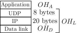
Assuming Ethernet on the data link layer, the overall overhead per packet due to the link layer ( 26 bytes), IP, and UDP headers equals 54 bytes (see Figure 3). Adding to this our protocol’s overhead () of 13 bytes (see Appendix A), we arrive at a net overhead of 67 bytes/packet. If we transmit each telehaptic fragment as a separate packet (this corresponds to a 1 kHz packetization rate), this amounts to an overall overhead rate of 536 kbps. For a standard TOP payload rate of 560 kbps (haptic - 96 kbps, audio - 64 kbps, video - 400 kbps), the overhead constitutes a substantial proportion (48.9%) of the telehaptic traffic.55 5 The overhead represents an even higher proportion (72.09%) of the telehaptic traffic from the OP to the TOP, since the payload is composed of only haptic data.
Now, suppose that we merge consecutive telehaptic fragments into a single packet for transmission. We refer to this scheme as the -merge packetization scheme, and we refer to the special case as the no-merge packetization scheme. The telehaptic data rate corresponding to the -merge packetization scheme (in kbps) is given by
| (5) |
where is the telehaptic payload generation rate given by (1) and denotes the overhead rate under the no-merge scheme. Taking 536 kbps, Figure 5 presents the variation of telehaptic overhead rates and packetization delay for different -merge schemes. Note that these packetization delays correspond to the earliest haptic sample in the packet. Assuming 560 kbps, we see that on the backward channel the telehaptic transmission rate for the no-merge scheme equals 1096 kbps, whereas the transmission rate for the 4-merge scheme equals 694 kbps. We observe that there is a substantial scope for losslessly varying the telehaptic transmission rate by controlling the packetization parameter Of course, the data rate reduction from increasing comes at the cost of a higher packetization delay at the source.
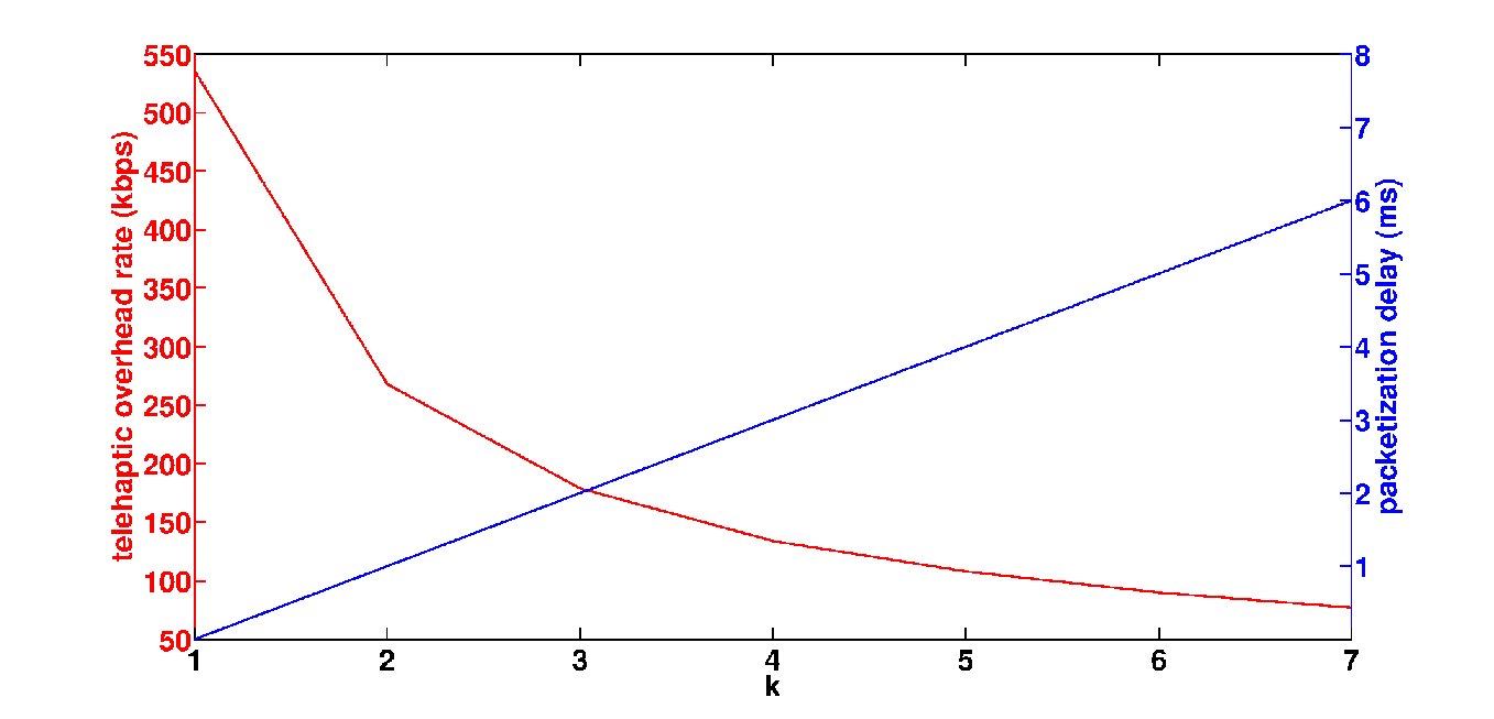

The idea behind DPM is to dynamically adapt the packetization parameter depending on network conditions. In other words, DPM dynamically switches between different -merge schemes based on the triggers from the network feedback module. From Figure 5, we note that the overhead reduction becomes insignificant for large values of whereas the packetization delay grows linearly in Thus, DPM confines the adaptation of to the range In this work, we set
DPM is a step-increase-multistep-decrease (SIMD) algorithm. This is a variation of the classical additive-increase-multiplicative-decrease (AIMD) congestion control mechanism of TCP [6]. Specifically, on receiving the trigger (recall that this trigger signals that the network is getting congested), DPM sets Thus, on sensing congestion in the network, DPM decreases the telehaptic data rate aggressively in order to decongest the network in the shortest possible time. On the other hand, on receiving the trigger (recall that this trigger signals that network delays are steady), DPM decreases by 1 if 1. Thus, on sensing that the network is in a steady state, DPM probes if a higher data rate is achievable by decreasing by one unit. Figure 5 shows a finite state transition diagram representation of DPM.

Note that DPM’s dynamic packet rate adaptation will induce additional
jitter in the receiver. To get sense of the jitter caused by DPM, we
perform the following simple analysis, focusing only on haptic jitter
(note that the haptic stream has the tightest jitter constraint). It
is easy to see that the maximum jitter occurs when switching from
to Consider the sequence of haptic samples
shown in Figure 6. Suppose that initially,
Note that sample number is generated at time and
is received and displayed at time . Here,
denotes the one-way propagation delay, and and denote the queueing delay and transmission delay
of the packet containing sample number , respectively. Now, suppose that
starting from sample number we switch from to In
this case, sample which is generated at time will only
get transmitted at time (along with the next three samples), and
will get received and displayed at time Here,
and denote the queueing and transmission delays,
respectively, experienced by the packet containing sample Thus,
the jitter of the haptic sample equals the difference between
its actual display time and its expected display time:
Note that Assuming then that and
are comparable, we can bound the jitter by
Thus, we see that by restricting to be at most 4 under DPM, we
introduce an additional jitter of at most on the haptic
stream. Note that the subsequent 4-merge packet (carrying haptic samples []) arrives at . We validate the correctness
of the jitter analysis through simulation results reported in Table 1.

Overview of Protocol Architecture: Figure
7 presents an overview of the proposed telehaptic
communication framework. We explain the working with respect to the
TOP, whereas similar operations are carried out at the OP as well. On
receiving the telehaptic packet at the TOP, the depacketizer
module decodes the header information. Based on the header contents,
the payload is forwarded to the appropriate media display devices. The
backward channel delay () in the header is supplied to the
network feedback module for learning the recent changes in
the backward channel. Based on the delay analysis, the network
feedback module generates triggers () appropriately. On
arrival of a trigger, the DPM selects , which is communicated to
the packetizer for composing the telehaptic packets. The TOP
also calculates the end-to-end delay on the forward channel
() after every packet reception, which is sent to the
packetizer for inclusion in the packet header that is transmitted to the OP.
3 Experimental Design
In this section, we describe the setup used in our experiments to assess the performance of the telehaptic data transmission scheme proposed in this paper. The objective of the experiments is to investigate the ability of DPM to perform congestion control under heavy cross-traffic scenarios. The performance metrics we consider are QoS adherence, signal-to-noise ratio (SNR) of the reconstructed haptic signal at the receiver, and the perceptual quality of the displayed haptic-audio-video signal. We first describe the setup used in our simulations, and then describe the setup of the real-time telepottery experiment. The results of these experiments follow in Section 4.
3.1 Simulation Setup

Our simulations are carried out using NS-3, a discrete event network simulator [31]. We consider a network with a single bottleneck dumbbell topology connecting the OP and the TOP, as shown in Figure 8. In order to simulate asymmetric network conditions on the forward and the backward channels, we create unidirectional links between the OP and the TOP node. All links have identical capacities (denoted by ) of 1.5 Mbps.66 6 1.5 Mbps has been picked to represent the typical capacity of a medium speed internet link. However, the nature of our findings remain robust to the channel capacity. To simulate cross-traffic on the forward (respectively, backward) channel, we add source-destination pairs (respectively, ) as indicated in Figure 8. Note that and act as the bottleneck links for the telehaptic traffic on the forward and backward channels, respectively. Thus, queueing delay experienced by the telehaptic application due to network cross-traffic is observable only at the intermediate nodes and .
The haptic payload rates on the forward and backward channels are set to 192 kbps and 96 kbps [14], respectively. The TOP generates audio frames of size 160 bytes 20 ms apart, and video frames of size 2 kB, 40 ms apart. This corresponds to payload rates on the backward channel of 64 kbps and 400 kbps respectively for audio and video. Considering the application layer header sizes (see Appendix A), the no-merge data rate on the forward and backward channels are calculated to be 688 kbps and 1096 kbps, respectively.
Finally, the propagation delay of each link is set to 5 ms. Hence, the one-way propagation delay (denoted by ) is 15 ms, which is typically the propagation delay exhibited by a transcontinental link of around 2000 miles. All nodes follow first-in-first-out (FIFO) and droptail queueing of packets.
3.2 Perceptual Experiment Setup


It is important to investigate the qualitative effect of DPM on human multimedia perception, which is not possible through simulations. For this purpose, we conduct a real-time telepottery experiment in which a human subject interacts with a remote, virtual pottery model on a real network through haptic, audio and visual feedback, as described in [14]. Figure 9 demonstrates the setup of the telepottery experiment showing the human subject remotely exploring the virtual clay model. The volume preserving pottery model [5] is rendered at the TOP, which is equipped with a haptic device and a generic webcam. The interaction with the remote scene happens through audio-visual feedback and a separate haptic device for the haptic feedback. The master-slave relationship between the two haptic devices is implemented using a proportional-derivative controller; see [14] for more details.
The subjects were initially briefed about the concept of force feedback as few of them were new to the notion of haptics. Later, we explained them the telepottery task in detail accompanied by a live demonstration of the task. The telepottery task involves the subject exploring and manipulating a rotating virtual clay model. The task is to design a clay pot. There is no benchmarking so far as the shape of the pots is concerned, since the idea behind the experiment is to assess human perception and not skill. The subject pushes the haptic device stylus so as to establish contact with the clay model and shape it into a pot. The training phase involved the participants performing the task to get acquainted with the telepottery setup. During this phase, the participants explored the telepottery model under an expert’s guidance until they were confident of performing the task independently. In order to avoid any perceptual degradation due to the network, the training was performed on a very high bandwidth network, under the no-merge packetization scheme.
After the training, the subjects were moved to a test setup
consisting of a network emulator tool that allows for configuring the
network capacity and propagation delay. Under the emulated network
conditions, the subjects independently perform the telepottery task
twice: once with no-merge scheme, and once with the proposed DPM
scheme. Finally, the subjects were asked to grade the experience of
each of the two test experiments, relative to the training, based on
three perceptual parameters: transparency (the subjects felt
as if they were present in the remote virtual environment and are
directly interacting with the objects)
[25], smoothness (how smooth or
jerky is the feedback) [22] and
overall experience. The grading of each of the three
parameters was based on degradation category rating (DCR)
[21, 37, 13] that
assigns
a subjective scale to a text descriptor in the following manner:
5- imperceptible; 4- slight disturbance, but not annoying;
3- slightly annoying; 2- annoying; 1- very annoying.
For example, the subjects chose 5 if they felt that the degradation in
perceptual quality of the test experiments was imperceptible compared
to the training phase.
The average training duration was measured to be around 12 minutes, and the average duration for each of the test experiments was around 6 minutes. The subjects had no prior knowledge about the protocol being tested, thereby avoiding grading bias.
3.2.1 System Settings
In the real-time telepottery experiment, we use two Phantom Omni haptic devices which capture the low-level dimensions of human haptic perceptual system [4]. Two desktop computers, each with 4 GB RAM and running Windows 7 operating system are employed. The audio-visual information is captured at the TOP using a Microsoft Lifecam VX-2000 webcam. The TOP transmits uncompressed audio and video frames at the rate of 164 kbps and 1.1 Mbps, respectively. For these experiments, we increase the channel capacity by 800 kbps compared to the simulation setup to account for the additional audio/video payload.
The network is emulated using a standard network emulator tool called Dummynet [33]. The training phase of the telepottery experiment is performed on a 100 Mbps network. For the testing phase, the emulated channel capacity and one-way propagation delay are configured to 2.3 Mbps and 15 ms, respectively, for both the forward and the backward channel. In the testing phase, we introduce constant bit-rate (CBR) cross-traffic stream of intensity 400 kbps on the backward channel. In addition, we introduce variable bit-rate (VBR) source with intensity [320, 480] kbps with a mean of 400 kbps on the backward channel.
3.2.2 Human Subjects
The call for participation in the telepottery task was published on noticeboards in the university. All human subjects who took part in the experiment were either students or faculty members at the university. A total of twenty subjects (ten female and ten male, eighteen right-handed and two left-handed) participated in the perceptual task. The subjects belonged to the age group of twenty three to fifty two years, and none of them suffered from any known neurophysiological disorders. Out of the twenty participants, fourteen were novice haptic users and the rest were regular users of haptic devices. However, all subjects underwent extensive training prior to the test experiments.
4 Experimental Results
In this section, we present a comprehensive experimental evaluation of DPM. Simulation results are presented in Section 4.1, and the results of our perceptual experiments are presented in Section 4.2. In Section 4.3, we compare the performance of DPM with the state of the art in telehaptic communication protocols.
4.1 Simulation Results
In this section, we present the performance evaluation of DPM via simulations. Specifically, we analyze the interplay between DPM and network-oblivious cross-traffic, highlighting DPM’s response to highly congested network conditions. For brevity, we present results corresponding to only the backward channel; the performance of DPM on the forward channel is similar.
The simulation begins at time at which point the telehaptic stream commences transmission. Starting at we also maintain VBR stream on backward channel with intensity [320, 480] kbps with a mean of 400 kbps.77 7 A Skype video-conferencing connection consumes approximately 400 kbps of bandwidth in each direction. Thus, the VBR cross-traffic can be thought of as a video-conferencing stream contending with the telehaptic stream on the bottleneck link. At ms, we additionally introduce CBR cross-traffic stream on the backward channel. The intensity of the CBR source is used as a control parameter to tune the level of congestion on the backward channel. Note that the peak telehaptic data rate on the backward channel equals 1096 kbps (under no-merge packetization), whereas the minimum data rate equals 694 kbps (with under DPM). Thus, denoting the intensity of the CBR stream on the backward channel by we note that when kbps, the telehaptic stream has insufficient bandwidth to transmit at its peak rate. (Recall that 1.5 Mbps.) Moreover, kbps implies that the network is overloaded, since the available capacity is insufficient to even sustain the minimum telehaptic data rate. Thus, the effectiveness of DPM is to be gauged over the range of kbps. In most of our experiments, we set kbps, which represents a highly congested backward channel. The cross-traffic rates on the forward channel are identical to that on the backward channel. The simulations run for 500 seconds. The throughput, average jitter and packet loss measurements presented in this section are computed after the CBR cross-traffic is switched on, i.e., over the interval [0.5, 500] seconds.
It is important to note that since the proposed protocol
operates at the transport layer (TL), all delays reported in this
section are TL-TL measurements. In other words, we report the
latency between the arrival of a haptic/audio/video sample at the TL
of the sender and the reception of the same sample at the TL of the
receiver. The delays experienced by the OP/TOP in practice (the
so-called ‘glass-to-glass’ delays) would include the additional lag
introduced by the media devices as well as the encoding/decoding
latency.


Temporal variation of telehaptic delay: We begin by demonstrating the temporal evolution of the delay experienced by the telehaptic stream under DPM. Figure 10 shows the delay experienced by the haptic samples as a function of the sample generation time, corresponding to = 260 kbps and 400 kbps.
Let us first consider Figure 10(a). For = 260 kbps, the capacity available to the telehaptic stream on the backward channel equals 840 kbps, which is less than the no-merge transmission rate of 1096 kbps, but more than the 2-merge transmission rate of 828 kbps. Once the CBR source turns on at 500 ms, the telehaptic stream, initially operating at sees a rapid delay build-up. DPM responds to this build-up by switching to This aggressive rate reduction allows the network buffers to drain quickly, avoiding a QoS violation. Once DPM sees a steady delay zone, it probes for a higher telehaptic data rate by decreasing by 1. But when DPM makes the switch from to the overall network load once again exceeds the capacity of the bottleneck link. This in turn leads to a delay build-up, and the cycle repeats.
Figure 10(b) has a similar interpretation. For = 400 kbps, the capacity available to the telehaptic stream on the bottleneck link equals 700 kbps, which is less than the 3-merge transmission rate of 739 kbps, but more than the 4-merge transmission rate of 694 kbps. In this case, the switch from to causes a delay build-up, forcing DPM to revert to
In conclusion, we see that DPM adapts its transmission rate depending on the intensity of cross-traffic it experiences. Moreover, against a steady cross-traffic, DPM results a roughly periodic delay evolution. This is typical of congestion control algorithms; see, for example, [17]. Note that even when the backward channel is highly congested (see Figure 10(b)), DPM manages to keep the telehaptic delays below the prescribed QoS limits.88 8 It is worth remarking that the haptic delay is dependent on the overall cross traffic intensity, the link capacities, as well as propagation delays. For haptic QoS compliance, we need to ensure that the maximum haptic delay does not exceed 30 ms. We perform a mathematical analysis for characterizing the maximum haptic delay in Appendix B. This enables us to identify the network settings under which haptic QoS adherence is feasible. Furthermore, we extend this characterization to audio and video in Appendix C, and show that the haptic QoS compliance in general guarantees audio and video QoS compliance.

Benefits of step-increase in DPM: Recall that DPM
responds to network congestion with an aggressive transmission rate
reduction (achieved by a step-increase in to ), as
opposed to a gradual transmission rate reduction (which would be
achieved by a multistep-increase in
). Figure 11 highlights the benefits of
employing the step-increase mechanism over a multistep-increase
approach for telehaptic data rate reduction. Specifically, we compare
the performance of DPM with an algorithm that increases by
one on receiving the congestion trigger (so long as ). For this experiment, we set = 400 kbps. Once
the CBR stream starts, the telehaptic stream, initially operating at
experiences a rapid delay build-up due to increased queueing
in the network. Note that DPM responds with an aggressive rate
reduction (), allowing the network buffers to get flushed
quickly, avoiding a QoS violation. On the other hand, the
multistep-increase approach cuts the transmission rate in stages,
requiring three rate adaptations before setting . As a result,
network decongestion occurs much later, leading to a violation of the
haptic QoS constraint. Thus, we conclude that DPM’s SIMD approach is
suitable for congestion control for delay-critical telehaptic
applications.
Adaptation to time-varying cross-traffic: In order to test the robustness of DPM to time-varying cross-traffic conditions, we simulate three CBR sources on the backward channel: , and with data rates of 260 kbps, 90 kbps and 50 kbps, respectively. Each of these sources operates over a different interval of time, resulting in an overall cross-traffic scheme shown in Equation (6).
| (6) |
Figure 12 shows the
temporal variation of DPM source rate. Until 500 ms, DPM achieves its
peak rate since the network in uncongested. After 500 ms, the network
is unable to support the peak rate, and DPM automatically lowers the
telehaptic data rate to avoid congestion. Note that as
increases, DPM lowers its transmission rate progressively. Once the
CBR cross-traffic is withdrawn at = 6500 ms, DPM reverts to its
peak rate. Thus, we see that DPM exhibits cross-traffic friendliness, and
performs a robust congestion control
under time-varying cross-traffic settings.

| Max. Delay (ms) | Max. Jitter (ms) | |||
|---|---|---|---|---|
| QoS | Observed | QoS | Observed | |
| Haptic | 30 | 29.738 | 10 | 3.628 |
| Audio | 150 | 27.952 | 30 | 5.372 |
| Video | 400 | 63.629 | 30 | 8.255 |
Telehaptic delay and jitter measurements:
Table 1 summarizes the observed telehaptic
delay and jitter for haptic, audio and video streams, respectively,
with = 400 kbps. It can be seen that even under heavy
cross-traffic conditions, DPM enables the telehaptic application to
comply with the QoS limits.
Note that the measured haptic jitter is
3.628 ms (see Section 2.4 for an analysis),
which is significantly below the QoS jitter limit.
Haptic signal reconstruction: We now study the effects of network cross-traffic, DPM and data extrapolation on the haptic signal reconstruction at the OP. We compare the reconstructed signal with that corresponding to an adaptively sampled strategy, and measure the improvement in haptic signal display that DPM yields. For this purpose, we use real telehaptic traces captured during the telepottery experiment. Ten pilot telehaptic signals were used in the evaluation of the proposed scheme, with each signal corresponding to a different human subject. For brevity, we present results corresponding to a particular pilot signal. We employ a Weber sampler with a threshold of 12% for adaptively sampling the force samples at the teleoperator [19]. We use the standard zero-order hold strategy for haptic data extrapolation. For this experiment, we set = 400 kbps.

| SNR (dB) | Improvement over WS (dB) | |
|---|---|---|
| Weber sampler (WS) | 21.5518 | - |
| DPM | 24.0986 | 2.5468 |
For benchmarking, we make use of a reconstructed signal captured using
an ideal (high bandwidth, zero jitter) network;
we treat this signal as the reference signal. Figure
13 shows the force signal displayed at the OP under
different schemes. As expected, DPM, being a lossless protocol,
captures the fine details of the reference signal well. On the other
hand, the Weber sampled signal is a piecewise constant approximation
of the reference signal. It is to be noted that under the Weber
sampling strategy, ‘perceptually significant’ samples are displayed
earlier at the OP as compared to DPM. This is because of the higher
packetization delay under DPM.
Using SNR as a performance metric to measure the reconstruction error
at the OP (against the reference signal),
Table 2 compares the SNR (in dB) measured for
the reconstructed haptic signal under different schemes.
We see that DPM exhibits a substantial SNR improvement of around 2.5 dB over the
Weber sampling strategy. In our experiments, we have found a
comparable SNR improvement for other haptic traces.


Throughput-Loss Measurements: Figure 14 compares the performance of DPM and the no-merge scheme,99 9 Recall that the no-merge scheme transmits at the peak telehaptic data rate, oblivious to the state of the network. In the literature, this scheme is also referred to as plain UDP [32]. in terms of throughput and packet losses, under various CBR cross-traffic conditions. The results show that for 4 kbps, the two schemes exhibit similar behavior since the network can sustain the peak telehaptic data rate. As increases further, the DPM appropriately lowers the telehaptic data rate resulting in zero packet loss until approaches 406 kbps. On the other hand, the no-merge scheme demonstrates deteriorated performance when 4 kbps due to its network obliviousness.
Figure 14(b) shows that the telehaptic and cross-traffic
streams sustain severe packet losses with increasing under
the no-merge scheme, whereas DPM avoids packet losses altogether by
adapting the telehaptic data rate to the intensity of cross-traffic.
We note that DPM is friendly to CBR and VBR cross-traffic. Indeed, the
cross-traffic streams see a higher throughput (and zero loss) under
DPM as compared to no-merge.
DPM with hold-up: Motivated by Figure 10(a), we propose a variant of DPM that seeks to reduce the jitter induced by frequent rate adaptations. Recall that in the experiment corresponding to Figure 10(a), the maximum data rate for the telehaptic stream that would keep the bottleneck link stable corresponds to However, when DPM experiences a steady delay at it switches to which starts yet another cycle of rate adaptations. In this case, it is clear that if DPM were to hold on to the setting for a longer period, there would be a reduction in jitter at the receiver. This motivates the following modification of DPM.
DPM with hold-up is identical to DPM, except for the following modification. It remembers the value of say that was operating when the previous trigger was received. Subsequently, once the algorithm ignores triggers for a hold-up duration
Note that the hold-up modification would work well under steady or slowly varying cross-traffic conditions. Indeed, if one assumes that the cross-traffic is steady, then one may conclude that the previous trigger was actually caused by the rate adaptation This suggests that is currently the optimal operating point for the algorithm. Thus, once in this state, DPM with hold-up puts off attempts to increase its rate further for a period Of course, this modification is pessimal in that it misses any opportunities for increasing the transmission rate during the hold-up period


Figure 15 shows the haptic delay variation plots for DPM with and without hold-up in case of 260 kbps and 400 kbps. is heuristically chosen to be 500 ms. As expected, under the hold-up modification, the cycles of delay fluctuation occur less frequently. The average jitter for DPM and DPM with hold-up for 400 kbps are measured as 1.3 s and 0.93 s, respectively. This implies a reduction in average jitter of around 29% over DPM. The SNR of the reconstructed signal under DPM with hold-up is measured to be 24.8332 dB, which is around 0.7 dB higher than the SNR under DPM (see Table 2).
In conclusion, when it is known a priori that the cross-traffic is slowly varying, the hold-up modification provides a modest QoS improvement over DPM.
4.2 Telepottery Subjective Grading

We now move to the qualitative results of the real-time telepottery task. Figure 16 presents the mean opinion score (MOS) of the DCR recorded with twenty human subjects for each of the three perceptual parameters i.e., transparency, smoothness and overall experience. We observe that the MOS recorded while using the no-merge technique is less than 2, which corresponds to an annoying user experience. In fact, a few subjects found the no-merge experience so disturbing that they hardly made any contact with the clay model. When DPM is employed, the MOS under each of the three perceptual parameters improves substantially (in the neighborhood of 4.5, signifying nearly imperceptible degradation in the user experience).
In order to statistically evaluate the improvement in the perception of DPM over the no-merge scheme, we perform paired -test over the subject grades. The test results corresponding to the aforementioned perceptual parameters are as follows: (i) transparency - ; (ii) smoothness - ; and (iii) overall experience - . This further substantiates our claim that the rate adaptation mechanism of DPM introduces negligible perceivable artifacts.
Thus, we conclude that DPM preserves the immersiveness of the telepottery activity in spite of heavy cross-traffic on the network, thereby resulting in a user-friendly and enjoyable telepottery experience.
4.3 Comparison with existing telehaptic communication techniques
In this section, we compare the performance of DPM with RTP [35] and other recently proposed telehaptic communication protocols.


1) Real-time transport protocol (RTP): We begin by
comparing DPM with RTP, which is the predominant protocol for media
streaming applications on the internet. We use the simulation setup
from Section 4.1, with 400 kbps on the
backward channel. Figure 18 shows the variation of the
end-to-end delay experienced by haptic samples with the sample
generation time. Note that once the CBR cross-traffic is introduced at
500 ms, DPM performs a prompt rate adaptation, maintaining end-to-end
delays below the QoS deadline of 30 ms. In the same setting, RTP
generates its first and the second RTCP reports at 500 ms and 1000 ms,
respectively. Since any rate-control mechanism based on RTP would not
make a rate-adaptation prior to 1000 ms, the haptic delays under any
such protocol would keep growing as shown in
Figure 18, violating the QoS deadlines. Note that
network queues build up on the timescale of tens of
milliseconds. Thus, for telehaptic applications, RTP, which generates
network feedback reports every 500 ms, is too slow to allow for timely
rate-adaptation.
2) Visual-haptic multiplexing: We now evaluate DPM against the visual-haptic multiplexing scheme [7], which employs the Weber sampler for force updates on the backward channel. For this evaluation, we use the simulation setup from Section 4.1 with 400 kbps. Figure 18 shows the source rate evolution and the resulting haptic delays under visual-haptic multiplexing obtained using one of the traces from our real-time telepottery experiment. We see that even though the available capacity on the backward channel (700 kbps) exceeds the average transmission rate on the backward channel (670 kbps), the instantaneous rate fluctuates substantially, resulting in occasional QoS violations; for example, see the interval from 3000 to 6000 ms. Indeed, during times when the operator’s movements are fast, almost every force sample becomes perceptually significant, causing a Weber sampler’s instantaneous transmission rate to far exceed its time-average. It is also worth noting that packet loss measured between 3000 ms and 6000 ms is around 16%, which could potentially lead to significant perceptual degradation. In contrast, under the same network conditions, the results of Section 4.1 show that DPM meets the QoS constraints and results in zero packet loss.


3) Network adaptive flow control algorithm for haptic data (NAFCAH): We now compare the performance of NAFCAH [24], a protocol that performs RTT-based rate adaptation on the forward channel, with DPM. We use the simulation setup from Section 4.1, except that the CBR cross-traffic intensity on the forward channel is increased to 780 kbps; this makes the forward channel highly congested. With the probing packet frequency of NAFCAH set as 100 Hz, Figure 19a shows the evolution of the source transmission rate and the delay experienced by the haptic samples under NAFCAH. Note that NAFCAH incurs substantial QoS violations. The reasons for this are twofold: Firstly, once congestion is detected, NAFCAH cuts its transmission rate in stages (i.e., it employs a multistep-increase approach). As discussed in Section 4.1, this results in a relatively sluggish congestion control. Secondly, NAFCAH uses round-trip-time measurements to estimate congestion on the forward channel. This leads to incorrect delay estimations under asymmetric network conditions, as shown in Figure 19(a).
In contrast, as seen in Figure 19(b), DPM satisfies the QoS constraints well under the same network conditions, thanks to its aggressive step-increase mechanism for rate reduction, and its accurate end-to-end delay estimation mechanism.
5 Conclusions and Limitations
In this paper, we presented DPM, a transport layer congestion control protocol for a lossless, real-time telehaptic communication. In order to enable DPM to quickly respond to network variations, we proposed the network feedback module for communicating the the end-to-end delays to the transmitters with negligible overhead. Via extensive simulations, we showed that DPM meets the QoS requirements of telehaptic applications even under highly congested network conditions. We also validated DPM’s ability to provide a seamless and immersive user experience over a congested network via a real-time telepottery experiment with human subjects. Finally, we showed that DPM outperforms previously proposed telehaptic communication protocols.
While the present paper explores the interplay between DPM and network-oblivious UDP traffic, the interplay between DPM and other network-aware cross-traffic streams (predominantly TCP) remains unexplored. Further, it is not clear as to how multiple DPM streams coexisting on a network would share the available bandwidth. Finally, the implications of SNR improvement of our scheme over Weber sampling on the quality of the telehaptic task has not been investigated. We would like to address these issues in a future extension of this paper.
References
- Al Osman et al. (2007) Hussein Al Osman, Mohamad Eid, Rosa Iglesias, and Abdulmotaleb El Saddik. 2007. Alphan: Application layer protocol for haptic networking. In Proceedings of International Workshop on Haptic, Audio and Visual Environments and Games (HAVE).
- Anderson and Spong (1989) Robert Anderson and Mark Spong. 1989. Bilateral control of teleoperators with time delay. IEEE Trans. Automat. Control 34, 5 (1989), 494–501.
- Carbon and Jakesch (2013) Claus-Christian Carbon and Matrina Jakesch. 2013. A model for haptic aesthetic processing and its implications for design. Proc. IEEE 101, 9 (2013).
- Chaudhury and Chaudhuri (2014) Subhajit Chaudhury and Subhasis Chaudhuri. 2014. Volume preserving haptic pottery. In Proceedings of Haptics Symposium.
- Chiu and Jain (1989) Dah-Ming Chiu and Raj Jain. 1989. Analysis of the increase/decrease algorithms for congestion avoidance in computer networks. Computer Networks and ISDN Systems 17, 1 (1989), 1–14.
- Cizmeci et al. (2014) Burak Cizmeci, Rahul Chaudhari, Xiao Xu, Nicolas Alt, and Eckehard Steinbach. 2014. A Visual-Haptic Multiplexing Scheme for Teleoperation over Constant-Bitrate Communication Links. In Haptics: Neuroscience, Devices, Modeling, and Applications. Springer, 131–138.
- Clarke et al. (2006) Stella Clarke, Gerhard Schillhuber, Michael Zaeh, and Heinz Ulbrich. 2006. Telepresence across delayed networks: a combined prediction and compression approach. In Proceedings of International Workshop on Haptic Audio Visual Environments and their Applications (HAVE).
- Dabeer and Chaudhuri (2011) Onkar Dabeer and Subhasis Chaudhuri. 2011. Analysis of an adaptive sampler based on Weber’s Law. IEEE Transactions on Signal Processing 59, 4 (2011), 1868–1878.
- Eid et al. (2011) Mohamad Eid, Jongeun Cha, and Abdulmotaleb El Saddik. 2011. Admux: An adaptive multiplexer for haptic–audio–visual data communication. IEEE Transactions on Instrumentation and Measurement 60, 1 (2011), 21–31.
- Ferrell (1965) William Ferrell. 1965. Remote manipulation with transmission delay. IEEE Transactions on Human Factors in Electronics 1 (1965), 24–32.
- Fujimoto and Ishibashi (2005) Masaki Fujimoto and Yutaka Ishibashi. 2005. Packetization interval of haptic media in networked virtual environments. In Proceedings of 4th ACM SIGCOMM workshop on Network and system support for games.
- Fujimoto et al. (2008) Takeshi Fujimoto, Yutaka Ishibashi, and Shinji Sugawara. 2008. Influences of inter-stream synchronization error on collaborative work in haptic and visual environments. In Proceedings of Symposium on Haptic interfaces for virtual environment and teleoperator systems.
- Gokhale et al. (2015) Vineet Gokhale, Subhasis Chaudhuri, and Onkar Dabeer. 2015. HoIP: A point-to-point haptic data communication protocol and its evaluation. In Proceedings of Twenty First National Conference on Communications (NCC).
- Gokhale et al. (2013) Vineet Gokhale, Onkar Dabeer, and Subhasis Chaudhuri. 2013. HoIP: Haptics over Internet Protocol. In Proceedings of International Symposium on Haptic Audio Visual Environments and Games (HAVE).
- Gokhale et al. (2016) Vineet Gokhale, Jayakrishnan Nair, and Subhasis Chaudhuri. 2016. Opportunistic adaptive haptic sampling on forward channel in telehaptic communication. In Proceedings of Haptics Symposium.
- Ha et al. (2008) Sangtae Ha, Injong Rhee, and Lisong Xu. 2008. CUBIC: a new TCP-friendly high-speed TCP variant. ACM SIGOPS Operating Systems Review 42, 5 (2008), 64–74.
- Hinterseer et al. (2008) Peter Hinterseer, Sandra Hirche, Subhasis Chaudhuri, Eckehard Steinbach, and Martin Buss. 2008. Perception-based data reduction and transmission of haptic data in telepresence and teleaction systems. IEEE Transactions on Signal Processing 56, 2 (2008), 588–597.
- Hinterseer and Steinbach (2006) Peter Hinterseer and Eckehard Steinbach. 2006. A psychophysically motivated compression approach for 3d haptic data. In Proceedings of 14th Symposium on Haptic Interfaces for Virtual Environment and Teleoperator Systems.
- Hinterseer et al. (2005) Peter Hinterseer, E Steinbach, Sandra Hirche, and Martin Buss. 2005. A novel, psychophysically motivated transmission approach for haptic data streams in telepresence and teleaction systems. In Proceedings of International Conference on Acoustics, Speech, and Signal Processing (ICASSP).
- Hoshino et al. (2011) Sosuke Hoshino, Yutaka Ishibashi, Norishige Fukushima, and Shinji Sugawara. 2011. QoE assessment in olfactory and haptic media transmission: Influence of inter-stream synchronization error. In Proceedings of International Workshop Technical Committee on Communications Quality and Reliability (CQR).
- Isomura et al. (2013) Eiichi Isomura, Shuji Tasaka, and Toshiro Nunome. 2013. A multidimensional qoe monitoring system for audiovisual and haptic interactive ip communications. In Proceedings of Consumer Communications and Networking Conference (CCNC).
- Jay et al. (2007) Caroline Jay, Mashhuda Glencross, and Roger Hubbold. 2007. Modeling the effects of delayed haptic and visual feedback in a collaborative virtual environment. ACM Transactions on Computer-Human Interaction (TOCHI) 14, 2 (2007), 8.
- Kokkonis et al. (2015) George Kokkonis, Kostas E Psannis, and Manos Roumeliotis. 2015. Network Adaptive Flow Control Algorithm for Haptic Data Over the Internet–NAFCAH. In Genetic and Evolutionary Computing. Springer, 93–102.
- Lawrence (1993) Dale A Lawrence. 1993. Stability and transparency in bilateral teleoperation. IEEE Transactions on Robotics and Automation 9, 5 (1993), 624–637.
- Lee and Kim (2007) Seokhee Lee and JongWon Kim. 2007. Haptic event prioritization and network adaptation scheme for collaborative virtual environments. In Proceedings of Global Telecommunications Conference.
- Marshall et al. (2008) Alan Marshall, Kian Meng Yap, and Wai Yu. 2008. Providing QoS for networked peers in distributed haptic virtual environments. Advances in Multimedia 2008 (2008).
- Mills (1991) David L Mills. 1991. Internet time synchronization: the network time protocol. IEEE Transactions on Communications 39, 10 (1991), 1482–1493.
- Miras et al. (2002) Dimitrios Miras, Amela Sadagic, Ben Teitelbaum, Jason Leigh, Magda El Zarki, and Haining Liu. 2002. A survey on network QoS needs of advanced internet applications. Internet2 QoS Working Group (2002).
- Montgomery (2007) Douglas C Montgomery. 2007. Introduction to statistical quality control. John Wiley & Sons.
- ns3 (2011) ns3. 2011. The network simulator. (2011). http://www.nsnam.org/
- Postel (1980) Jon Postel. 1980. User datagram protocol. Technical Report.
- Rizzo (1997) Luigi Rizzo. 1997. Dummynet: a simple approach to the evaluation of network protocols. ACM SIGCOMM Computer Communication Review 27, 1 (1997), 31–41.
- Sakr et al. (2011) Nizar Sakr, Nicolas D Georganas, and Jiying Zhao. 2011. Human perception-based data reduction for haptic communication in six-dof telepresence systems. IEEE Transactions on Instrumentation and Measurement 60, 11 (2011), 3534–3546.
- Schulzrinne et al. (2003) Henning Schulzrinne, Stephen Casner, Ron Frederick, and Van Jacobson. 2003. RTP: A transport protocol for real-time applications. RFC 3550. http://www.rfc-editor.org/info/rfc3550
- Steinbach et al. (2012) Eckehard Steinbach, Sandra Hirche, Marc Ernst, Fernanda Brandi, Rahul Chaudhari, Julius Kammerl, and Iason Vittorias. 2012. Haptic communications. Proc. IEEE 100, 4 (2012).
- Suzuki and Katsura (2013) Nobuhiro Suzuki and Seiichiro Katsura. 2013. Evaluation of QoS in haptic communication based on bilateral control. In Proceedings of International Conference on Mechatronics (ICM).
- Szigeti and Hattingh (2004) Tim Szigeti and Christina Hattingh. 2004. Quality of service design overview. Cisco, San Jose, CA, Dec (2004).
- Tos and Ayav (2011) Uras Tos and Tolga Ayav. 2011. Adaptive RTP Rate Control Method. In Proceedings of Computer Software and Applications Conference Workshops (COMPSACW).
- Wirz et al. (2008) Raul Wirz, Manuel Ferre, Raul Marín, Jorge Barrio, José M Claver, and Javier Ortego. 2008. Efficient transport protocol for networked haptics applications. In Haptics: Perception, Devices and Scenarios. Springer, 3–12.
APPENDIX
Appendix A Application Layer Frame Structure
While the proposed protocol performs a transport layer function, in our implementation, we code the protocol in the application layer leveraging UDP at the transport layer. In this section, we describe the various application layer header fields of a telehaptic packet in our implementation. Table 3 shows the proposed application layer frame structure for telehaptic communication. The topmost row is shown for convenience, to indicate the bit positions in the frame. The frame structure starts with the field M. The haptic header size is 8 bytes, whereas the audio and video headers consume 5 bytes each. Since the focus is only on augmenting either audio or video with haptic data, the effective application layer header size is 13 bytes. The audio and video related headers are included only in presence of audio and video payload, respectively. Table 4 describes each of the header fields in detail. The telehaptic payload includes haptic-audio/video payload based on the value indicated in the field . Haptic payload on the forward channel includes position and velocity information of the operator, whereas the backward channel carries force information.
| 0 | 1 | 2 | 3 | 4 | 5 | 6 | 7 | 8 | 9 | 0 | 1 | 2 | 3 | 4 | 5 | 6 | 7 | 8 | 9 | 0 | 1 | 2 | 3 | 4 | 5 | 6 | 7 | 8 | 9 | 0 | 1 |
| M | k | D | X | Notification Delay | |||||||||||||||||||||||||||
| Haptic Sample Timestamp | |||||||||||||||||||||||||||||||
| Audio Frame No. | Audio Payload Size | ||||||||||||||||||||||||||||||
| Video Frame No. | Video Payload Size | ||||||||||||||||||||||||||||||
| Audio Fragment No. | Video Fragment No. | Telehaptic Payload | |||||||||||||||||||||||||||||
| Telehaptic Payload | |||||||||||||||||||||||||||||||
| ………. | |||||||||||||||||||||||||||||||
| Field | Bits | Description |
|---|---|---|
| 3 | Indicates the type of media data contained in the payload. 0: haptic, 1: haptic-audio, 2: haptic-video. The additional bit is included to provide support for additional media types. | |
| 3 | Indicates the -merge scheme used for the current packet. | |
| 1 | Delay indicator field. Indicates the transmission status of the delay embedded in the packet header. 0 - fresh transmission, 1 - repetitive transmission. | |
| X | 1 | Reserved for future enhancements to the protocol. |
| Notification Delay | 24 | End-to-end delay inserted by the in-header delay notification mechanism. |
| Haptic Sample Timestamp | 32 | Indicates the generation time (in ms) of the haptic sample in the payload in case of = 1. In case of a higher , this field indicates generation time of the earliest of the haptic samples in the payload. |
| Audio Frame No. & Audio Fragment No. | 16 & 8 | Indicates frame number of the current audio payload and fragment number of the current audio frame, respectively. |
| Video Frame No & Video Fragment No. | 16 & 8 | Indicates frame number of the current video payload and fragment number of the current video frame, respectively. |
| Audio & Video Payload Size | 16 & 16 | Indicates the size of the audio and video payload in bytes, respectively. |
Appendix B Characterization of maximum haptic delay
In this section we derive an expression for the maximum end-to-end delay experienced by haptic samples under DPM over a single bottleneck network topology (see Figure 8) with CBR cross traffic.1010 10 Note that since our protocol operates at the transport layer (TL), we characterize the maxiumum TL-TL latency, i.e., the maximum latency between the arrival of a haptic sample at the TL of the sender and the reception of the sample at the TL of the receiver. This analytical characterization enables us to identify the class of network configurations where QoS-compliant telehaptic communication is feasible.
Let denote the CBR cross-traffic intensity (in kbps) on the channel under consideration. For simplicity, we assume that the reverse channel is uncongested, so that the packetization rate on the reverse channel equals 1 kHz. Recall that and denote the one way propagation delay (in ms) and the bottleneck channel capacity (in kbps), respectively. Define
Note that when DPM operates at the bottleneck link remains uncongested. It then follows that in steady state, the maximum end-to-end delay is experienced during the buffer build-up that results from DPM switching from to
For simplicity, let us denote the instant when DPM sets by Let denote the generation time of the resulting congestion trigger. Note that is the time required for the delay measurement corresponding to the th packet transmitted after to arrive at the transmitter. We can write an expression for as follows.
The first term above is the generation time of the th packet after time 0. The second term is the queueing delay seen by this packet. The third term equals the round trip propagation delay, and the fourth term () represents the time gap between arrival of the th packet at the receiver and the piggybacking of its delay on the reverse channel.
Since the queue at the ingress of the bottleneck link builds up at the rate of until time , we obtain the following expression for the maximum queue occupancy.
The maximum end-to-end delay would be clearly experienced by the packet that sees a queue occupancy of . This leads us to the following expression for the maximum end-to-end delay:
The first term above captures the one-way propagation delay, the second term captures the maximum queueing delay, and the last term captures the packetization delay seen by the earliest haptic sample in the packet. Combining the above equations, we get:
| (7) |
We have validated the accuracy of the above expression via simulations.
Note that Equation (7) enables us to characterize the set of link capacities, propagation delays, and cross-traffic intensities that satisfy the haptic QoS constraints. In the following section, we relate the maximum end-to-end haptic delay to the maximum end-to-end delay seen by the audio and video streams.
Appendix C Characterization of the maximum audio/video delay
In this section, we derive an upper bound on the maximum end-to-end audio/video delays under DPM over a single bottleneck network topology (see Figure 8) with CBR cross-traffic.1111 11 Note again that we only consider the maximum TL-TL latency. Interestingly, these upper bounds involve the maximum haptic delay characterized in Appendix B. Thus, we are able to relate haptic QoS compliance to QoS compliance for audio and video.
Recall that and represent the (peak) frame rates (in frames per second) of audio and video, respectively. Also, and represent the (peak) audio and video frame sizes (in bytes), respectively. Finally, represents the size of the audio/video fragment (in bytes) in each telehaptic fragment (see Section 2.2).
Note that our media multiplexing framework guarantees that at the instant an audio frame is generated, the previous audio frame has already been multiplexed with the haptic stream. Thus, the multiplexing latency seen by the audio frame equals There is an additional packetization latency that is at most Finally, the maximum end-to-end delay experienced by the packet is equals This yields the following upper bound on the (TL-TL) audio delay.
| (8) |
Next, we move to the maximum delay experienced by a video frame (TL-TL). Our multiplexing framework guarantees that by the time a video frame is generated, the previous one has been multiplexed. Thus, the maximum multiplexing delay equals Adding to this the maximum packetization delay and the maximum end-to-end delay experienced by a packet, we obtain the following upper bound on the TL-TL video delay.
| (9) |
From Equations (8) and (9), we can compute the maximum delay seen by audio/video frames assuming that the QoS constraint on haptic delay is satisfied, i.e., 30 ms. Consider the settings assumed in our simulations: This leads to . It then follows from Equations (8) and (9) that 35.75 ms, 73 ms. Note that these bounds are well below the audio/video QoS targets. Thus, under the proposed protocol, meeting the (strict) haptic delay constraint in general leads to compliance with the audio/video delay constraint.