identifier
Intrinsic magnetic properties of (Fe1-xCox)11Ti ( = Y and Ce; = H, C, and N)
Abstract
To guide improved properties coincident with reduction of critical materials in permanent magnets, we investigate via density functional theory (DFT) the intrinsic magnetic properties of a promising system, (Fe1-xCox)11Ti with =Y, Ce and interstitial doping (=H, C, N). The magnetization , Curie temperature , and magnetocrystalline anisotropy energy calculated in local density approximation to DFT agree well with measurements. Site-resolved contributions to reveal that all three Fe sublattices promote uniaxial anisotropy in YFe11Ti, while competing anisotropy contributions exist in YCo11Ti. As observed in experiments on (Fe1-xCox)11Ti, we find a complex nonmonotonic dependence of on Co content, and show that anisotropy variations are a collective effect of MAE contributions from all sites and cannot be solely explained by preferential site occupancy. With interstitial doping, calculated enhancements are in the sequence of NCH, with volume and chemical effects contributing to the enhancement. The uniaxial anisotropy of (Fe1-xCox)11Ti generally decreases with C and N; although, for =Ce, C doping is found to greatly enhance it for a small range of 0.70.9.
I Introduction
The search for new permanent magnets without critical materials has generated great interest in the magnetism community.[1, 2] Developing CeFe12-based rare-earth()-transition-metal() intermetallics[3, 4, 5, 6, 7] is an important approach, considering the relative abundance of Ce among elements and the large content of inexpensive Fe. To improve CeFe11Ti as a permanent magnet, it is desired to modify the compound to achieve the best possible intrinsic magnetic properties, such as magnetization , Curie temperature , and magnetocrystalline anisotropy energy (MAE) . Both substitutional doping with Co[8] and interstitial doping with small elements of H, C or N can strongly affect its magnetic properties. A theoretical understanding of intrinsic magnetic properties in this system and the effect of doping will help guide the experiments and help ascertain the best achievable permanent magnet properties.
Binary iron compounds of Fe12 do not form for any elements unless a small amount of stabilizer elements are added, such as =Ti, Si, V, Cr, Mo, or W.[9] Such Fe compounds are generally regarded as ternaries rather than pseudobinaries because the third element, , atoms often have a very strong site preference and exclusively sit at one of three nonequivalent Fe sites.[10] Magnetization often decreases quickly with the increase of composition and a minimum amount of Ti (=0.7) is needed to stabilize the structure, resulting in Ti compounds having better magnetic properties than others.[11] Prototype yttrium compounds are often studied to focus on the properties of the sublattices in the corresponding - systems because yttrium can be regarded as a nonmagnetic, rare-earth element.
In comparison to other -Fe systems,[11, 12] such as Y2Fe17 and Y2Fe14B, Fe sublattices in 1-12 compounds have relative low magnetization due to a more compact structure, but at low temperatures a very high uniaxial MAE, e.g., = MJm-3in YFe11Ti.[8, 13] Curie temperatures are relatively low; and quickly decrease with increasing temperature.[14, 15, 16] CeFe11Ti has 485 K, and a low-temperature magnetization within a range of /f.u., while YFe11Ti has a slightly larger and . At room temperature, CeFe11Ti has a larger (1.3 MJm-3) than YFe11Ti (0.89 MJm-3). This may indicate that the Ce sublattice has a positive contribution to the uniaxial anisotropy.[15]
The substitutional doping with Co is a common approach to improve in -Fe compounds.[8] Pure phase (Fe1-xCox)11Ti exists over the whole composition range for both =Y and Ce.[17] The largest magnetization in Y(Fe1-xCox)11Ti occurs at YFe8Co3Ti while the increases continuously with Co composition until it reaches the maximum in YCo11Ti.[18, 19] For Ce compounds, the maximum is obtained in CeFe2Co9Ti.[17] The dependence of MAE on the Co composition in (Fe1-xCox)11Ti is more intriguing and not understood. Although early experiments[8, 14] suggested that YCo11Ti has a planar anisotropy, later experiments agreed that YCo11Ti has uniaxial anisotropy,[20, 21, 18, 22, 23, 19, 17] but with a magnitude smaller than those of YFe11Ti. For the intermediate Co composition, anisotropy changes from uniaxial to planar and then back to uniaxial with the increase of Co composition in both of Y(Fe1-xCox)11Ti and Ce(Fe1-xCox)11Ti.[20, 21, 18, 22, 23, 19, 17]
The interstitial doping with H,[15] N [24, 25, 5] and C [26, 27, 28] can increase and , and provide control of the magnitude and sign of the MAE constants in Fe11Ti. Hydrogenation simultaneously increases all three intrinsic magnetic properties in YFe11Ti, and enhancements are =1 /f.u. at 4.2 K, =60 K,[29, 16] and = 6.5,[16] respectively. Insertion of larger C and N atoms has a much stronger effect on the enhancements of and .[27, 30] Unfortunately, it is achieved at the expense of uniaxial anisotropy. In comparison with YFe11Ti, enhancements of =2.6 /f.u. and =154 K were observed in YFe11TiC0.9, and =2.7 /f.u. and =218 K in YFe11TiN0.8. The MAE decreases by =0.60.7 MJm-3 in both compounds. Doping influences the MAE contributions from both sublattice and rare-earth atoms. It had been argued that the proximity of doping atoms to the rare-earth atoms in TiFe11Nx may lead to drastic changes in the rare-earth sublattice anisotropy,[25] and N doping often has an opposite effect on MAE as H doping.[30] For Ce compounds, a similar amount of enhancement was obtained upon nitriding,[5] and the effect of H doping is much smaller. Isnard et al.[15] found that not much change is observed upon H insertion either in the room temperature anisotropy or in saturation magnetization.
Other possible interstitial doping elements such as B, Si or P atoms are much less favored to occupy the interstitial sites due to chemical or structural reasons.[26] In fact, interestingly, it has been found that the B atoms prefer to substitute for some of the Ti atoms and drive the Ti into the interstitial.[31]
The nature of the Ce state different Ce- compounds is often a controversial subject.[32] The anomalies in the lattice constants as well as the magnetic moment and Curie temperature have been interpreted as evidence of the mixed-valence (between Ce3+ and Ce4+) behavior of the cerium ion. It is further complicated by the doping. Controversy remains on how Ce valence states are affected upon hydrogenation.[33, 15] It also has been shown that Ce states are itinerant and, as such, the standard localized picture is not appropriate for systems such as CeCo5.[34, 35] Moreover, in the (Nd-Ce)2Fe14B system, the mixed valency of Ce has been shown to be due to local site volume and site chemistry effects.[36] In this paper the states in Ce are treated as itinerant and included as valence states, and we found that magnetic properties calculated are in good agreement with experiments.
II Calculation details
II.1 Crystal structure
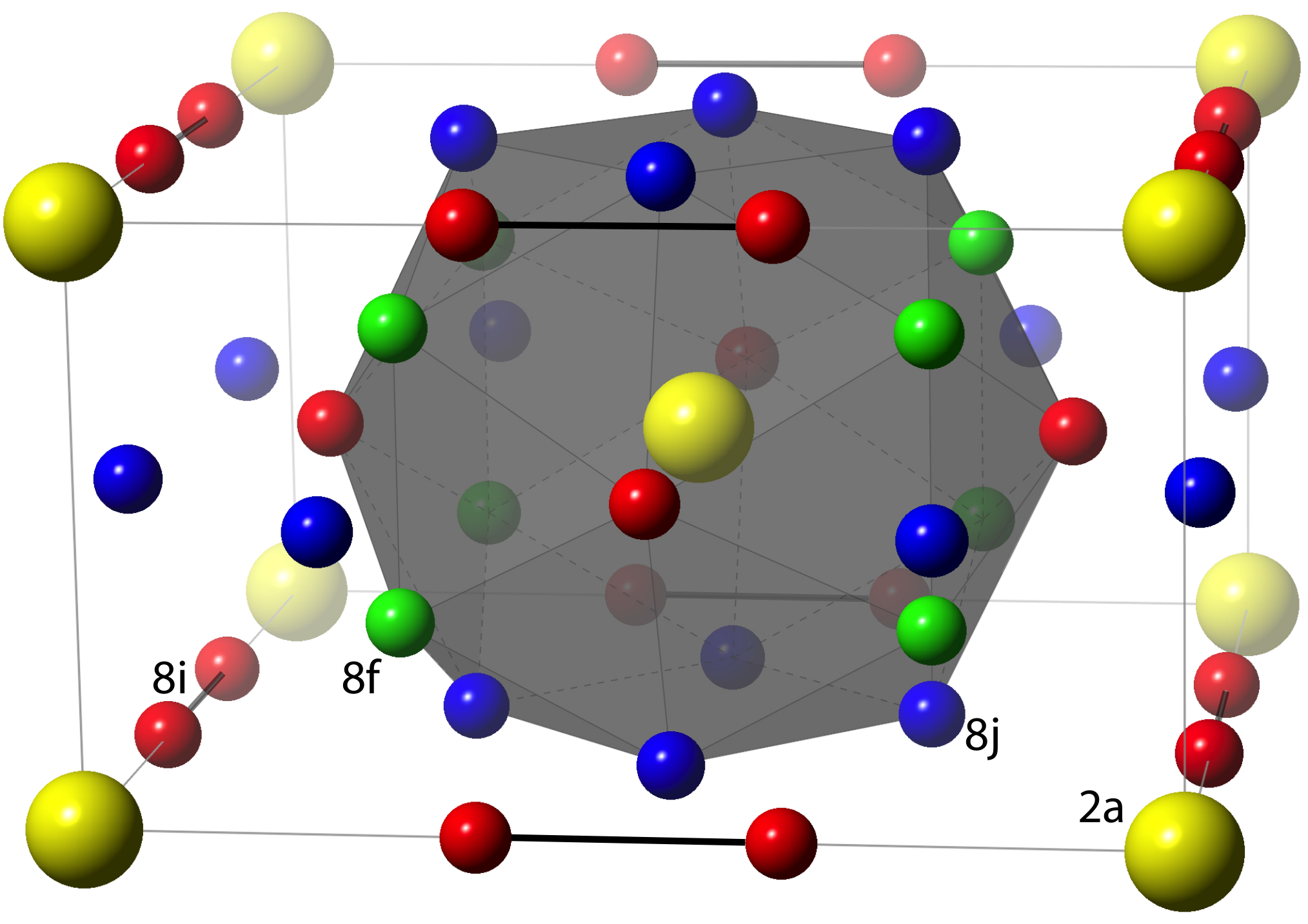
Fe11Ti has a body-center-tetragonal ThMn12-type ( space group, no.139) structure, which is closely related to the 1-5 and 2-17 - structures.[11] The primitive unit cell contains one formula unit (f.u.). As shown in Fig. 1, atoms occupy the site, while transition metal atoms are divided into three sublattices, (), () and (), each of which has fourfold multiplicities. The and sites bear a great similarity in their local environments with respect to the distribution of coordinated atoms,[37] whereas the sites, often referred to as dumbbell sites, form -Fe-Fe-- chains with atoms along the basal axes, instead of the axis, as in the 2-17 structure.[38] Ti atoms occupy nearly exclusively on the sites, however, the distribution of Fe and Ti atoms within the 8 sites is disordered.
To calculate Fe11Ti, we replace one of four Fe() atoms with Ti in the primitive cell of Fe12 and neglect the effect of the artificial Ti ordering introduced by using this unit cell. Although the symmetry is lowered by Ti substitution or the spin-orbit coupling (SOC) in the anisotropy calculation, we still use the notations of , , and sites for simplicity.
For Co doping, Mössbauer spectroscopy found that Co atoms preferentially occupy the sites in Y(Fe1-xCox)11Ti,[39] while the high-resolution neutron powder diffraction experiments concluded that Co atoms preferentially occupy sites in the sequence of .[40] For interstitial H, C, and N doping, neutron scattering has shown that dopants prefer to occupy the larger octahedral interstitial sites,[25, 15] which have the shortest distance from the rare-earth sites among all empty interstitial sites. In all our calculations, we also assume that H, C, or N atom occupies the sites.
II.2 Computational methods
Most magnetic properties were calculated using a standard linear muffin-tin orbital (LMTO) basis set[41] generalized to full potentials.[42] This scheme employs generalized Hankel functions as the envelope functions. For MAE calculation, the SOC was included through the force theorem.[43] The MAE is defined below as =, where and are the summation of band energies for the magnetization being oriented along the and directions, respectively. Positive (negative) corresponds to uniaxial (planar) anisotropy. It should be noted that, due to the presence of Ti in the primitive cell, the two basal axes become inequivalent, with -Ti-Fe-- chains along the direction and -Fe-Fe-- chains along the direction. and become different, which is an artifact introduced by using the small primitive cell and artificial ordering of Ti within the 8 sublattice.
We found that the direction is harder than the in YFe11Ti, and vice versa in YCo11Ti. is usually about the average of and . Thus, we use as the reference direction for the basal plane. A -point mesh is used for MAE calculations to ensure sufficient convergence; MAE in YFe11Ti changed by less than 3 when a denser mesh was employed. To decompose the MAE, we evaluate the on-site SOC matrix element and the corresponding anisotropy =. Unlike MAE, can be easily decomposed into sites, spins, and orbital pairs. According to second-order perturbation theory,[44, 45]
| (1) |
where indicates atomic sites. Equation (1) holds true for all compounds that we investigated in this paper. Hence, we use () to represent the site-resolved MAE. For simplicity, we write it as .
Exchange coupling parameters are calculated using a static linear-response approach implemented in a Green’s function (GF) LMTO method, simplified using the atomic sphere approximation (ASA) to the potential and density.[46, 47] The scalar-relativistic Hamiltonian was used so SOC is not included, although it is a small perturbation on ’s. In the basis set, orbitals are included for Ce, Y, Fe, and Co atoms, and orbitals are included for H, C, and N atoms. Exchange parameters are calculated using a -point mesh, and can be obtained by a subsequent Fourier-transforming. is estimated in the mean-field approximation (MFA) or random-phase approximation (RPA). See Ref. 46 for details of the methods to calculate .
For all magnetic property calculations, the effective one-electron potential was obtained within the local density approximation (LDA) to DFT using the parametrization of von Barth and Hedin.[48] However, with the functional of Perdew, Becke, and Ernzerhof (PBE) being better at structural relaxation for most of the solids containing elements,[49] we use it to fully relax the lattice constants and internal atomic positions in a fast plane-wave method, as implemented within the Vienna simulation package (VASP).[50, 51] The nuclei and core electrons were described by the projector augmented wave (PAW) potential[52] and the wave functions of valence electrons were expanded in a plane-wave basis set with a cutoff energy of up to 520 . All relaxed structures are then verified in FP-LMTO before the magnetic property calculations are performed.
III Results and discussion
III.1 structure
| Compounds | a11 1 Except for the hypothetical 1-12 compounds, Ti substitution in the 13-atom cell breaks the symmetry of CeFe12, and lattice parameters and become nonequivalent. The listed calculated is an average of and of the unit cell used in the calculation.(Å) | c(Å) | V(Å3) | Ref. | ||
|---|---|---|---|---|---|---|
| YFe11Ti (Exp.) | 8.480 | 4.771 | 343.08 | [53] | ||
| YFe11Ti | 8.472 | 4.720 | 338.78 | 0 | ||
| YFe12 | 8.447 | 4.695 | 334.94 | -1.1 | ||
| YFe11TiH | 8.457 | 4.732 | 338.43 | -0.10 | ||
| YFe11TiC | 8.517 | 4.834 | 350.67 | 3.51 | ||
| YFe11TiN | 8.563 | 4.791 | 351.31 | 3.70 | ||
| YCo11Ti (Exp.) | 8.367 | 4.712 | 329.87 | [54] | ||
| YCo11Ti | 8.328 | 4.673 | 324.08 | 0 | ||
| YCo12 | 8.268 | 4.655 | 318.21 | -1.81 | ||
| YCo11TiH | 8.343 | 4.688 | 326.30 | 0.68 | ||
| YCo11TiC | 8.396 | 4.767 | 336.08 | 3.70 | ||
| YCo11TiN | 8.436 | 4.716 | 335.59 | 3.55 | ||
| CeFe11Ti (Exp.) | 8.539 | 4.780 | 348.53 | [15] | ||
| CeFe11Ti | 8.524 | 4.670 | 339.35 | 0 | ||
| CeFe12 | 8.504 | 4.648 | 336.12 | -0.95 | ||
| CeFe11TiH | 8.498 | 4.738 | 342.13 | 0.82 | ||
| CeFe11TiC | 8.501 | 4.891 | 353.45 | 4.16 | ||
| CeFe11TiN | 8.570 | 4.809 | 353.17 | 4.07 | ||
| CeCo11Ti (Exp.) | 8.380 | 4.724 | 331.74 | [17] | ||
| CeCo11Ti | 8.360 | 4.657 | 325.46 | 0 | ||
| CeCo12 | 8.291 | 4.648 | 319.51 | -1.82 | ||
| CeCo11TiH | 8.359 | 4.694 | 327.94 | 0.76 | ||
| CeCo11TiC | 8.383 | 4.811 | 338.07 | 3.87 | ||
| CeCo11TiN | 8.442 | 4.735 | 337.44 | 3.68 |
Lattice constants and volumes are listed in Table 1, the calculated lattice constants are in good agreement with experiments. The strong Ti site preference on the site[3, 54, 15] had been interpreted in terms of atomic volume, coordination number, and enthalpy. It had been argued that enthalpy associated with and Ti, V, or Mo atoms are positive and sites have the smallest contact area with atoms. To identify quantitatively the site-preference effect, we calculated the total energy of CeFe11Ti with one Ti atom occupying at the 8, 8, or 8 sites, respectively, in the 13-atom primitive cell. The lowest-energy structure is the one with Ti atoms on the site. Energies are higher by 42 meVatom and 60 meVatom with Ti atom being on the and sites, respectively. Hence, Ti atom should have a strong preference to occupy the sites, as observed in the experiments.
In comparison to the hypothetical 1-12 compounds, the replacement of Fe or Co atoms with Ti increases volume by or , respectively. Experimentally, H doping slightly increases the volume by 1% in YFe11TiH, which is not observed in our calculation. The calculated volume of CeFe11TiH is 0.82% larger than CeFe11Ti. Calculations show that carbonizing and nitriding have a larger effect on volume expansion than hydrogenation and volume expansion is larger in Ce compounds than in Y compounds, both of which agree with experiments.
The total density of states of YFe11Ti and YFe11TiN compares reasonably well with previously reported LMTO-ASA calculations.[6] Figure. 2 shows the scalar-relativistic partial density of states (PDOS) projected on individual elements in YFe11Ti, YFe11TiH, YFe11TiC, and YFe11TiN. The Fe PDOS are averaged over 11 Fe atoms. The interstitial doping elements on sites hybridizes with neighboring and Fe() atoms. H- states hybridizes with neighboring Y and Fe() atoms at around -7 eV below the Fermi level in YFe11TiH. The C- and N- states have larger energy dispersion in YFe11TiC and YFe11TiN, respectively. The Fe states hybridized with interstitial elements, as shown in Fig. 2, are mostly from four (8) out of 11 Fe sites. Fe() sites are the furthest away from the interstitial sites and their hybridization with doping elements are negligible. The Ce compounds have a large -states above the Fermi level and share lots of similar PDOS features with the corresponding Y compounds below the Fermi level.
III.2 Magnetization, Exchange Couplings and
| Compound | (meV) | Ref. | ||||||||||||||
|---|---|---|---|---|---|---|---|---|---|---|---|---|---|---|---|---|
| () | 8 (Ti) | 8 | 8 | 8 | Y | K | () | () | ||||||||
| YFe12 | 24.20 | 0.61 | 24.81 | 7.57 | 4.91 | 5.10 | 1.34 | 689 | -38 | 1.40 | 1.34 | |||||
| YFe11Ti (Exp.) | 1920.6 | 524538 | 2.0 | [8, 11, 27, 19, 16] | ||||||||||||
| YFe11Ti | 19.75 | 0.60 | 20.35 | 5.29 | 7.17 | 6.70 | 6.61 | 1.43 | 727 | 0 | 1.93 | 1.83 | ||||
| YFe11TiH | 19.92 | 0.54 | 20.46 | 4.99 | 7.63 | 7.46 | 7.57 | 1.40 | 778 | 51 | 2.07 | 1.96 | ||||
| YFe11TiC | 20.64 | 0.55 | 21.19 | 5.51 | 8.58 | 8.83 | 8.66 | 1.67 | 884 | 157 | 0.95 | 0.87 | ||||
| YFe11TiN | 22.11 | 0.57 | 22.68 | 5.44 | 9.36 | 8.91 | 9.29 | 1.30 | 938 | 211 | 1.80 | 1.65 | ||||
| YCo11Ti (Exp.) | 14.215.7 | 10201050 | 0.7511 1 Measured at room temperature. | [19, 18] | ||||||||||||
| YCo11Ti | 14.42 | 0.82 | 15.24 | 3.93 | 10.50 | 10.13 | 11.13 | 1.45 | 1091 | 364 | 0.94 | 0.93 | ||||
| YCo12 | 18.42 | 0.90 | 19.32 | 12.52 | 13.12 | 13.84 | 1.66 | 1374 | 647 | 0.48 | 0.48 | |||||
| CeFe12 | 24.02 | 0.78 | 24.80 | 8.69 | 7.33 | 6.12 | 1.75 | 806 | 131 | 1.77 | 1.69 | |||||
| CeFe11Ti (Exp.) | 17.420.2 | 482487 | 1.311 1 Measured at room temperature.2.011 1 Measured at room temperature. | [18, 5, 15, 17, 55] | ||||||||||||
| CeFe11Ti | 19.19 | 0.72 | 19.91 | 4.69 | 6.26 | 7.04 | 5.95 | 2.16 | 675 | 0 | 2.09 | 1.98 | ||||
| CeFe11TiH | 20.24 | 0.77 | 21.01 | 4.67 | 6.87 | 7.42 | 7.04 | 2.30 | 736 | 61 | 2.03 | 1.90 | ||||
| CeFe11TiC | 19.84 | 0.73 | 20.57 | 5.45 | 9.86 | 8.62 | 8.62 | 3.44 | 908 | 233 | 1.09 | 0.99 | ||||
| CeFe11TiN | 21.48 | 0.67 | 22.15 | 5.51 | 9.09 | 8.53 | 8.99 | 1.09 | 905 | 230 | 1.78 | 1.62 | ||||
| CeCo11Ti (Exp.) | 10.912.5311 1 Measured at room temperature. | 920937 | Axial | [18, 17] | ||||||||||||
| CeCo11Ti | 13.77 | 1.32 | 15.09 | 4.07 | 10.40 | 9.38 | 10.94 | 3.76 | 1044 | 369 | 1.29 | 1.23 | ||||
| CeCo12 | 17.35 | 1.36 | 18.71 | 12.03 | 12.29 | 12.97 | 3.80 | 1286 | 611 | 1.24 | 1.24 | |||||
Intrinsic magnetic properties of each compound are listed in Table 2. Experimental magnetization and anisotropy values vary. The calculated magnetizations in YFe11Ti, YCo11Ti, and CeFe11Ti compare well with experiments. For CeCo11Ti, only a limited number of studies had been reported, and the calculated magnetization is larger than experimental ones. Ti spin moments couple antiparallel to those of Fe and Co sublattices, which is typical for the light and elements.[56] In CeFe11Ti, the Ce spin moments antiferromagnetically couple with the sublattice as expected.[57] Ce has a spin moment -0.7 and an orbital moment 0.3 with the opposite sign, which reflects Hund’s third rule. The calculated Fe spin moments on the individual sublattice have the magnitude in the sequence of ()()(), which agrees with previous experiments and calculations.[58] The dumbbell 8 sites have larger spin magnetic moments because of the relative larger surrounding empty volume and smaller atomic coordination number. The orbital magnetic moments calculated are larger in the Co-rich compounds than the Fe-rich compounds. MFA overestimated by about 200 K in Fe compounds and about 50100 K in Co compounds, respectively. RPA gives lower values, e.g., 489 K in YFe11Ti, and 461 K in CeFe11Ti, respectively. The experimental falls between the MFA and RPA values, and is much closer to the latter.
Ti additions decrease the magnetization by in Fe11Ti and Co11Ti relative to their 1-12 hypothetical counterparts. The magnetization reduction is not only due to the replacement of ferromagnetic Fe by antiferromagnetic Ti atoms (spin moment 0.54), but also the suppression of the ferromagnetism on the neighboring Fe sublattices. This is a common effect of doping early 3 or 4 elements on the Fe or Co sublattice.[56] On the other hand, the addition of the Ti atom barely affects the Ce moment. Interestingly, although magnetization decreased by upon the Ti addition, the calculated is even slightly higher in YFe11Ti than in YFe12. This is somewhat reflected in the experiments, in which no obvious dependence on Ti composition was observed in YFe11-zTiz over the homogeneous 1-12 phase composition range, 0.7 1.25.[11]
To understand this phenomenon, we investigated the effective exchange coupling parameters = and compare values in YFe12 and YFe11Ti. With Ti replacing one Fe atom, values increase for all sites except the pair of Ti-Fe dumbbell sites. The overall and the mean-field increase. The site-resolved effective exchange parameters for various compounds are listed in Table 2.
Figure 3 shows the magnetization as a function of the Co composition in YFe11Ti, with similar behavior to the Slater-Pauling curve. The maximum magnetization occurs at =0.2, while in experiments it is at =0.3.[19] Similarly, for Ce(Fe1-xCox)11Ti, the experimental maximum magnetization occurs at =0.10.15.[55] As shown in Table 2, the Co11Ti compounds have much larger than the corresponding Fe11Ti compounds, which agrees with experiments.[17]
All interstitial doping increases and in YFe11Ti and CeFe11Ti, and nitriding has the strongest effect. With H, C, and N doping, the calculated Curie temperature in YFe11Ti increases by 51, 157, and 211 K, respectively, which is consistent with experiments. values on all three sublattices increase with interstitial doping. Although DFT underestimats the volume expansion with H doping, the calculated is only slightly smaller than the experimental value. The calculated is larger with N doping than C doping, while their calculated volume expansions are similar. This indicates that both volume and chemical effects are important for the enhancement. To estimate qualitatively the relative magnitudes of the two effects, we calculate the of several hypothetical compounds related to YFe11TiN by removing the N atom in the unit cell or replacing it with H or C atoms, respectively. The calculated of those structures relative to YFe11Ti are 53, 80, and 169 K, respectively. Obviously, both volume and chemical effects contribute to the enhancement and the chemical effects of interstitial elements are in the sequence of NCH.
III.3 MAE in (Fe1-xCox)11Ti
As listed in Table 2, both YFe11Ti and YCo11Ti have uniaxial anisotropy. Calculated MAE in YFe11Ti is in good agreement with the experimental value. CeFe11Ti has a slightly larger MAE than YFe11Ti as found in experiments.[32, 15] The PBE functional (not shown) gives a smaller MAE than LDA in YFe11Ti and CeFe11Ti.
The Fe sublattice anisotropy may have a strong dependence on the composition of stabilizer atoms.[14] To understand how Ti affects the magnetic anisotropy and the origin of the nonmonotonic dependence of MAE on Co composition, we resolved MAE into sites by evaluating the matrix element of the on-site SOC energy.[45, 44] For intermediate Co composition, we investigate the MAE in YFe7Co4Ti and YFe3Co8Ti. We calculated the formation energy relative to YFe11Ti and YCo11Ti and found that YFe7Co4Ti has a formation energy =34 meVatom with four Co atoms on the sites and =28 meVatom with four Co atoms on the sites. Both values are lower than =10 meVatom, the formation energy of YFe8Co3Ti with all three Co atoms being on the sites. Hence, the site preference of Co atoms is 888, which agrees with the neutron scattering experiments.[40] For YFe3Co8Ti, we occupy another four Co atoms on the sites and the corresponding formation energy is 31 meVatom.
Figure 4 shows the total MAE values and their sublattice-resolved components, in YFe12, YFe7Co4Ti, YFe3Co8Ti and YCo11Ti. Obviously, Eq. (1) is well satisfied in all compounds and presents well the site-resolved MAE. The Y sublattice has a negligible contribution to anisotropy, as expected for a weakly magnetic atom, because the spin-parallel components of MAE contribution cancel out the spin-flip ones.[45] Sublattice-resolved MAE contributions in YFe12 shows 0, which agrees with the previous estimation in sign but differs in the order.[11] Considering Fe(8) sites have positive contributions to the uniaxial anisotropy in YFe12, one may expect that replacing Fe atoms by the Ti atoms on the site would decrease MAE. Interestingly, we found that YFe11Ti has even larger uniaxial anisotropy than YFe12. Anisotropies of all three sublattices become more uniaxial and 0 in YFe11Ti, which indicates that the introduction of Ti atoms modifies the electronic structure of neighboring sites and enhances their contribution to uniaxial anisotropy. Similarly, other compounds, such as YCo11Ti, CeFe11Ti, and CeCo11Ti, are also found to have MAE values larger than or similar to their corresponding hypothetical 1-12 counterparts.
The dependence of MAE on the Co composition is nonmonotonic and also found in other - systems.[59] As shown in Fig. 4, the calculated MAE reproduce the trend observed in experiment. For intermediate Co compositions, YFe7Co4Ti compound has planar anisotropy while YFe3Co8Ti compound has a very small uniaxial anisotropy. The 8 sublattice is the major contributor to the uniaxial anisotropy in YFe11Ti. With all four 8 Fe atoms being replaced by Co atoms in YFe7Co4Ti, becomes very negative. Moreover, and are also strongly affected and become negative. Further Co doping on sites changes and back to positive in YFe3Co8Ti. Finally, in YCo11Ti both and increase and becomes less planar and we have 0.
The nonmonotonic composition dependence is often interpreted by preferential site occupancy,[59] however, such an explanation is an oversimplification for a metallic system, such as Y(Fe1-xCox)11Ti. The MAE contributions from each sublattice may depend on the detailed band structure around the Fermi energy. The doping of Co on particular sites unavoidably affects the electronic structure of neighboring sublattices due to the hybridization between them, which changes the MAE contribution from neighboring sites. Obviously, as shown in Fig. 4, with a sizable amount of Co doping, the variation of anisotropy is a collective effect instead of a sole contribution from the doping sites.
Among three sublattices, the dumbbell 8 sites have the largest contribution to the uniaxial anisotropy in YCo11Ti, which we found also true in CeCo11Ti, and hypothetical YCo12 and CeCo12. It is interesting to compare the MAE contributions from Co sublattices in Co12 and Co17, in which the dumbbell Co sites have the most negative contribution to the uniaxial anisotropy.[38] In both cases, the moments of the dumbbell sites prefer to be perpendicular to the dumbbell bonds, which are along different directions in two structures, i.e., basal axes in the 1-12 structure and axis in the 2-17 structure. As a result, dumbbell Co sites have MAE contributions of opposite sign in two structures.
In a real sample, Co likely also partially occupies the and sites instead of exclusively only the 8 site. We investigate the scenario at the other extreme by assuming Co occupies the three sublattices with equal probability and calculate composition dependence of MAE using the virtual crystal approximation (VCA). Interestingly, the nonmonotonic behavior is also observed as shown in Fig. 5. The easy direction changes from uniaxial to in-plane and then back to uniaxial. The variations of each individual sublattice share a similarity with the trend shown in Fig. 4. With increasing of in Y(Fe1-xCox)11Ti, decreases and becomes negative while and become negative for the intermediate Co composition and then change back to positive at the Co-rich end. Thus, the nonmonotonic behavior is confirmed with or without considering preferential occupancy. The spin-reorientation transition[21] from axis to in-plane occurs in Y(Fe1-xCox)11Ti but not pure YFe11Ti,[21] which may relate to the fact that the competing anisotropies between three sublattices exist in Y(Fe1-xCox)11Ti while all three sublattices support the uniaxial anisotropy in YFe11Ti. As shown in Fig. 5(Top), MAE in Y(Fe1-xCox)11Ti barely changes or even slightly increases with a very small Co composition. A similar feature had been observed experimentally.[60] It is caused by the partial occupation of Co on sites in YFe11Ti. We found that replacing Fe atoms in YFe11Ti with Co atoms on the 8 sites increases the MAE.
It is commonly assumed that the MAE contributions from the sublattices are similar in - compounds with different , and such contributions are often estimated experimentally from measurements on corresponding yttrium compounds.[12] As shown in Fig. 5, MAE contributions from sublattices in YFe11Ti and CeFe11Ti are similar but not identical. All three sublattices have positive contributions to the uniaxial anisotropy and 0. However, magnitudes of each sublattice differ in two compounds, which suggest that the hybridization sites have with different atoms affects their contributions to the MAE. Unlike the Y sublattice in YFe11Ti, Ce provides a positive contribution to the uniaxial anisotropy in CeFe11Ti.
III.4 Effect of interstitial doping
Interstitial doping with N, C, and H affects the MAE from both of the Fe and sublattices.[30] As shown in Table 2, H doping barely changes or slightly increases the uniaxial anisotropy in YFe11Ti and CeFe11Ti while carbonizing and nitriding weaken the uniaxial anisotropy, which agrees with experiments.[27, 5] Simultaneous substitutional Co doping and interstitial doping with H, C, or N is of interest. Although the uniaxial anisotropy may not improve that much at the low temperature, the effect could be more significant at room temperature. For example, upon hydrogenation, a significant increase of with a factor 1.8 was observed in YFe9Co2Ti at room temperature.[60]
To our knowledge, simultaneous doping of Co and interstitial elements C and N atoms is not well studied. We calculated the MAE dependence on Co compositions in Ce(Fe1-xCox)11Ti with =H, C, and N, and results are shown in Fig. 6. The site preference of Co is not considered and VCA is used. The maximum of uniaxial anisotropy in Y(Fe1-xCox)11TiH is obtained at =0.1 while experiments found the maximum at YFe9Co2TiH.[60] For the Fe-rich CeCo11Ti, only H doping slightly increases the MAE, while C and N quickly decrease uniaxial anisotropy. For Y(Fe1-xCox)11Ti, it is unlikely we can have better uniaxial anisotropy (at least at low temperature) over the whole range of Co composition. Interestingly, for Co-rich Ce(Fe1-xCox)11Ti, interstitial C doping significantly improves the uniaxial anisotropy in Ce(Fe1-xCox)11Ti for 0.70.9. Considering the relative high Curie temperature on the Co-rich end, it has an attractive combination of all three intrinsic magnetic properties, , , and , for permanent magnet application.
IV Conclusion
Using DFT methods, the intrinsic magnetic properties of Fe11Ti-related systems were investigated for the effects of substitutional alloying with Co and interstitial doping with H, C, and N. All properties and trends were well described within the local density approximation to DFT. In comparison to the hypothetical YFe12, Ti quickly decreases the magnetization and increases the uniaxial magnetic anisotropy in YFe11Ti. The calculated Co site preference is in Y(Fe1-xCox)11Ti with , in agreement with neutron experiments. The enhancement of and due to Co doping and interstitial doping are in good agreement with experiments.
Compared with YFe11Ti, the calculated increases by 51, 157 and 211 K in YFe11Ti with =H, C, and N, respectively, with both volume and chemical effects contributing to the enhancement. We found that all three Fe sublattices promote uniaxial anisotropy in the sequence of in YFe11Ti, while competing contributions give in YCo11Ti. For intermediate Co composition, we confirm that the easy direction changes with increasing Co content from uniaxial to in-plane and then back to uniaxial. Substitutional doping affects the MAE contributions from neighboring sites and the nonmonotonic composition dependence of anisotropy is a collective effect, which can not be solely explained by preferential occupancy. The Ce sublattice promotes the uniaxial anisotropy in CeFe11Ti and CeCo11Ti. Interstitial C doping significantly increases the uniaxial anisotropy in Ce(Fe1-xCox)11Ti for , which may provide the best combination of all three intrinsic magnetic properties for permanent applications.
Acknowledgments
We thank B. Harmon, A. Alam, C. Zhou, and R. W. McCallum for helpful discussions. This work was supported by the U.S. Department of Energy ARPA-E (REACT 0472-1526). Ames Laboratory is operated for the U.S. DOE by Iowa State University under Contract No. DE-AC02-07CH11358.
References
- [1] R. McCallum, L. Lewis, R. Skomski, M. Kramer, and I. Anderson, Annual Review of Materials Research 44, 451 (2014).
- [2] A. Kusne, T. Gao, A. Mehta, L. Ke, M. Nguyen, K. Ho, V. Antropov, C. Wang, M. Kramer, C. Long, et al., Sci. Rep. 4 (2014).
- [3] Y. Yang, L. Kong, S. Sun, D. Gu, and B. Cheng, Journal of Applied Physics 63, 3702 (1988a).
- [4] K. Buschow, Journal of Magnetism and Magnetic Materials 100, 79 (1991).
- [5] Q. Pan, Z. Liu, and Y. Yang, Journal of Applied Physics 76, 6728 (1994).
- [6] A. Sakuma, Journal of the Physical Society of Japan 61, 4119 (1992).
- [7] W. Körner, G. Krugel, and C. Elsässer, Sci Rep 6, 24686 (2016).
- [8] Y. Yang, H. Sun, Z. Zhang, T. Luo, and J. Gao, Solid State Communications 68, 175 (1988b).
- [9] J. Franse and R. Radwański (Elsevier, Amsterdam, 1993), vol. 7 of Handbook of Magnetic Materials, pp. 307 – 501.
- [10] H. Li and J. Coey (Elsevier, Amsterdam, 1991), vol. 6 of Handbook of Magnetic Materials, pp. 1 – 83.
- [11] B. Hu, H. Li, and J. Coey, Journal of Applied Physics 67, 4838 (1990).
- [12] J. Coey, Journal of Magnetism and Magnetic Materials 80, 9 (1989).
- [13] F. De Boer, Y. Huang, D. De Mooij, and K. Buschow, Journal of the Less Common Metals 135, 199 (1987).
- [14] M. Solzi, L. Pareti, O. Moze, and W. David, Journal of applied physics 64, 5084 (1988).
- [15] O. Isnard, S. Miraglia, M. Guillot, and D. Fruchart, Journal of Alloys and Compounds 275-277, 637 (1998).
- [16] I. Tereshina, P. Gaczyński, V. Rusakov, H. Drulis, S. Nikitin, W. Suski, N. Tristan, and T. Palewski, Journal of Physics: Condensed Matter 13, 8161 (2001).
- [17] C. Zhou, F. Pinkerton, and J. Herbst, Journal of Applied Physics 115, 17C716 (2014).
- [18] K. Ohashi, H. Ido, K. Konno, and Y. Yoneda, Journal of applied physics 70, 5986 (1991).
- [19] J. Wang, N. Tang, B. Fuquan, W. Wang, W. Wang, G. Wu, and F. Yang, Journal of Physics: Condensed Matter 13, 1617 (2001a).
- [20] V. Sinha, S. Cheng, W. Wallace, and S. Sankar, Journal of magnetism and magnetic materials 81, 227 (1989).
- [21] S. Cheng, V. Sinha, B. Ma, S. Sankar, and W. Wallace, Journal of Applied Physics 69, 5605 (1991).
- [22] O. Moze, L. Pareti, and K. Buschow, Journal of Physics: Condensed Matter 7, 9255 (1995).
- [23] J. Wang, B. Fuquan, C. Yang, and F. Yang, Journal of the Magnetics Society of Japan 23, 459 (1999).
- [24] Y. Yang, X. Zhang, L. Kong, Q. Pan, and S. Ge, Applied physics letters 58, 2042 (1991a).
- [25] Y. Yang, X. Zhang, L. Kong, Q. Pan, S. Ge, J. Yang, Y. Ding, B. Zhang, C. Ye, and L. Jin, Solid State Communications 78, 313 (1991b).
- [26] D. Hurley and J. Coey, Journal of Physics: Condensed Matter 4, 5573 (1992).
- [27] Q. Qi, Y. Li, and J. Coey, Journal of Physics: Condensed Matter 4, 8209 (1992).
- [28] Z. Li, X. Zhou, and A. Morrish, Journal of Physics: Condensed Matter 5, 3027 (1993).
- [29] S. Nikitin, I. Tereshina, V. Verbetsky, and A. Salamova, International Journal of Hydrogen Energy 24, 217 (1999).
- [30] S. Nikitin, I. Tereshina, V. Verbetsky, and A. Salamova, Journal of Alloys and Compounds 316, 46 (2001).
- [31] D. Zhang, Z. Zhang, Y. Chuang, B. Zhang, J. Yang, and H. Du, Journal of Physics: Condensed Matter 7, 2587 (1995).
- [32] J. Coey, J. Allan, A. Minakov, and Y. Bugaslavsky, Journal of Applied Physics 73, 5430 (1993).
- [33] J. Chaboy, A. Marcelli, L. Bozukov, F. Baudelet, E. Dartyge, A. Fontaine, and S. Pizzini, Phys. Rev. B 51, 9005 (1995).
- [34] L. Nordström, O. Eriksson, M. Brooks, and B. Johansson, Phys. Rev. B 41, 9111 (1990).
- [35] O. Eriksson, L. Nordström, M. Brooks, and B. Johansson, Phys. Rev. Lett. 60, 2523 (1988).
- [36] A. Alam, M. Khan, R. W. McCallum, and D. D. Johnson, Applied Physics Letters 102, 042402 (2013).
- [37] Y. Wang, J. Shen, N. Chen, and J. Wang, Journal of Alloys and Compounds 319, 62 (2001b).
- [38] L. Ke, D. Kukusta, R. Mccallum, and V. Antropov, in IEEE Magnetics Conference (INTERMAG) (2015).
- [39] Z. Li, X. Zhou, and A. Morrish, Journal of Applied Physics 69, 5602 (1991).
- [40] J. Liang, Q. Huang, A. Santoro, J. Wang, and F. Yang, Journal of Applied Physics 86, 2155 (1999).
- [41] O. Andersen, Phys. Rev. B 12, 3060 (1975).
- [42] M. Methfessel, M. van Schilfgaarde, and R. A. Casali, in Lecture Notes in Physics, edited by H. Dreysse (Springer-Verlag, Berlin, 2000), vol. 535.
- [43] A. Mackintosh and O. Andersen, Electrons at the Fermi Surface (Cambridge University Press, Cambridge, England, 1980).
- [44] V. Antropov, L. Ke, and D. berg, Solid State Communications 194, 35 (2014).
- [45] L. Ke and M. van Schilfgaarde, Phys. Rev. B 92, 014423 (2015).
- [46] L. Ke, K. Belashchenko, M. van Schilfgaarde, T. Kotani, and V. Antropov, Phys. Rev. B 88, 024404 (2013).
- [47] L. Ke, M. van Schilfgaarde, and V. Antropov, Phys. Rev. B 86, 020402 (2012), Rapid communication.
- [48] U. von Barth and L. Hedin, Journal of Physics C: Solid State Physics 5, 1629 (1972).
- [49] P. Haas, F. Tran, and P. Blaha, Phys. Rev. B 79, 085104 (2009).
- [50] G. Kresse and J. Hafner, Phys. Rev. B 47, 558 (1993).
- [51] G. Kresse and J. Furthmüller, Phys. Rev. B 54, 11169 (1996).
- [52] G. Kresse and D. Joubert, Phys. Rev. B 59, 1758 (1999).
- [53] S. Obbade, D. Fruchart, M. Bououdina, S. Miraglia, J. Soubeyroux, and O. Isnard, Journal of Alloys and Compounds 253–254, 298 (1997).
- [54] O. Moze, L. Pareti, M. Solzi, and W. David, Solid State Communications 66, 465 (1988).
- [55] D. Goll, R. Loeffler, R. Stein, U. Pflanz, S. Goeb, R. Karimi, and G. Schneider, physica status solidi (RRL) – Rapid Research Letters 8, 862 (2014).
- [56] X. Zhao, M. Nguyen, W. Zhang, C. Wang, M. Kramer, D. Sellmyer, X. Li, F. Zhang, L. Ke, V. Antropov, et al., Phys. Rev. Lett. 112, 045502 (2014).
- [57] J. Trygg, B. Johansson, and M. Brooks, Journal of Magnetism and Magnetic Materials 104, 1447 (1992).
- [58] B. Hu, H. Li, J. Gavigan, and J. Coey, Journal of Physics: Condensed Matter 1, 755 (1989).
- [59] N. Thuy, J. Franse, N. Hong, and T. Hien, J. Phys. Colloques 49, 499 (1988).
- [60] E. Tereshina, I. Telegina, T. Palewski, K. Skokov, I. Tereshina, L. Folcik, and H. Drulis, Journal of Alloys and Compounds 404, 208 (2005).