Effect of Wideband Beam Squint on Codebook Design in Phased-Array Wireless SystemsThanks: This work has been supported by Huawei Technologies Co., Ltd.
Abstract
Analog beamforming with phased arrays is a promising technique for 5G wireless communication at millimeter wave frequencies. Using a discrete codebook consisting of multiple analog beams, each beam focuses on a certain range of angles of arrival or departure and corresponds to a set of fixed phase shifts across frequency due to practical hardware considerations. However, for sufficiently large bandwidth, the gain provided by the phased array is actually frequency dependent, which is an effect called beam squint, and this effect occurs even if the radiation pattern of the antenna elements is frequency independent. This paper examines the nature of beam squint for a uniform linear array (ULA) and analyzes its impact on codebook design as a function of the number of antennas and system bandwidth normalized by the carrier frequency. The criterion for codebook design is to guarantee that each beam’s minimum gain for a range of angles and for all frequencies in the wideband system exceeds a target threshold, for example 3 dB below the array’s maximum gain. Analysis and numerical examples suggest that a denser codebook is required to compensate for beam squint. For example, 54% more beams are needed compared to a codebook design that ignores beam squint for a ULA with 32 antennas operating at a carrier frequency of 73 GHz and bandwidth of 2.5 GHz. Furthermore, beam squint with this design criterion limits the bandwidth or the number of antennas of the array if the other one is fixed.
I Introduction
Two major directions are being explored to enhance radio frequency (RF) spectrum access, namely, reusing currently under-utilized frequency bands below roughly 6 GHz through dynamic spectrum access (DSA) and exploiting spectrum opportunities in higher frequencies, e.g., millimeter-wave (mmWave) bands [1, 2]. The total amount of spectrum that can be shared below 6 GHz is limited to hundreds of MHz, whereas mmWave bands can provide spectrum opportunities on the order of tens of GHz. However, the signals at mmWave frequencies experience significantly higher path loss than signals below 6 GHz [3].
Beamforming with a phased array having a large number of antennas is a promising approach to compensate for higher attenuation at mmWave frequencies while supporting mobile applications [4, 5, 6]. First, the short wavelength of mmWave allows for integration of a large number of antennas into a phased array of small size suitable for a mobile wireless device. Second, switched beamforming applies different sets of parameters to the phased array, allowing the beam direction to be electronically and quickly controlled, which enables steering for different orientations and tracking for mobility. In this paper, we consider switched analog beamforming with one RF chain using a phased array with phase shifters. For hybrid architectures, phased arrays can also be implemented by either phase shifters or switches [7].
Traditionally in a communication system with analog beamforming, the sets of phase shifter values in a phased array are designed at a specific frequency, usually the carrier frequency, but applied to all frequencies within the transmission bandwidth due to practical hardware constraint. Phase shifters are relatively good approximations to the ideal time shifters for narrowband transmission; however, this approximation breaks down for wideband transmission if the angle of arrival (AoA) or angle of departure (AoD) is away from broadside, because the required phase shifts are frequency-dependent. The net result is that beams for frequencies other than the carrier “squint” as a function of frequency [8] in a wide signal bandwidth. This phenomenon is called beam squint in a wideband system [9]. As we will see in the context of orthogonal division multiplexing (OFDM) modulation with multiple subcarriers, beam squint translates into array gains for a given AoA or AoD that vary with subcarrier index. To eliminate or reduce beam squint with hardware approaches, true time delay and phase improvement schemes have been proposed [10, 11]; however, these approaches are unappealing for mobile wireless communication due to combinations of high implementation cost, significant insertion loss, large size, or excessive power consumption.
Covering a certain range of AoA or AoD in switched beamforming requires a “codebook” consisting of multiple beams, with each beam determined by a set of beamforming phases [12, 13]. Usually, a minimum array gain is required for the codebook to cover the entire desired angle range [14], for example, 3 dB below the array’s maximum gain. A natural extension for a wideband system is to design the beamforming codebook to guarantee the minimum gain for all frequencies, even in the presence of beam squint. To the best of our knowledge, only [11] proposes a phase improvement scheme to reduce the effect of beam squint in beamforming codebook, but with high implementation cost of additional phase shifters and bandpass filters in mmWave frequency. By contrast, we propose developing denser codebooks to compensate for beam squint at the system level.
The main contributions of this paper are twofold. First, we model the beam squint for a uniform linear array (ULA) in a wireless communication system, and show that the usable beamwidth for each beam effectively decreases because of the beam squint. Therefore, the number of beams in the codebook must increase to counter this effect. Second, we develop a codebook design algorithm to enforce minimum array gain for all subcarriers in the wideband system. The bandwidth of the system is limited for a fixed number of antennas in the phased array; conversely, the number of antennas in the phased array is limited for a fixed bandwidth. The algorithm and conclusions also apply to frequencies other than mmWave and acoustic communication.
II System Model
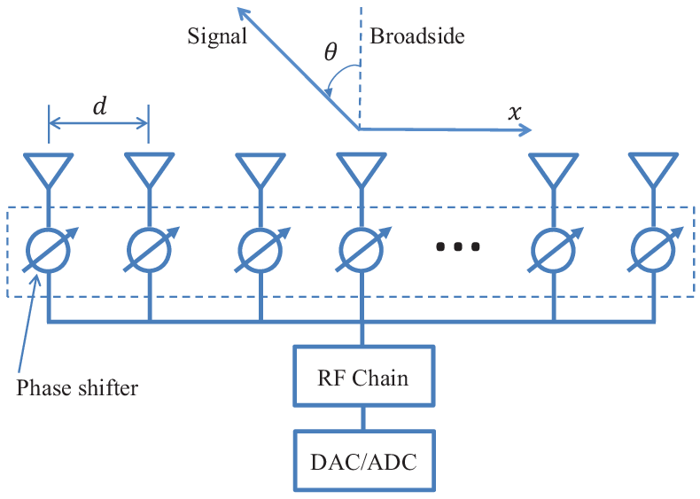
We consider a ULA as shown in Fig. 1. It could be the phased array of either a transmitter or receiver. In the array, there are identical and isotropic antennas, each connected to a phase shifter. The distances between two adjacent antenna elements are the same and are all denoted by . For simplicity, we also assume the phases of the phase shifters are continuous without quantization. The AoD or AoA is the angle of the signal relative to the broadside of the array, increasing counterclockwise. From [15], the ULA response vector is
| (1) |
where is the signal wavelength, and superscript indicates transpose of a vector. The effect of the phase shifters can be modeled by the beamforming vector
| (2) |
where is the phase of th phase shifter connected to the th antenna element in the array.
From [16], the array factors or array gains for both the transmitter and receiver have the same expression
| (3) |
where superscript denotes Hermitian transpose.
III Modeling of Beam Squint in a Phased Array
The analysis of the effect of beam squint is the same for a transmit or a receive array, so without loss of generality, we focus on the case of a receive array. Define the beam focus angle to be the AoA for which the beam has the highest gain for a given beamforming vector . The beamforming vector is traditionally designed for the carrier frequency. From (3), to achieve the highest array gain for a beam focus angle among all possible , the phase shifters should be
| (4) |
where is the wavelength of the carrier frequency. We call the beam with phase shifts described in (4) a fine beam, and we focus on the analysis of fine beams throughout the paper.
Based on (3), the array gain for a signal with frequency and AoA using beam focus angle is
| (5) |
where is the speed of light.

For a fixed array and beamforming vector, an example of the beam squint patterns for different frequencies is shown in Fig. 2. The beam focus angle for the carrier frequency is . The array gain for an AoA are different for different frequencies; in particular, the array gains of and for the beam focus angle are both smaller than that of .
For a wideband system, we express a subcarrier’s absolute frequency relative to the carrier frequency as
| (6) |
where is the ratio of the subcarrier frequency to the carrier frequency. Suppose the baseband bandwidth of the signal is . Then . Define the fractional bandwidth
| (7) |
with , so that . As a specific example, varies from 0.983 to 1.017 in a system with 2.5 GHz bandwidth at 73 GHz carrier frequency.
Let be the equivalent AoA for the subcarrier with coefficient . Comparing (8) to (5), can be expressed as
| (9) |
The variation of beam patterns for different frequencies in the wideband system can therefore be interpreted as the variation of AoAs in the same angle response for different subcarriers.
Usually, the beamforming array is designed such that . From (4) and (8),
| (10) |
Define
| (11) |
The array gain for frequency with in (10) becomes . Fig. 3 illustrates an example plot of . The main lobe is the lobe with the highest gain.

Let
| (12) |
to convert the angle space to the space. Correspondingly, , , and . The array gain of a fine beam in (10) then becomes
| (13) |
where . The maximum array gain is
| (14) |
For simplicity, we study the effect of beam squint in space. From (13), the effect of beam squint increases if the AoA is away from the beam focus angle, and it tends to increase as the beam focus angle increases.
IV Codebook Design
One widely used codebook design criterion is to require the array gain to be larger than a threshold for all subcarriers [14]. The threshold may vary for different system designs. In communication systems, the beam focus angle is determined by the beamforming vector . Define the beam coverage of as the set
| (15) |
where is the maximum targeted covered AoA/AoD of the codebook. The beam coverage of some beams is not contiguous in if is around -1 or 1. We only consider the beam whose beam range is contiguous.
Define the effective beamwidth as the measure of , i.e.,
| (16) |
where
A single beam can only cover a small range of angles in space. In communication systems with beamforming, multiple beams with different beam focus angles are utilized to cover the target angle range , forming a codebook . Suppose there are beams in the codebook to cover . The codebook has size and can be defined as
| (19) |
Denote as the set of all codebooks that meet the requirements of (19). There is an infinite number of codebooks in . Among them, we focus on the ones that achieve the minimum codebook size. Minimum codebook size is defined as
| (20) |
The threshold can be different for different system requirements. For illustration, we choose such that
| (21) |
where is defined in (14). The analysis of other thresholds is similar.
IV-A Codebook Design without Considering Beam Squint
Define beam edges as the points with in the main lobe whose array gain is . There are two beam edges, one on the left side and one on the right side, denoted as and , respectively. The selected in (21) is 3 dB below the maximum array gain . The corresponding beamwidth is called the 3 dB beamwidth, denoted as in space. For consecutive beam coverage, the beamwidth is the distance between the two beam edges, i.e.,
| (22) |
According to [15],
| (23) |
which is a constant independent of . It is worth stressing that the beamwidth in space is not fixed, and depends on .
To design a codebook with the minimum codebook size, we simply tile the beam coverages over without overlap. If the effect of beam squint is not considered, all beams have the same beamwidth as shown in (23), and the minimum codebook size
| (24) |
where denotes the well-known ceiling function.
Even for the same , there could be multiple codebook designs. Among them, we are more interested in the ones that are symmetric relative to broadside. A codebook design method for minimum codebook size without considering the beam squint is shown in Algorithm 1.
IV-B Beam Pattern with Beam Squint
As analyzed in the previous section, the array gains of some subcarriers are smaller than that of the carrier frequency when . To guarantee a minimum array gain for all the subcarriers, the beam range is reduced.
Since determines the beam focus angle , and can be used interchangeably. Define
| (25) | ||||
| (26) |
First, we study the case for , which gives us
| (27) | ||||
| (28) |
where and indicate the left edge and the right edge of the beam with beam focus angle when there is no beam squint, i.e., . Set in (15), and we have
| (29) | |||
| (30) |
we have
| (31) | ||||
| (32) | ||||
| (33) |
Similarly, for , we can obtain
| (34) | ||||
| (35) |
In considering effect of beam squint, the effective beamwidth for a beam with focus angle is
where is calculated with (31) and (32), or (34) and (35) if ; otherwise, is calculated with (32) and (34). If , is not fixed, and it is a linear function of for fixed .
Theorem 1.
If the number of antennas in the array is fixed, the fractional bandwidth is upper bounded by
| (38) |
Conversely, if the fractional bandwidth is fixed, the number of antennas in the array is upper bounded by
| (39) |
where is a floor function.
IV-C Codebook Design with Beam Squint
Again, to achieve the minimum codebook size, the beam coverages in the codebook should have as little overlap as possible. Algorithm 2 shows one method to design a codebook that achieves minimum codebook size with beams symmetric to broadside. Before running the algorithm, it is not clear whether the codebook contains an odd or an even number of beams that achieve the minimum codebook size. Procedure 1 in Algorithm 2 designs an odd-number codebook, denoted as ; Procedure 2 designs an even-number codebook, denoted as . For aligning the beams on the right of the broadside, of the beam with smaller beam focus angle is equal to of the beam with larger beam focus angle. The first determined beam in Algorithm 2 has .
Either or achieves the minimum codebook size. The minimum codebook size is also calculated in Algorithm 2, i.e.,
| (40) |
V Numerical Result
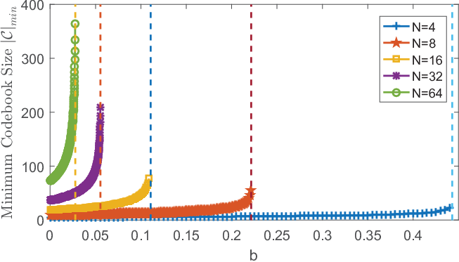
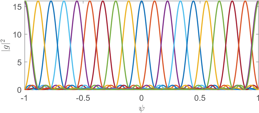
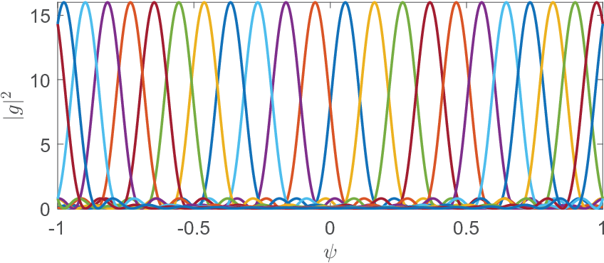
Fig. 5 and 5 show examples of codebook designs for the minimum codebook size without and with considering beam squint, respectively, for , and . denotes that the maximum targeted covered AoA/AoD of the codebook is . If beam squint is considered, the minimum codebook size increases. The beams are denser for higher focus angles, because of the larger reduction of effective beamwidth for a larger beam focus angle as shown in (IV-B). In the two figures, the fractional bandwidth corresponds to GHz and GHz. The minimum codebook size in the examples for a ULA is increased by 15.8% compared to that without considering beam squint, and it is increased by 54% for a ULA with the same .
Fig. 6 illustrates examples of the minimum codebook size as a function of fractional bandwidth for , i.e., the maximum targeted covered AoA/AoD of the codebook is . is equivalent to not considering beam squint. For all , as increases, increases, and is upper bounded for fixed , confirming Theorem 1. As approaches to its unreachable upper bound , increases significantly. If , the effective beamwidth of the beam with , ; therefore, . If , no codebook exists.
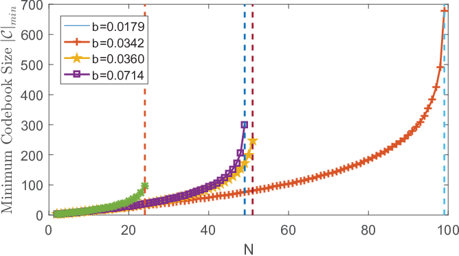
Fig. 7 shows examples of the minimum codebook size as a function of the number of antennas for , i.e., the maximum targeted covered AoA/AoD of the codebook is . increases as increases. is upper bounded by as described in (39). When goes beyond the upper bound, no codebook exists. The maximum array gain only depends on . Therefore, the maximum array gain is also upper bounded.
VI Conclusion
We analyzed the effect of beam squint in analog beamforming with a phased array implemented via phase shifters as well as its influence on codebook design. Overall, the effect of beam squint increases if the AoA/AoD is away from the beam focus angle, and it tends to increase as AoA/AoD increases. We also developed an algorithm to compensate for the beam squint in codebook design. Beam squint increases the codebook size if the minimum array gain is required for all subcarriers in the wideband signal. The fractional bandwidth is upper bounded for fixed number of antennas; the number of antennas in the phased array is correspondingly upper bounded for fixed fractional bandwidth.
References
- [1] M. Cai and J. N. Laneman, “Database- and sensing-based distributed spectrum sharing: Flexible physical-layer prototyping,” in Proc. Asilomar Conf. Signals, Systems, and Computers, Monterey, CA, Nov. 2015, pp. 1051–1057.
- [2] O. El Ayach, S. Rajagopal, S. Abu-Surra, Z. Pi, and R. W. Heath, “Spatially sparse precoding in millimeter wave MIMO systems,” IEEE trans. Wireless Commun., vol. 13, no. 3, pp. 1499–1513, 2014.
- [3] T. S. Rappaport, Wireless communications: principles and practice, 2nd ed. Upper Saddle River, NJ: Prentice Hall, 2002.
- [4] H. Huang, K. Liu, R. Wen, Y. Wang, and G. Wang, “Joint channel estimation and beamforming for millimeter wave cellular system,” in Proc. IEEE Global Commun. Conf. (GLOBECOM), 2015, pp. 1–6.
- [5] S. Hur, T. Kim, D. J. Love, J. V. Krogmeier, T. A. Thomas, and A. Ghosh, “Millimeter wave beamforming for wireless backhaul and access in small cell networks,” IEEE Trans. Commun., vol. 61, no. 10, pp. 4391–4403, 2013.
- [6] R. W. Heath Jr, N. Gonzalez-Prelcic, S. Rangan, W. Roh, and A. Sayeed, “An overview of signal processing techniques for millimeter wave MIMO systems,” IEEE J. Sel. Topics Signal Process., vol. 10, pp. 436–453, 2016.
- [7] R. Méndez-Rial, C. Rusu, N. González-Prelcic, A. Alkhateeb, and R. W. Heath, “Hybrid mimo architectures for millimeter wave communications: Phase shifters or switches?” IEEE Access, vol. 4, 2016.
- [8] R. J. Mailloux, Phased array antenna handbook, 2nd ed. Norwood, MA: Artech House, 2005.
- [9] S. kasra Garakoui, E. Klumperink, B. Nauta, and F. E. van Vliet, “Phased-array antenna beam squinting related to frequency dependence of delay circuits,” in Proc. 41th European Microwave Conf., Manchester, UK, Oct. 2011.
- [10] M. Longbrake, “True time-delay beamsteering for radar,” in Aerospace and Electronics Conference (NAECON), 2012 IEEE National. IEEE, 2012, pp. 246–249.
- [11] Z. Liu, W. Ur Rehman, X. Xu, and X. Tao, “Minimize beam squint solutions for 60 GHz millimeter-wave communication system,” in Proc. IEEE 78th Veh. Tech. Conf. (VTC 2013-Fall). IEEE, 2013, pp. 1–5.
- [12] J. Song, J. Choi, and D. J. Love, “Codebook design for hybrid beamforming in millimeter wave systems,” in Proc. 2015 IEEE Int. Conf. on Commun. (ICC). IEEE, 2015, pp. 1298–1303.
- [13] Q. Cui, H. Wang, P. Hu, X. Tao, P. Zhang, J. Hamalainen, and L. Xia, “Evolution of limited-feedback CoMP systems from 4G to 5G: CoMP features and limited-feedback approaches,” IEEE Veh. Technol. Mag., vol. 9, no. 3, pp. 94–103, 2014.
- [14] Z. Xiao, T. He, P. Xia, X.-G. Xia et al., “Hierarchical codebook design for beamforming training in millimeter-wave communication,” IEEE Trans. Wireless Commun., vol. 15, no. 5, pp. 3380–3392, 2016.
- [15] S. J. Orfanidis, Electromagnetic waves and antennas. New Brunswick, NJ: Rutgers University, 2002.
- [16] C. A. Balanis, Antenna theory: analysis and design, 4th ed. Hoboken, NJ: John Wiley & Sons, 2016.