∎
Refining Geometry from Depth Sensors using
IR Shading Images
Abstract
We propose a method to refine geometry of 3D meshes from a consumer level depth camera, e.g. Kinect, by exploiting shading cues captured from an infrared (IR) camera. A major benefit to using an IR camera instead of an RGB camera is that the IR images captured are narrow band images that filter out most undesired ambient light, which makes our system robust against natural indoor illumination. Moreover, for many natural objects with colorful textures in the visible spectrum, the subjects appear to have a uniform albedo in the IR spectrum. Based on our analyses on the IR projector light of the Kinect, we define a near light source IR shading model that describes the captured intensity as a function of surface normals, albedo, lighting direction, and distance between light source and surface points. To resolve the ambiguity in our model between the normals and distances, we utilize an initial 3D mesh from the Kinect fusion and multi-view information to reliably estimate surface details that were not captured and reconstructed by the Kinect fusion. Our approach directly operates on the mesh model for geometry refinement. We ran experiments on our algorithm for geometries captured by both the Kinect I and Kinect II, as the depth acquisition in Kinect I is based on a structured-light technique and that of the Kinect II is based on a time-of-flight (ToF) technology. The effectiveness of our approach is demonstrated through several challenging real-world examples. We have also performed a user study to evaluate the quality of the mesh models before and after our refinements.
Keywords:
RGB-D Sensor Kinect infrared IR geometry refinementshading image shape from shading1 Introduction
Over the past few years, Microsoft Kinect11 1 http://www.microsoft.com/en-us/kinectforwindows/ has become a popular input device in depth map acquisition for human pose recognition [39], 3D reconstruction [19], robotics [21] and many other applications [24]. The Kinect I utilizes active range sensing by projecting a structured light pattern, i.e. a speckle pattern, on a scene in the infrared (IR) spectrum22 2 Strictly speaking, it captures a range between 800 and 2500, which belong to the near infrared band. For simplicity, we abbreviate the band as the IR band in this paper.. By analyzing the displacement of the speckle pattern, a depth map of the scene can be estimated. In the Kinect II, although the underlying technique for depth map acquisition is based on a time-of-flight (ToF) technology, the Kinect II still retains the IR projector and IR camera for the Kinect to capture images under dark environments.
|
publication |
color camera |
depth camera |
auxiliary lights |
light model |
variables to be optimized | |
| Nehab [28] | 05 | DP | vertex position | |||
| Hernandez [14] | 08 | DP | vertex position | |||
| Wu [43] | 11 | SH | vertex position | |||
| Zhang [47] | 12 | DP | depth map | |||
| Park [33] | 13 | DP | displacement map | |||
| Han [12] | 13 | QF | surface normal | |||
| Yu [46] | 13 | SH | surface normal | |||
| Wu [44] | 14 | SH | vertex position | |||
| Zollhofer [49] | 15 | SH | position of voxel | |||
| Or-El [30] | 15 | SH | depth map | |||
| Bohme [3] | 10 | NP | depth map | |||
| Haque [13] | 14 | DP | depth map | |||
| Chatterjee [5] | 15 | DP | surface normal | |||
| Ours | – | NP | vertex displacement |
The success of the Kinect relies heavily on the usage of the narrow-band IR camera, which filters out most of the undesired ambient light, making the depth acquisition robust to natural indoor illumination. Although the IR camera is one of the key components to the success of the Kinect, after the depth acquisition, these IR images are discarded and not used in any post-processing applications. In this paper, we show that the IR camera of the Kinect is not only useful in the depth measurement, but also useful for capturing shading cues of a scene that allow higher quality reconstruction than the Kinect fusion [19], which only uses the estimated depth map for 3D reconstruction.
We analyzed the properties of the light emitted by the IR projector of the Kinect and found that the projector light can be approximately modeled by a near point light source with the light falloff property [25], where its illumination falls off with distance according to the inverse square law. With the Lambertian BRDF assumption about the scene materials in the captured IR spectrum, we define a near point light IR shading model that describes the captured intensity as a function of surface normals, albedo, lighting direction, and distance between a light source and surface points. The proposed model has an ambiguity between the normals and distance estimations using a single shading image. Therefore, we utilize an initial 3D mesh from the Kinect fusion and shading images from different view points. Our approach operates directly on the 3D mesh and optimizes the geometry refinement process subject to the shading constraint of our model. The result is a high quality mesh model that captures surface details, which were not reconstructed by the Kinect fusion. Thanks to the usage of the Kinect IR camera, our approach is also robust to indoor illumination and works well in both dark rooms and natural lighting environments. Furthermore, we have also found that for many materials with colorful albedo in the visible spectrum, the objects appear to have an uniform albedo in the IR spectrum. This observation allows us to use a simple technique to estimate surface albedo with reliable accuracy. Our approach does not require any additional cameras nor complicated light setups, making it useful in practical scenarios as an add-on to enhance reconstruction results from the Kinect fusion. Since the speckle pattern in the Kinect I is hardwired, we use a broad spectrum light bulb to approximate the IR projector light of the Kinect I with calibration. In the Kinect II, which uses a ToF technology, the inherent IR light source allows us to get a shading image without the additional light bulb.
This paper extends our previous work published in [6]. Specifically, the major benefits of using IR shading images for geometry refinement are further analyzed. We have also provided additional technical details in the albedo estimation and geometry optimization. To demonstrate the flexibility of our algorithm, results using only a single depth map and an IR image pair is also included. Similar to the Kinect I, the sensor characteristics of the Kinect II are also covered and the refined results from both sensors are displayed. To verify the effectiveness of our method, we conduct both a quantitative error measure and a qualitative user study. The rendered shading images from the meshes of the Kinect fusion and our method are compared to the input IR shading image. It measures how accurately our refined mesh models follow the photometric cues of the IR shading image. The user study also demonstrate improvements in terms of the visual quality of our refined mesh model.
2 Related Works
In the recent decade, depth measurement devices, such as the Kinect or ToF cameras, have allowed users to easily acquire a depth map of the scene at a low cost. However, the depth map usually contains holes and noisy measurements, which makes it less useful when a high quality depth map is required. Utilizing the additional RGB image, methods in [45, 8, 31, 32, 37] define a smoothness cost according to the image structures in the RGB image for depth map refinement, but their approaches do not use any shading information to potentially improve the depth quality.
Many literatures utilize shading or surface normal cues for the enhancement of rough geometry. Nehab et al. [28] refines a depth map by enforcing orthogonality between the surface gradient of the depth and surface normal acquired from photometric stereo [17, 25, 15]. Recently, Haque et al. [13], extends the work of [28] by utilizing IR images instead of color images. Work in [27] utilizes a giga-pixel camera to estimate ultra high resolution surface normals from photometric stereo to refine a low resolution depth map captured by using a structured light. B¨ohme et al. [3] uses shading information to improve depth map from a ToF camera. In [47, 29], they use normals from photometric stereo to refine a depth map with additional consideration to depth discontinuities [47] and the first-order derivative of surface normals [29]. Recent works by [12, 46, 44] propose to use shape-from-shading [16, 18] from an RGB image to estimate surface details for depth map refinement. In [41], high quality facial shape is generated using photometric cues of the color video sequences. In [38], photometric normals are obtained from a collection of internet photos with a linear approximation of the camera response functions, and then 3D shape of the object is refined.

 |
In 3D mesh refinement methods, the start typically consists of a rough 3D mesh model estimated by using stereo matching [35], visual hull [14], structure from motion [26], or Kinect fusion [19]. Similar to 2D depth map refinement, Hernandez et al. [14] demonstrate a two-way stage that estimates light directions and refines mesh model to have an estimated surface normal direction. Lensch et al. [23] introduce a generalized method for modeling non-Lambertian surfaces by using wavelet-based BRDFs and use it for mesh refinement. Vlasic et al. [42] integrate per-view normal maps into partial meshes, then deforms them using thin-plate offsets to improve the alignment while preserving geometric details. Wu et al. [43] use the multi-view stereo to solve the shape-from-shading ambiguity. They demonstrate high-quality 3D geometry under arbitrary illumination but assume the captured objects contain only a single albedo. Park et al. [33] refine 3D mesh in parameterized space and demonstrate state-of-the-art quality in geometry refinement results using normals from photometric stereo. Recently, Delaunoy et al. [7] propose a dense 3D reconstruction technique that jointly refines the shape and the camera parameters of a scene by minimizing the photometric reprojection error between a generated model and the observed images. Also Fanello et al. [9] propose a method for recovering the dense 3D structures of human hands and faces. They use hybrid classification-regression forests to learn how to map near infrared intensity images to absolute, metric depth in real-time.
Comparing our work to the previous works, especially for the 3D mesh refinement methods, most of them utilize photometric stereo to estimate normal details. Although high-quality surface details can be estimated by photometric stereo, as demonstrated in the experimental setting in [14, 42, 33], they require control over the environment’s illumination. In contrast, our work utilizes the Kinect IR camera, which makes our approach robust to natural indoor illumination as shown in Fig. 1. In addition, we define a near point light shading model that fits perfectly to our problem setting to utilize instead of a directional light source for normal estimation. Since our work directly operates on the mesh model, our approach is also efficient and effective in mesh model refinements.

3 IR Shading Images
In this section, we first analyze the IR images captured by the Kinect I and Kinect II. The inverse square law property of the IR light source is verified. The benefit of using IR images for simplifying albedo estimation in a scene is also analyzed. After that, we define our near point source IR light shading model. A radiometric calibration technique based on our IR shading model is also presented.
3.1 Kinect IR Images
We verify the invariability of Kinect IR images under different indoor lighting conditions. In Fig. 2, we block the Kinect IR projector and then capture IR images under ambient light and dark room environment. The RGB image pairs in (a) show enormous intensity differences under the two different lighting conditions, but the IR image pairs in (b) are almost identical. Next, we put a wide spectrum light source and then capture the RGB and IR images again under the same ambient light and dark room environment. Again, enormous intensity differences are shown in RGB image pairs in (c), while the IR image pairs in (d) have almost no difference. This example shows that common indoor lighting conditions do not cover the IR spectrum captured by the Kinect IR camera. Unless a wide spectrum light source is presented in a scene, the Kinect IR images is unaffected by ambient lighting.
In addition to the invariant indoor ambient light characteristic, the chromatic variations of textures in the visible spectrum appear to have a uniform albedo in the IR spectrum. In Fig. 3, we capture the same scene with a color camera and an IR camera. Textures on the mug, the towel, and the fabric appear to have uniform color in the IR spectrum, whereas, black ink is visible in both the visible and IR spectrum. This property is further analyzed by Salamati et al. [34]. They captured images of many different types of materials in the visible and near IR spectrum. The paper analyzed luma, intensity, and color information of images in the two different spectrum and revealed that many pigments used to colorize materials appear to be transparent in the near IR spectrum. Based on this analysis, we can simplify the albedo estimation by assuming that the same materials have the same albedo in the IR spectrum. This allows us to impose a smoothness regularization in the albedo estimation.
Our third analysis verifies the inverse square law property of the Kinect IR projector, a near point light source. We capture IR images at different distances of a white wall. Since we capture various images at different depths, we have observed that the number of total pixels grows too much for curve fitting (Each ROI contains 40k pixels (200 x 200), at least 10 images are used, results in 400k pixels). Therefore, for an efficient computation, we obtained the median intensity that is the representative intensity value for each image. Fig. 4 shows the captured IR image33 3 The IR image is radiometrically calibrated. and the region of median intensity with the red box. The decay of observed intensity follows the inverse square law.
 |
 |
||
| (a) | (b) | (c) | (d) |
3.2 Near IR Light Shading Model
Following the analyses from the previous section, we define the observed pixel intensity in the IR image as follows:
| (1) |
where is the index of a 2D pixel (which will also be used as an index for the corresponding 3D vertex in Sec. 4 ), is the global brightness, is the albedo of the surface, is the surface normal, is the lighting direction, and is the distance between the surface point and the light source. is the coefficient of the nonlinear radiometric parameter. Here, we assume the captured materials in the IR spectrum follow the Lambertian BRDF model. The inverse square term is added to account for the light falloff property along with the distance.
Since the effect of indoor ambient lights to the IR image is subtle, we regard . Since different pairs of and can produce identical intensity assuming known albedo and lighting direction, we utilize the initial mesh from the Kinect and multiple view point information to resolve this ambiguity. In Sec. 4, we will show that this shading model is an effective constraint for geometry refinement.
 |
 |
 |
| (a) | (b) | (c) |
 |
3.3 Radiometric Calibration of IR camera
We note that the responses of the Kinect IR camera is not strictly linear to the luminance of incoming light. Therefore, we need to radiometrically calibrate the Kinect IR camera. In previous works for radiometric calibration [11], multiple different exposure images can be easily captured for calibration. However, the Kinect IR camera can only capture a single exposure image. In addition, there is no calibration pattern for IR camera calibration. Here, we propose a radiometric calibration method which makes use of multiple photometric observations of a known geometry to estimate the camera response function (CRF) of the Kinect IR camera.
We use a white Lambertian sphere as shown in Fig. 5 (a) for our calibration. The white sphere has a known geometry and complete observation of surface normals in every direction. We use the Kinect fusion to obtain a base mesh of the sphere, and then capture the IR shading images of the sphere. Since the geometry, the distance, the lighting direction, and the albedo are known for this calibration object, we can synthetically render a predicted observation using Eq. (1). By comparing the measured intensities, , with the predicted intensities, , we can estimate the CRF, , by fitting a curve that minimizes the least square errors, , as illustrated in Fig. 5 (b) and (c). Here, we assume that is a gamma function where . The RANSAC algorihm [10] with 1000 sample points and iterations is used for robust fitting. In our estimation, we find that the gamma value is approximately equal to 0.8 for the Kinect I and 0.87 for the Kinect II.
To validate the effectiveness of the radiometric calibration step, we provide an additional experiment. First, we prepare two sets of input images that are processed with or without gamma correction. Second, we individually perform mesh refinement using different image sets. Here, the same parameters are used for the comparison. As shown in Fig. 6, the refined mesh looks nicer when our radiometric calibration step is applied a priori.
4 Geometry Refinement
This section includes our vertex optimization method for geometry refinement. We begin this section with mesh preprocessing and surface albedo estimation of the geometry. After that, we describe our mesh refinement process.
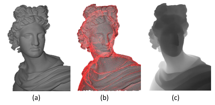
We denote , the -th vertex on the base mesh, , the neighboring vertices that directly connect to , is the intrinsic camera matrix for the IR cameras in the depth sensors and are the extrinsic projection matrices of the camera poses from the -th view. The image coordinate of vertex that is projected on the -th view is computed, . We also define which represents the visibility of on the -th view. Figure 10 shows an example of vertices projection on one of the input shading images.
 |
4.1 Mesh Preprocessing
Our mesh optimization controls vertex positions along with surface normal directions. For better convergence of the optimization and avoidance of mesh flipping, the initial mesh needs to be smooth enough and the vertices be uniformly distributed.
If a rough mesh is obtained from Kinect fusion [19], the mesh is already smooth because the integrated depth in a voxel grid suppresses depth noise. In this case, We only apply the remeshing technique [40] to resample vertex positions uniformly as shown in Fig. 7. The number of vertices are set to be about 100-200K which does not affect the initial geometry while allowing us to recover fine geometry details that were not reconstructed by the Kinect fusion. On the other hand, when a rough mesh is obtained from a single depth map, we apply joint-bilateral filtering [22] on the depth map to suppress depth noise. As a guidance image for the joint-bilateral filtering, we utilize the corresponding IR shading images.
4.2 Albedo Estimation
Global Albedo Since we use IR images, if a target object is made of the same material without different types of colorant, we assume the surface albedo to consist of a single value. This assumption is valid based on our analyses described in Sec. 3.1. Under this assumption, we estimate the surface albedo of vertices globally, using the inversion of Eq. (1). Given the measured intensity, , initial normals and the initial depth map from the projected mesh model and the known lighting direction, , we can obtain:
| (2) |
where is the total number of shading images, is the total number of vertices, and is a normalization factor. The undesired effect of cast shadow and specular saturation is handled by dropping the measurements where intensity values are either too small or too large.
 |
Multiple Albedo When a captured object has multiple albedos (multiple materials) in IR images, we compute the albedos on the vertices and group them in the 3D mesh. We begin with estimating the vertex-wise albedos by dividing the captured IR image with the rendered shading image as Eq. (3).
| (3) |
After estimating the local albedo, we group the local albedos using K-means clustering [20] and multi-label optimization [4]. Before grouping the albedos, the number of groups, K is decided via principal component analysis (PCA). The dominant directions of feature space are computed and we set K for capturing more than 95% of the feature space. The feature space consists of vertex positions and local albedos () where the parameter normalizes the features. After K-means clustering, we improve the albedo grouping via multi-label optimization as follows:
| (4) |
where is a vertex index, are the neighboring vertices of , and is the label for grouping. The initial labels from K-means clustering are used for the data term and we set the neighboring constraint based on our mesh connectivity.
Fig. 8 shows an example of our albedo grouping. In (c), our previous work shows a noisy result which is caused by specularity in the flowerpot. In contrast, we see that the noisy regions are improved and the result becomes more reliable in (d). This process gives us a more reliable albedo estimation.
4.3 Mesh Optimization
We refine the initial mesh model by searching for the optimal displacement of vertex along its normal direction. The refinement is subject to the shading constraint from the Kinect IR images. We define our cost function as follows:
| (5) | |||||
| (6) | |||||
| (7) | |||||
| (8) |
where denotes the displacement of vertices which we want to optimize, and is the normal direction of the -th vertex projected on the -th view. Our cost function is composed of a data term , a smoothness term , and a regularization term . The relationship among the variables are illustrated in Figure 9.
The data term in Eq. (6) is designed according to the near light IR shading model described in Sec. 3.2. At the beginning of our refinement, the IR camera centers are initially estimated in the world coordinate. Since we utilize the calibrated IR camera and the attached light source, the light direction at the each light positions can be estimated using the estimated IR camera poses which can be obtained from the Kinect fusion. The distance between a light source and a vertex position is estimated via the vertex projection, as illustrated in Fig. 10. is the confidence weight expressed by . Thus, more confidence is given to the vertex which normal direction is closer to the light direction. Since the estimated is measured in and has large effects compared to the other terms, the optimization is sensitive to the depth . Therefore, we begin our optimizing process with the depth-multiplied shading image (The operator* indicates pixel-wise multiplication) where and we fix as a constant at every iteration.
The smoothness term in Eq. (7) modulates the change of displacement which should be locally smooth among the neighboring vertices. The regularization term in Eq. (8) regulates the estimated displacement to be small since the initial mesh from the Kinect fusion is already quite accurate. The and are manually determined based on the vertex visibility and mesh scale.
Compared to [14], our method has an advantage to optimize only a single variable for each vertex, which simplifies the optimizing process and makes our process more stable while the method in [14] needs to optimize 3 variables, i.e. x, y, and z displacements for each vertex. By adjusting of each vertex , the position of each vertex is iteratively updated, which minimizes our optimization cost in Eq. (5). Note that the update of the vertex position for every iteration considers all the shading images at once. We optimize Eq. (5) by utilizing a sparse non-linear least square optimization tool44 4 SparseLM: Sparse Levenberg-Marquardt nonlinear least squares http://users.ics.forth.gr/~lourakis/sparseLM/. At iteration , is determined by minimizing the cost in Eq. (5), subject to the configuration of vertices at the previous iteration . The iterative update rule for the new vertex location is defined as:
| (9) |
 |
After we update the vertices location, the normal directions are also updated. In order to solve our objective function efficiently, we derive an analytic Jacobian which provides a deterministic form of . Given a mesh configuration, in order to estimate of a vertex, the objective function in Eq. (5) only requires the location of the connected neighboring vertices to define the smoothness term. The Jacobian matrix of Eq. (6), Eq. (7), and Eq. (8) are constructed as follows.
The Jacobian matrix of (6) is:
| (10) |
where is expressed as:
| (11) |
the indices 1 and 2 of the neighbor vertices are determined to meet the right-hand rule of the cross product. This guarantees that the direction of is going outward from the mesh, which follows the notation in Fig. 9.
Similarly, the Jacobian matrix of (7) is defined as:
| (12) |
and the Jacobian matrix of Eq.(8) is defined as:
| (13) |
The Jacobian matrix is built by concatenating each of the submatrices , and , and the optimal is solved accordingly. As depicted in Sec. 5.2, the analytic Jacobian improves the output quality. Because our method optimizes vertex positions along with the surface normal direction, if an initial mesh is noisy with uneven surface normal directions, the optimization can easily be trapped in a dissatisfactory solution. With the mesh pre-processing stage in Sec. 4.1, we observe that the optimization produces good results even if we are using the least square form of the cost function.
| Sensor name | Producer | Type | Resolution | Release |
| Kinect I | Microsoft | SL | 2010 | |
| Xtion Pro Live | Asus | SL | 2011 | |
| Carmine | PrimeSense | SL | 2013 | |
| RealSense R200 | Intel | SL | 2015 | |
| RealSense F200 | Intel | SL | 2015 | |
| Kinect II | Microsoft | TOF | 2013 | |
| Senz3D | Creative | TOF | 2013 | |
| Pico | PMD | TOF | 2013 | |
| DepthSense 536B | SoftKinetic | TOF | 2015 |
5 Experimental Result
For the experiments on the Kinect I and II, which are the most representative commercial depth sensor among listed in Table 2, we capture 10 to 30 IR shading images with the resolution of and , respectively, and used them for our geometry refinement. We use the Kinect fusion provided in the Kinect SDK 1.7 and 2.0 for estimating initial geometry. We also validate that our method not only works for multiple image refinement but can also be applied for single image refinement. Result comparisons between the initial and the refined meshes for several challenging real world dataset are provided in Fig. 12 and Fig. 13. The example real world objects we use in this work are: Apollo, Cicero, Towel, Flowerpot, Human face, Ammonite, Sweater, and Ornamental stone model. These examples are made of different types of materials and contain fine geometry details. The fine geometry details were not captured in the RAW Kinect depth maps, nor in the mesh model reconstructed by the Kinect fusion. After applying our geometry refinement, the fine details are recovered in our refined mesh model. We render the mesh models as Phong-shaded models.
5.1 Data Capturing
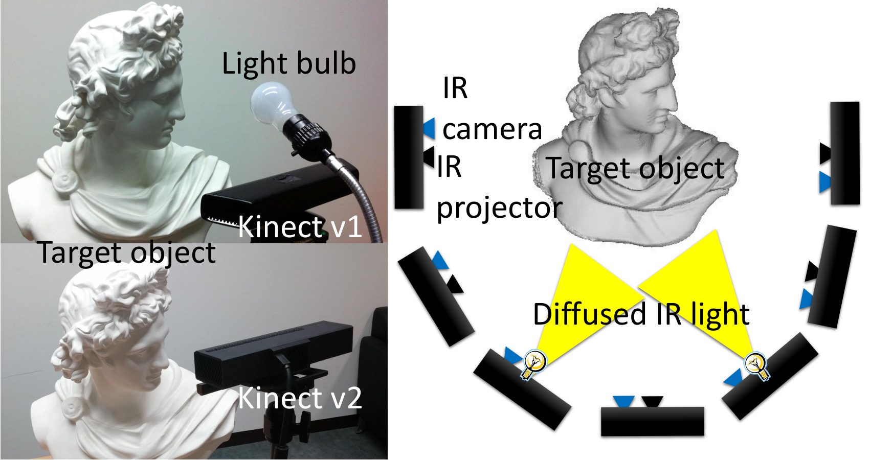
Our data capturing process is composed of two main modules, which are the initial geometry acquisition and IR shading image acquisition. Figure 11 shows our data capturing system. Using Kinect I, we obtain the initial mesh model from Kinect fusion while scanning the target object. At the same time, IR shading images are captured at several discrete viewpoints. When capturing the IR shading images, Kinect fusion is paused to update the mesh, and the Kinect IR projector is blocked so that the uniform IR light constructs our desired IR shading images. We use an additional wide spectrum point light source since we cannot switch the speckle pattern to a uniform IR light from the Kinect IR projector using the Kinect SDK. 55 5 Kinect IR projector is hard-wired and cannot be modifed Note that this process can be simplified by using a Kinect IR projector if the pattern from the Kinect IR projector is programmable. The locations where we capture shading images belong to the subset of camera poses during Kinect fusion. The camera poses are estimated using the Kinect SDK by registering Kinect depth map with the current reconstructed surface. The relative location of the additional wide spectrum point light source and the Kinect IR camera is fixed and pre-calibrated. Therefore, lighting direction, in Eq. (6), is known after data capturing.
The capturing process of Kinect II takes the same form as that of the Kinect I. However, the Kinect II emits a uniform IR light and does not require the additional light source, which makes our setup simpler. Additionally, we capture a depth and IR shading image pair at the single viewpoint for further analysis. Since the indoor ambient lights does not affect the captured IR image, both data acquisition is performed under natural indoor lighting.
5.2 Qualitative Evaluation
We compare the geometries obtained from Kinect fusion and our refined results on the real-world objects that exhibit different shading and albedo characteristics. Also, we analyze the effect of using analytic Jacobian and the difference of using multiple and single image.
 |
 |
Cicero The statue of Cicero is made of plaster and has fine geometric details on its face and hair region. The size of Cicero is . In Fig. 12, the initial mesh from Kinect fusion and enhanced mesh from our method are compared. The back of Cicero’s head exhibits very fine levels of detail that are not shown in the initial mesh at all. In our result, the fine hair details are recovered. 22 IR shading images are used here. We provided an additional comparison with RGB shading-based refinement method proposed by Han et al., [12] in Fig. 15. The color based approaches need to encode the surrounding light environment if the image is not taken using the point light source in a dark room condition. These approaches involve spherical harmonic or polynomial environment light representation. Whereas, the benefit of IR image is that it is like a darkroom photo and initial geometry can be refined even if simple near light source model is applied. As shown in Fig. 15, the refined mesh using our approach is comparable to the color based approach. We provide the 3D models that scans complete 360 degree view of Cicero in http://rcv.kaist.ac.kr/gmchoe/project/Kinect_IR/
Apollo A statue of Apollo (size of ) is also used to verify our algorithm. The IR shading image shows that Apollo has a double eyelid on its eye but it is not expressed in the mesh from Kinect fusion. Apollo also has fine details for its hairs but were not conveyed in the initial mesh. Our refinement on the initial mesh shows enhanced double eyelids and hair geometry. We used 24 IR shading images for the result.
Towel We verified that our method works well on small objects with subtle details. A towel, size of , was used for our experiment. As shown in Fig. 12, result of towel, initial mesh loses its fine, checkered pattern and shows a flat surface geometry. However, our method can effectively recover the checkered pattern in detail and the surface of our result mesh becomes rather similar to the geometry of the real object.
Flowerpot We tested our algorithm with a multi-albedo object. The target object is a plant with a pot, measuring at . We grouped the albedo as described in Sec. 4.2. As shown in Fig. 8, plant leaves and the pot have different observation in surface albedo in the IR image. We observed that the plant leaves have smooth geometry and there was less room for refining geometric details. On the other hand, the pot has a complex geometry. We apply our method on the initial mesh from Kinect fusion. In this case, our method for multi-albedo object in Sec. 4.2 is applied prior to the mesh optimization. The cross stripes on the pot are recovered by using our method. However, the region that is marked with the red box shows less reliable result. In this region, specularity exists and it does not follow the Lambertian shading model in Eq. (1).
Human face Our method shows better mesh results for human faces as well. we captured the initial geometry and IR shading images moving around the face while the subject fixed his position and facial expression. For this experiment, we use 7 IR images to refine the 3D model. We see that the refined result shows more details at the eyes, lips, and ears compared to the mesh from Kinect fusion. Two facial models are used and evaluated.
 |
 |
Ammonite Ammonite is made of plaster and is a relief sculpture with one side of the plane is carved similar to an ammonite fossil. The size of the foreground object is . The structure of an ammonite shell is planispiral with very fine stripe patterns. Since a depth difference between the adjacent patterns is less than 1mm, we see it can not be captured from Kinect fusion mesh. However the captured IR shading image shows the original shape containing the fine stripe patterns on it and our result is optimized to exactly follow the real geometry. To refine this mesh, 3 IR shading images are used.
 |
Sweater Sweater is made of wool and has repetitive twisted patterns on it. It is high and wide. The measured depth variation of the twisted pattern is . The second row of Fig. 13 shows the IR shading image, initial mesh, and our results for the sweater dataset. The geometry from Kinect fusion does not fully express the twisted pattern on the sweater. On the other hand, our result recovers the twisted pattern clearly.
 |
Effect of Analytic Jacobian As our approach applies optimization for mesh refinement, the analytic Jacobian described in Sec. 4.3 is helpful for an efficient optimization. To verify the effect, we utilize both numerical Jacobian and analytic Jacobian for the mesh optimization using Cicero dataset. The result is shown in Fig. 14. For each of the experiments, and are set to be optimal. In Fig. 14 (b, c), wrinkles of the forehead and eyes are refined well in both cases (see upper bound box). However, in the neck and the torso region of the model, the two cases show differences in terms of its quality. In Fig. 14 (b), some wave-like artifact is caused. On the other hand, Fig. 14 (d) shows better results for the refined mesh, as the wave artifact is suppressed (see lower bound box in the figure). For each cases, mean errors of our cost function is computed after the refinement. The case of using analytic Jacobian shows less error.
Number of Images As depicted in Eq. (5), IR shading images are used for giving photometric cues to each vertex. According to the number of the input IR shading images, the quality of the refined mesh shows a difference. Figure 14 compares (a) inital mesh from Kinect fusion, (c) refined mesh using a single IR shading image and (d) refined mesh using multiple (36) images. Mesh in (c) and (d) show enhanced results where detailed features such as wrinkles in the middle of the forehead and hair are reconstructed. Also, compared to the initial mesh (a), which shows an unsharp nose caused by the loop-closing error of Kinect fusion, our method greatly suppresses errors and reconstruct the original sharpness of geometry in the real world. In (c), however, there still remains some bumpy surfaces on the face and cheek area, same as the initial (a). On the other hand, multiple images refine the surface clearly in (d). Since our method tries to optimize each vertices toward satisfying the IR shading observation, usage of multiple images better solves the shading-geometry ambiguity. We can see a more smooth surface when using multiple shading images.
5.3 Quantitative Evaluation
To verify that the rendered intensities from refined geometry follows IR shading image better, error measures of initial and our mesh in the image domain is conducted. Both initial and refined mesh are rendered in image domain based on the Eq. (1). We also generate first order gradient of rendered image to evaluate how the geometric edges follows the edge in the IR image. We use root mean square error (RMSE) which is equivalent to error between input image and rendered images. RMSE:= , where is pixel number, is input shading image and is the rendered image. To make the evaluation not biased to specific image, we conduct experiment as follows. 1) Among a set of input images, one random image is intentionally omitted. 2) Perform mesh refinement using the non-omitted images. 3) Render an image with novel viewpoint that are equivalent to the viewpoint of the omitted image. 4) Compute RMSE between rendered image and omitted image. In this way, we plotted the bar chart in Fig. 17. According to the bar chart, the error is decreased.
We also compute metric error of the initial geometry and our refined geometry. The ground truth model is obtained from a structured-light based 3D scanner. Using the Iterative Closest Point (ICP) algorithm in [2], the meshes are registered to ground truth. Then we compute metric error, which is visualized in Fig. 14 and Fig. 16.
User Study Work in [36] proposes the visual turing test via user study to evaluate the visual quality of their result. To evaluate the realism of our enhanced 3D mesh model, we conducted a series of user studies. We collected 21 subjects who are not experts of 3D computer vision. For every real-world dataset which we deal with in this paper, the subjects are asked which mesh model between the Kinect fusion and ours is more similar-looking to input IR shading image. The red bar charts in Fig. 17, (l) show the possibility that our mesh to be responded as a better quality than that of Kinect fusion. The by-chance possibility is for every dataset, which is expressed with blue bars. We see most of the people responded our results are better.
5.4 Failure Case
Although we show that our method can refine single depth-IR image of the Cicero dataset, we found that the single image input does not fully guarantee the success of refinement due to shading-geometry ambiguity. In Fig. 18, a result comparison between an initial geometry and refined geometry for an ornamental stone dataset is shown. The ornamental stone dataset has fine details and it is not represented in the initial geometry. A result from our method (See Fig. 18 (c)) shows better quality of geometry, whose geometric details follow the input IR shading image. However, when we look at the geometry at different viewpoints, the geometry shows a bumpy surface and less accurate result. We let this problem as a future work.

6 Discussion
As a limitation of our work, we assume the Lambertian BRDF which makes our results error-prone to specular highlight. Due to the usage of Kinect fusion algorithm, we also assume the reconstructed object is static. In future, we will study how to extend our work to handle non-Lambertian BRDF objects, and geometry refinement for dynamic object reconstructions. The depth based camera tracking is not perfect due to accumulation error of estimated camera poses. Such problem results in unpleasant geometric seams as shown in Fig. 14 (a). Our algorithm does not target bundle adjustment of camera poses. However, if the amount of tracking error is not severe, our approach can refine geometry to minimize multi-view shading inconsistencies. As shown in Fig. 14 (d), the refined mesh shows relieved geometric seams and geometric details. We believe this result supports that our approach correctly minimizes the gap between initial geometry and observed shading image even in presence of camera tracking error. For the every results displayed in the paper, we did not process camera poses before mesh refinement. However, if the tracking error is not ignorable, the projection matrices or image coordinate can be further optimized so that the depth and shading images more precisely be aligned as introduced in [48, 49]. About the radiometric calibration, in Chatterjee et al.[5], they utilize two auxiliary light sources and finds out linearity of the response function. However, according to our repeated experiment, the gamma curve does not fitted to 1 which indicates linear response. We could not exactly reproduce the approach as the paper does not describe which Kinect device is used and how the IR images are grabbed (we utilized Microsoft Kinect SDK 1.7 for Kinect I and 2.0 for Kinect II). However, we agree that shape of response function is near to linear as we seen inFig. 5 (b),(c). Here, we choose gamma function as a camera response function because the gamma curve expresses most of the observed intensities fairly well. However, this also opens interesting research direction since the radiometric calibration on the IR cameras is rarely studied compared to the color cameras. About the multiple albedo, our method is built upon simple image formation model assuming constant albedo and Lambertian shading on the scene. Although our extension to care multiple albedo have been demonstrated on the several real-world examples, there is a room for improving our approach to handle complex cases such as non-Lambertian objects exhibiting sub-space scattering, non-constant albedo, or strong specular. Moreover, an effective specular handling mehod should be further studied for enhancing the mesh quality of reflexible objects. Also, as we analyzed in Fig. 18, we will try to reinforce our method to more robustly handle the single image refinement.
7 Conclusion
In this paper, we have presented a framework to utilize shading information from Kinect IR images for geometry refinement. This work studies the shading information inherent in the Kinect IR images and utilizes them for geometry refinement. As demonstrated in our study, the captured spectrum of Kinect IR images does not have any overlapping with visible spectrum which makes our acquisition unaffected by indoor illumination condition. Since there is almost no ambient light in IR spectrum, the captured intensity can be accurately modeled by our near light IR shading model assuming the captured materials follow the Lambertian BRDF.
We have also described a method to radiometrically calibrate the Kinect IR image using a diffuse sphere, a method to estimate albedo and do albedo grouping, and a new mesh optimization method to refine geometry by estimating a displacement vector along vertex normal direction. Our experimental results show that our framework is effective and demonstrates high-quality mesh model via our geometry refinements. Major experiments are done using multiple IR shading images at different viewpoints. The effectiveness of our method is demonstrated via various real-world examples using both Kinect I and Kinect II.
References
- (1) Bellia, L., Bisegna, F., Spada, G.: Lighting in indoor environments: Visual and non-visual effects of light sources with different spectral power distributions. Building and Environment 46(10), 1984 – 1992 (2011)
- (2) Besl, P., McKay, N.D.: A method for registration of 3-d shapes. IEEE Trans. on Pattern Analysis and Machine Intelligence (TPAMI) 14(2), 239–256 (1992)
- (3) Bohme, M., Haker, M., Martinetz, T., Barth, E.: Shading constraint improves accuracy of time-of-flight measurements. Computer Vision and Image Understanding (CVIU) 114(12), 1329 – 1335 (2010)
- (4) Boykov, Y., Kolmogorov, V.: An experimental comparison of min-cut/max-flow algorithms for energy minimization in vision. IEEE Trans. on Pattern Analysis and Machine Intelligence (TPAMI) 26(9), 1124–1137 (2004)
- (5) Chatterjee, A., Madhav Govindu, V.: Photometric refinement of depth maps for multi-albedo objects. In: Proc. of Computer Vision and Pattern Recognition (CVPR), pp. 933–941 (2015)
- (6) Choe, G., Park, J., Tai, Y.W., Kweon, I.S.: Exploiting shading cues in kinect ir images for geometry refinement. In: Proc. of Computer Vision and Pattern Recognition (CVPR) (2014)
- (7) Delaunoy, A., Pollefeys, M.: Photometric bundle adjustment for dense multi-view 3d modeling. In: Proc. of Computer Vision and Pattern Recognition (CVPR) (2014)
- (8) Dolson, J., Baek, J., Plagemann, C., Thrun, S.: Upsampling range data in dynamic environments. In: Proc. of Computer Vision and Pattern Recognition (CVPR) (2010)
- (9) Fanello, S.R., Keskin, C., Izadi, S., Kohli, P., Kim, D., Sweeney, D., Criminisi, A., Shotton, J., Kang, S.B., Paek, T.: Learning to be a depth camera for close-range human capture and interaction 33(4), 86:1–86:11 (2014)
- (10) Fischler, M.A., Bolles, R.C.: Random sample consensus: a paradigm for model fitting with applications to image analysis and automated cartography. Communications of the ACM 24(6), 381–395 (1981)
- (11) Grossberg, M., Nayar, S.: Modeling the space of camera response functions. IEEE Trans. on Pattern Analysis and Machine Intelligence (TPAMI) 26(10), 1272–1282 (2004)
- (12) Han, Y., Lee, J.Y., Kweon, I.S.: High quality shape from a single rgb-d image under uncalibrated natural illumination. In: Proc. of Int’l Conf. on Computer Vision (ICCV) (2013)
- (13) Haque, S., Chatterjee, A., Govindu, V.: High quality photometric reconstruction using a depth camera. In: Proc. of Computer Vision and Pattern Recognition (CVPR) (2014)
- (14) Hernandez, C., Vogiatzis, G., Cipolla, R.: Multiview photometric stereo. IEEE Trans. on Pattern Analysis and Machine Intelligence (TPAMI) 30(3), 548–554 (2008)
- (15) Higo, T., Matsushita, Y., Joshi, N., Ikeuchi, K.: A hand-held photometric stereo camera for 3-d modeling. In: Proc. of Int’l Conf. on Computer Vision (ICCV), pp. 1234–1241. IEEE (2009)
- (16) Horn, B.K.P., Brooks, M.J.: Shape from shading. MIT Press, Cambridge, MA, USA (1989)
- (17) Horn, B.K.P., J., R.: Determining shape and reflectance using multiple images. In: MIT AI Memo (1978)
- (18) Ikeuchi, K., Horn, B.K.: Numerical shape from shading and occluding boundaries. Artificial Intelligence 17(1–3), 141 – 184 (1981)
- (19) Izadi, S., Kim, D., Hilliges, O., Molyneaux, D., Newcombe, R., Kohli, P., Shotton, J., Hodges, S., Freeman, D., Davison, A., Fitzgibbon, A.: Kinectfusion: Real-time 3d reconstruction and interaction using a moving depth camera. In: Proceedings of the 24th Annual ACM Symposium on User Interface Software and Technology (2011)
- (20) Kanungo, T., Mount, D., Netanyahu, N., Piatko, C., Silverman, R., Wu, A.: An efficient k-means clustering algorithm: Analysis and implementation. IEEE Trans. on Pattern Analysis and Machine Intelligence (TPAMI) 24(7), 881–892 (2002)
- (21) Kerl, C., Sturm, J., Cremers, D.: Dense visual slam for rgb-d cameras. In: Proc. of Int’l Conf. on Intelligent Robots and Systems (IROS) (2013)
- (22) Kopf, J., Cohen, M.F., Lischinski, D., Uyttendaele, M.: Joint bilateral upsampling. ACM Trans. on Graph.(TOG) 26(3), 96 (2007)
- (23) Lensch, H., Kautz, J., Goesele, M., Heidrich, W., Seidel, H.P.: Image-based reconstruction of spatial appearance and geometric detail. ACM Trans. on Graph.(TOG) 22(2), 234–257 (2003)
- (24) Leyvand, T., Meekhof, C., Wei, Y., Sun, J., Guo, B.: Kinect identity: Technology and experience. IEEE Computer 44(4), 94–96 (2011)
- (25) Liao, M., Wang, L., Yang, R., Gong, M.: Light fall-off stereo. In: Proc. of Computer Vision and Pattern Recognition (CVPR), pp. 1–8. IEEE (2007)
- (26) Longuet-Higgins, H.C.: A computer algorithm for reconstructing a scene from two projections. Nature 193, 133 – 135 (1981)
- (27) Lu, Z., Tai, Y.W., Ben-Ezra, M., Brown, M.S.: A framework for ultra high resolution 3d imaging. In: Proc. of Computer Vision and Pattern Recognition (CVPR) (2010)
- (28) Nehab, D., Rusinkiewicz, S., Davis, J., Ramamoorthi, R.: Efficiently combining positions and normals for precise 3d geometry. ACM Trans. on Graph.(TOG) 24(3), 536–543 (2005)
- (29) Okatani, T., Deguchi, K.: Optimal integration of photometric and geometric surface measurements using inaccurate reflectance/illumination knowledge. In: Proc. of Computer Vision and Pattern Recognition (CVPR) (2012)
- (30) Or-El, R., Rosman, G., Wetzler, A., Kimmel, R., Bruckstein, A.M.: Rgbd-fusion: Real-time high precision depth recovery. In: Proc. of Computer Vision and Pattern Recognition (CVPR), pp. 5407–5416 (2015)
- (31) Park, J., Kim, H., Tai, Y.W., Brown, M.S., Kweon, I.S.: High quality depth map upsampling for 3d-tof cameras. In: Proc. of Int’l Conf. on Computer Vision (ICCV) (2011)
- (32) Park, J., Kim, H., Tai, Y.W., Brown, M.S., Kweon, I.S.: High quality depth map upsampling and completion for rgb-d cameras. IEEE Trans. on Image Processing (TIP) (2014)
- (33) Park, J., Sinha, S.N., Matsushita, Y., Tai, Y.W., Kweon, I.S.: Multiview photometric stereo using planar mesh parameterization. In: Proc. of Int’l Conf. on Computer Vision (ICCV) (2013)
- (34) Salamati, N., Fredembach, C., Süsstrunk, S.: Material classification using color and nir images. In: Proc. of IS&T/SID 17th Color Imaging Conference (CIC) (2009)
- (35) Seitz, S.M., Curless, B., Diebel, J., Scharstein, D., Szeliski, R.: A comparison and evaluation of multi-view stereo reconstruction algorithms. In: Proc. of Computer Vision and Pattern Recognition (CVPR) (2006)
- (36) Shan, Q., Adams, R., Curless, B., Furukawa, Y., Seitz, S.M.: The visual turing test for scene reconstruction. In: Proc. of Int’l Conf. on 3D Vision (3DV) (2013)
- (37) Shen, J., Cheung, S.C.S.: Layer depth denoising and completion for structured-light rgb-d cameras. In: Proc. of Computer Vision and Pattern Recognition (CVPR) (2013)
- (38) Shi, B., Inose, K., Matsushita, Y., Tan, P., Yeung, S.K., Ikeuchi, K.: Photometric stereo using internet images. In: Proc. of Int’l Conf. on 3D Vision (3DV) (2014)
- (39) Shotton, J., Fitzgibbon, A., Cook, M., Sharp, T., Finocchio, M., Moore, R., Kipman, A., Blake, A.: Real-time human pose recognition in parts from a single depth image. In: Proc. of Computer Vision and Pattern Recognition (CVPR) (2011)
- (40) Surazhsky, V., Gotsman, C.: Explicit surface remeshing. In: Proceedings of the 2003 Eurographics/ACM SIGGRAPH symposium on Geometry processing
- (41) Suwajanakorn, S., Kemelmacher-Shlizerman, I., Seitz, S.M.: Total moving face reconstruction. In: Proc. of European Conf. on Computer Vision (ECCV) (2014)
- (42) Vlasic, D., Peers, P., Baran, I., Debevec, P., Popović, J., Rusinkiewicz, S., Matusik, W.: Dynamic shape capture using multi-view photometric stereo. ACM Trans. on Graph.(TOG) 28(5) (2009)
- (43) Wu, C., Wilburn, B., Matsushita, Y., Theobalt, C.: High-quality shape from multi-view stereo and shading under general illumination. In: Proc. of Computer Vision and Pattern Recognition (CVPR) (2011)
- (44) Wu, C., Zollhöfer, M., Niessner, M., Stamminger, M., Izadi, S., Theobalt, C.: Real-time shading-based refinement for consumer depth cameras. In: Proc. SIGGRAPH Asia (2014)
- (45) Yang, Q., Yang, R., Davis, J., Nistér, D.: Spatial-depth super resolution for range images. In: Proc. of Computer Vision and Pattern Recognition (CVPR) (2007)
- (46) Yu, L.F., Yeung, S.K., Tai, Y.W., Lin, S.: Shading-based shape refinement of rgb-d images. In: Proc. of Computer Vision and Pattern Recognition (CVPR) (2013)
- (47) Zhang, Q., Ye, M., Yang, R., Matsushita, Y., Wilburn, B., Yu, H.: Edge-preserving photometric stereo via depth fusion. In: Proc. of Computer Vision and Pattern Recognition (CVPR) (2012)
- (48) Zhou, Q.Y., Koltun, V.: Color map optimization for 3d reconstruction with consumer depth cameras. ACM Transactions on Graphics (TOG) 33(4), 155 (2014)
- (49) Zollhöfer, M., Dai, A., Innmann, M., Wu, C., Stamminger, M., Theobalt, C., Nießner, M.: Shading-based refinement on volumetric signed distance functions