Cyclical Multiple Access in UAV-Aided Communications: A Throughput-Delay Tradeoff
Abstract
This letter studies a wireless system consisting of distributed ground terminals (GTs) communicating with an unmanned aerial vehicle (UAV) that serves as a mobile base station (BS). The UAV flies cyclically above the GTs at a fixed altitude, which results in a cyclical pattern of the strength of the UAV-GT channels. To exploit such periodic channel variations, we propose a new cyclical multiple access (CMA) scheme to schedule the communications between the UAV and GTs in a cyclical time-division manner based on the flying UAV’s position. The time allocations to different GTs are optimized to maximize their minimum throughput. It is revealed that there is a fundamental tradeoff between throughput and access delay in the proposed CMA. Simulation results show significant throughput gains over the case of a static UAV BS in delay-tolerant applications.
Index Terms:
Unmanned aerial vehicles, mobile base station, periodic channel, cyclical multiple access, throughput-delay tradeoffI Introduction
With their high mobility and reducing cost, unmanned aerial vehicles (UAVs) have found applications in wireless communication systems [1], either to support the existing cellular networks in high-demand and overloaded situations [2], or to provide wireless connectivity in areas without infrastructure coverage such as battle fields or disaster scenes [3]. Compared to terrestrial communications, UAV-aided wireless systems are in general faster to deploy, more flexibly reconfigured, and likely to have better communication channels due to line-of-sight links. For example, the UAV can be deployed as a quasi-stationary aerial base station (BS) for the ground terminals (GTs) [4, 5]. Thanks to high mobility, UAVs can also be deployed as mobile relays to provide wireless connectivity between distant GTs whose direct links are severely blocked [6, 7]. The deployment of UAVs is also considered in [8] to improve connectivity of wireless ad-hoc networks.
In this letter, we consider a wireless system with the UAV deployed as a mobile BS to provide wireless connectivity for a group of distributed GTs. Compared to static UAV BSs in [4, 5], the UAV controlled mobility is exploited to improve channel quality and thus system throughput. We assume that the UAV flies cyclically above the GTs at a fixed altitude, which results in cyclically varying patterns of the strength of the UAV-GT channels. We thus propose a new cyclical multiple access (CMA) scheme where GTs are scheduled to communicate with the UAV in a cyclical time-division manner to exploit the good channel when the UAV flies closer to each of them. We propose an algorithm to allocate the time to different GTs based on the flying UAV’s position to maximize their minimum throughput. We also analyze the access delay patterns of the GTs due to CMA and reveal a fundamental trade-off between throughput and delay. Numerical results show that the max-min throughput is significantly improved by the proposed CMA with a mobile UAV BS over the case of a static BS, at the expense of increased access delay. Thus, the proposed UAV-assisted mobile BS with CMA is most suitable in delay-tolerant applications [9] such as periodic sensing, large data transfer, etc. The mobile UAV BS case is also considered in [10] to optimize the coverage performance.
II System Model
We consider a wireless communication system where a UAV is employed as a mobile BS to communicate with GTs. We assume that the GTs are equally spaced on the ground along a straight line with the length of meters, as shown in Fig. 1. Thus, the location of the th GT can be expressed as , . Note that the assumption of one-dimensional (1D) uniform GT locations is for the purpose of exposition to draw essential insights to the performance and design of the new UAV-assisted communication system. The results can be extended to arbitrary GT locations in general 2D or 3D setups, which are left for our future work. In practice, each GT in the considered 1D model could correspond to a cluster head that serves as a gateway for a cluster of nearby nodes communicating with the UAV. When the nodes are densely populated and the number of clusters is large, the cluster heads can be approximated to be equally spaced.

We assume that the UAV flies horizontally above the GTs following a cyclical trajectory with period , i.e., the UAV position repeats every seconds. For simplicity, we assume that the UAV flies at a fixed altitude , which could correspond to the minimum value required for safety considerations (e.g., terrain or building avoidance). The extension to variable will be left as future work. For the symmetric 1D GT distribution considered in this letter, it is intuitive that the UAV’s trajectory , should be symmetric over the origin. Thus, assuming the UAV flies with a constant speed , we have , , with the trajectory length , as shown in Fig. 1.
We consider the downlink communications where the UAV sends independent messages to the GTs over a given frequency band, whereas the obtained results can be similarly applied to uplink communications. We assume the communication channels are dominated by line-of-sight (LoS) links, and the Doppler effect due to the UAV’s mobility is assumed to be perfectly compensated. Though simplified, the LoS model offers a good approximation for the UAV-GT channels in practice, which suffices for us to characterize the fundamental performance tradeoff. Therefore, at time instant , the channel power gain from the UAV to each GT follows the free-space path loss model given by
| (1) |
where denotes the channel power gain at the reference distance meter (m), whose value depends on the carrier frequency, antenna gain, etc., and is the link distance between the UAV and the -th GT at time . Note that from (1), it follows that for each GT with fixed location , its channel with the moving UAV with position varies in a periodic manner over , which is perfectly known at the UAV. By assuming a constant transmission power by the UAV, the instantaneous channel capacity from the UAV to the -th GT in bits/second/Hz (bps/Hz) can be expressed as
| (2) |
where denotes the noise power at each GT receiver. In the following, we use the unit of bps/Hz to measure the throughput per unit bandwidth, also known as the spectrum efficiency.
III Cyclical Multiple Access
To exploit periodic channel variations of different GTs, we propose a new multiple access scheme called CMA where GTs communicate with the UAV in a cyclical time-division manner, for which the details are given in this section.
III-A Cyclical TDMA
From (1) and (2), the maximum achievable rate of GT as a function of the UAV horizontal position is given by
| (3) |
where represents the reference signal-to-noise ratio (SNR). From (3), it follows that for each GT , the rate is symmetric and unimodal, which achieves its maximum at . Moreover, the rate expressions of different GTs are identical except that they have different shifts along the x-coordinate according to different GT locations ’s . As an illustration, Fig. 2(a) plots the instantaneous rate of each GT versus the UAV position , with , dBm, dB, m, and m.
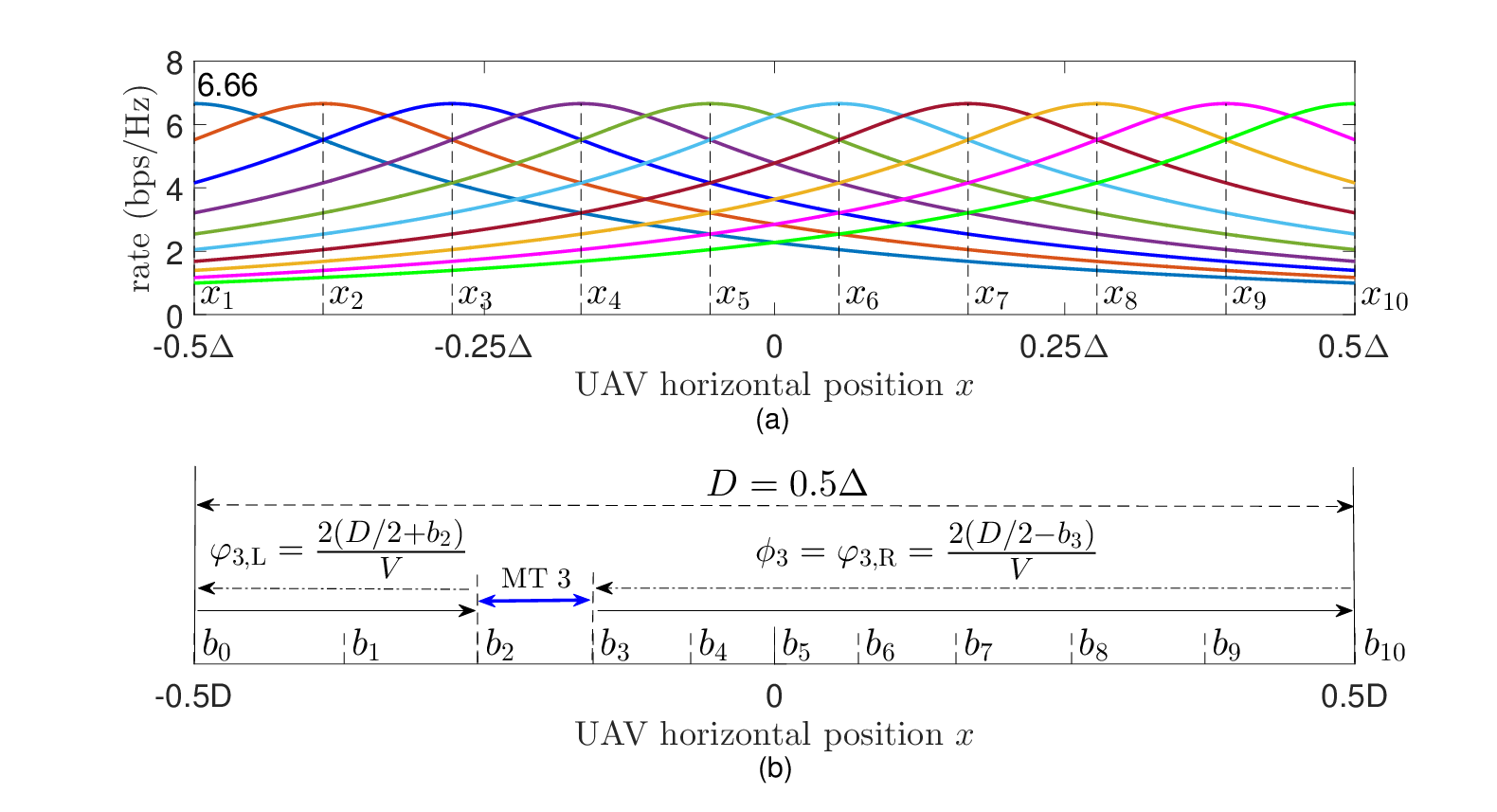
Since each GT has its highest rate when , it is intuitive to allocate the segment of the UAV trajectory near to GT for communication, so as to maximize the throughput to all GTs. Motivated by this, we propose a simple time-division based CMA, termed cyclical TDMA, to schedule the communications from the UAV to different GTs based on the UAV position. Specifically, the one-way UAV trajectory of length is divided into contiguous horizontal segments: , which are allocated to the GTs for orthogonal transmissions, respectively. For convenience, let and . Then the UAV trajectory segment and its corresponding time interval is allocated to GT . With such a periodic TDMA scheme, the average throughput of GT in bps/Hz is obtained as
| (4) |
where we have used the identity and . The integral of the rate function can be obtained in closed-form as
| (5) |
Therefore, the throughput of GT is given by
| (6) |
III-B Max-Min Throughput
For a fixed UAV trajectory length , we study the problem of maximizing the minimum throughput among all GTs, denoted by , by optimizing the delimiting variables for their time allocations. The max-min throughput is used to maximize the overall throughput while ensuring fairness among all GTs. The problem can be formulated as
where is a non-concave function of and from (5) and (6). Therefore, (P1) is non-convex and thus cannot be directly solved via standard convex optimization techniques.
Fortunately, (P1) can be efficiently solved by exploiting the following two properties. Firstly, it can be proved that all GTs have equal throughput when the max-min throughput is achieved. Secondly, note that if all other delimiting variables are fixed, the optimization variable only affects the throughputs of GT and GT . The first property can be proved by contradiction. Assume that the max-min throughput is achieved at a single GT while its neighboring GT (or if ) has a higher throughput, i.e.,
| (7) |
As increases from to , monotonically increases from while monotonically decreases to . Therefore, there exists a unique value of which makes
| (8) |
This contradicts with the assumption that is the max-min throughput, since it can be increased to . The cases in which the max-min throughput is achieved at multiple GTs can be proved in a similar way.
The above proof also suggests a method to obtain the max-min throughput . Based on the above two properties, we can fix and optimize to ensure that , i.e., can be updated by solving for from the following equation:
| (9) |
We therefore propose Algorithm 1 to iteratively tune the delimiting variables to achieve the max-min throughput for (P1). In each iteration, we pick the delimiting variable that corresponds to the largest throughput gap between two neighboring GTs and . Then we tune to eliminate this gap by solving equation (9). The iterations repeat until all the throughput gaps between two neighboring GTs are smaller than a certain threshold .
Input: GT locations ; UAV altitude , trajectory length ; transmit power , reference SNR .
Output: Trajectory delimiting variables ; max-min throughput .
Initialization: , , , ; .
Algorithm 1 achieves the max-min throughput for any fixed trajectory length , which can be proved by contradiction. First of all, Algorithm 1 is guaranteed to converge since the largest throughput gap is bounded below by 0 and is decreasing in each iteration. After convergence, Algorithm 1 returns the delimiting variables which yields and thus all GTs have equal throughputs given by
| (10) |
where denotes the achievable max-min throughput. Now assume there exists a higher max-min throughput , with the delimiting variables . Then we have
| (11) |
Since the integral function is monotonically increasing, from (11) we have . By induction, we can similarly conclude that . However, this contradicts with the assumption that , which also results in from the following inequality:
| (12) |
Therefore, achieved by Algorithm 1 is indeed the max-min throughput. The proof is thus completed.
For the example in Fig. 2(a) with , assume that the one-way trajectory length is set to . Denote the portion of the UAV trajectory allocated to GT as , i.e.,
| (13) |
Algorithm 1 is applied to obtain the optimal delimiting variables shown in Fig. 2(b), which achieve the max-min throughput bps/Hz. Note that the allocated trajectory portions are non-uniform for different GTs. In general, the middle GTs require a smaller portion of the trajectory to achieve the same throughput since they enjoy better channels than the GTs on the two sides.
For benchmark comparison with a static UAV BS, since all GTs are symmetric around the origin, the optimal fixed UAV position for max-min throughput is due to symmetry. Since the UAV-GT channels are fixed, by optimizing the time allocation, the max-min throughput in the static UAV case can be obtained as
| (14) |
which has a value of 0.3488 bps/Hz for the example in Fig. 2(a). The static UAV BS scenario can be treated as an extreme case of the proposed cyclical TDMA with zero UAV trajectory length, i.e., . It is found that the max-min throughput achieved by the mobile UAV BS with is 33.7% higher than that of the static UAV BS case. This gain is owing to the UAV mobility, which can be further improved by optimizing the trajectory length (as will be shown later in Section IV). However, for a fixed UAV speed , the trajectory period and hence the access delay of the GT communications increases with . Therefore, there exists a general tradeoff between maximizing the throughput and minimizing the access delay, in selecting the value of in the proposed mobile UAV BS with CMA.
III-C Access Delay
Within each period of the UAV cyclical trajectory from to and then back to , each GT can communicate with the UAV in two non-consecutive time windows corresponding to the UAV position . This results in two non-consecutive “mute” time windows in which GT cannot communicate with the UAV whose lengths are denoted as and , corresponding to the UAV trajectory on the left and right sides, respectively. For the example with 10 GTs, the UAV trajectory segment is allocated to GT 3, with and also shown in Fig. 2(b).
Define the access delay as the longest contiguous mute time of GT in a UAV flying period , i.e.,
| (15) |
According to this definition, the GTs have different access delays depending on their relative locations along the UAV trajectory. In general, the middle GTs have smaller access delays since and are roughly the same, while the GTs on the two sides have larger access delays since and are unbalanced. Such access delay patterns need to be considered when designing upper-layer protocols or applications with different delay requirements.
Note that the access delay depends on the flying speed , UAV trajectory length , as well as the delimiting variables , which need to be obtained using Algorithm 1. There could be various ways to characterize the overall access delay of all GTs. In this letter, we adopt the root-mean-square (RMS) access delay defined as
| (16) |
which accounts for both the average value and variations of the delay. In general, monotonically increases with , since the round-trip period is proportional to with fixed . In this letter, we assume the system requires an RMS access delay no larger than , i.e., .
Note that the access delay considered in this letter is different from the conventional communication delay. Access delay is caused by the cyclical TDMA in which the GTs take turns to access the channel when the UAV flies above them. In the limiting case with a static UAV BS (or equivalently, in the mobile UAV BS case), the access delay can be arbitrarily small since the time frame can be divided into arbitrarily small mini-slots, each assigned to one GT for communication. However, this is not the case in cyclical TDMA with non-zero trajectory length , since given a finite value of UAV speed , each GT may need to wait a maximum time equal to its access delay given in (15) for any two adjacent communications with the UAV (which in practice can be significantly larger than the conventional delay due to packet transmission).
IV Numerical Results
In this section, we normalize the trajectory length to the GT location range for convenience, denoted as . The following parameters are used: dBm, dB, m, and m/s. For the same example in Fig. 2(a) with GTs, we compare the max-min throughput under different RMS access delay tolerance values to show the fundamental throughput-delay trade-off. For each pair of their values shown in Fig. 3, the corresponding optimal is obtained by searching subject to that the resulted RMS access delay is no larger than the given tolerance value , as follows. First, based on Algorithm 1, we obtain the max-min throughput among all GTs for a fixed value of . Then, we find the optimal such that the resulted RMS delay satisfies the given (i.e., ) to maximize . This can be done by a simple one-dimensional search as the RMS access delay in general monotonically increases with . Besides the optimal time/segment allocation proposed in Algorithm 1, we also consider a simple equal time allocation scheme for comparison, which corresponds to , with similarly defined as in (13).
First, it is observed that for the case of m, the two schemes with optimal and equal time allocations achieve their peak values bps/Hz and 0.6523 bps/Hz at and 1.11, respectively, and the corresponding RMS delays are s and 52.85s, respectively. Therefore, if sufficiently large access delay can be tolerated, e.g., s, the simple equal time allocation with the optimal trajectory length achieves the near-optimal performance. On the other hand, for relatively stringent access delay requirement, e.g., s, the cyclical TDMA with the optimal time allocation by Algorithm 1 significantly outperforms that with the equal time allocation.
Next, we investigate the throughput gain of the mobile UAV BS over its static UAV BS special case (), both with optimal time allocations. We have shown in Section III-B that for fixed trajectory length , a throughput gain of 33.7% is achievable by the mobile UAV BS, whereas the gain further increases to 87% with optimized as shown in Fig. 3, at the cost of increased access delay. This gain is further increased in the case of a larger GT location range , i.e., up to 236% when m as shown in Fig. 3. The rationale is that when increases, the GTs on the two sides experience even poorer channels in the static UAV BS case, which degrades the max-min throughput significantly. On the contrary, cyclical TDMA still maintains a high max-min throughput, since all GTs can enjoy good channels in their allocated UAV trajectory segments, if the trajectory length is optimized with respect to the location range accordingly.

V Conclusions
This letter proposed a new cyclical multiple access scheme in UAV-aided wireless communications, and characterized the max-min throughput by optimally allocating the transmission time to GTs based on the UAV position. Simulation results showed significant throughput gains with the proposed design over the static UAV BS case in delay-tolerant scenarios. Possible extensions of this letter for future work may include the general GT locations in 2D or 3D setups, variable speed/altitude control of the UAV, deployment and cooperation of multiple UAVs, etc.
References
- [1] Y. Zeng, R. Zhang, and T. J. Lim, “Wireless communications with unmanned aerial vehicles: opportunities and challenges,” IEEE Commun. Mag., vol. 54, no. 5, pp. 36–42, May 2016.
- [2] S. Rohde and C. Wietfeld, “Interference aware positioning of aerial relays for cell overload and outage compensation,” in Proc. IEEE Vehicular Technology Conference (VTC), Sept. 2012, pp. 1–5.
- [3] A. Merwaday and I. Guvenc, “UAV assisted heterogeneous networks for public safety communications,” in Proc. IEEE Wireless Commun. Netw. Conf., Mar. 2015, pp. 329–334.
- [4] A. Al-Hourani, S. Kandeepan, and S. Lardner, “Optimal LAP altitude for maximum coverage,” IEEE Wireless Commun. Lett., vol. 3, no. 6, pp. 569–572, Dec. 2014.
- [5] M. Mozaffari, W. Saad, M. Bennis, and M. Debbah, “Drone small cells in the clouds: design, deployment and performance analysis,” in Proc. IEEE GLOBECOM, Dec. 2015, pp. 1–6.
- [6] P. Zhan, K. Yu, and A. L. Swindlehurst, “Wireless relay communications with unmanned aerial vehicles: performance and optimization,” IEEE Trans. Aerosp. Electron. Syst., vol. 47, no. 3, pp. 2068–2085, July 2011.
- [7] Y. Zeng, R. Zhang, and T. J. Lim, “Throughput maximization for mobile relaying systems,” submitted to IEEE Trans. Commun., 2016, (available online at arxiv/1604.02517).
- [8] Z. Han, A. L. Swindlehurst, and K. J. R. Liu, “Optimization of manet connectivity via smart deployment/movement of unmanned air vehicles,” IEEE Trans. Veh. Technol., vol. 58, no. 7, pp. 3533–3546, Sept. 2009.
- [9] M. J. Khabbaz, C. M. Assi, and W. F. Fawaz, “Disruption-tolerant networking: a comprehensive survey on recent developments and persisting challenges,” IEEE Commun. Surv. Tut., vol. 14, no. 2, pp. 607–640, 2012.
- [10] M. Mozaffari, W. Saad, M. Bennis, and M. Debbah, “Unmanned aerial vehicle with underlaid device-to-device communications: Performance and tradeoffs,” IEEE Trans. on Wireless Commun., vol. 15, no. 6, pp. 3949–3963, June 2016.