Asymmetric Pt/Co/Pt structure as a platform for extracting pure spin Hall torque
Abstract
We have quantitatively studied the spin-orbit torque purely generated by the spin Hall effect in a wide range of temperatures by intensionally eliminating the Rashba spin-orbit torque using Pt/Co/Pt trilayers with asymmetric thicknesses of the top and bottom Pt layers. The vanishingly small contribution from the Rashba effect has been confirmed through the vector measurements of the current-induced effective fields. In order to precisely determine the value of the spin Hall torque, the complete cancelation of the spin Hall torque has been verified by fabricating symmetric Pt/Co/Pt structure on SiO2 and Gd3Ga5O12 (GGG) substrates. Despite of the complete cancelation on the GGG substrate, the spin Hall torque cannot be completely canceled out even when the top and bottom Pt layers have same thicknesses on the SiO2 substrate, which suggests that Pt/Co/Pt trilayers on a GGG substrate is a suitable system for precise measurements of the spin Hall torque. The result of the vector measurements on Pt/Co/Pt/GGG from 300 to 10 K shows that the spin Hall torque is almost independent of temperature, which is quantitatively reproduced under the assumption of the temperature-independent spin Hall angle of Pt.
I I. introduction
Magnetization switching manipulated by current in nano-scale films is promising for the future spintronic-based memory and logic devices due to its low energy consumption and high-speed response, which has attracted robust research interests in recent years [1, 2, 3, 4, 5, 6, 7, 8, 9, 10, 11, 12, 13, 14]. Typically, in oxide/ferromagnetic metal (FM)/non-magnetic heavy metal (NM) trilayers with perpendicular magnetic anisotropy, by injecting in-plane current into the NM layer with strong spin-orbit coupling, spin-orbit torque (SOT) is generated through the Rashba effect and spin Hall effect (SHE), then transferred into the FM layer, leading to the efficient switching of the magnetization orientation in the FM layer [15, 16, 17, 18, 19, 20, 21, 22, 23, 24]. In the above oxide/FM/NM material systems, two types of SOTs are responsible for the magnetization switching, the damping-like (Slonczewski) torque with the form of and the field-like torque with the form of , where and are unit vectors of the magnetization in the FM layer and nonequilibrium spin polarization direction in the NM layer, respectively [18, 25]. Equivalently, the two kinds of torques yield to a damping-like effective field and a field-like effective field , respectively. The damping-like torque, which counteracts magnetization damping, can switch the magnetization directly and the field-like torque can lower the energy barrier for switching [26]. In the oxide/FM/NM trilayers, due to the structural inversion asymmetry, the Rashba effect and the SHE coexists. Both the Rashba and spin Hall effects can generate field-like () and damping-like () torques. Although this may benefit the magnetization switching, it is difficult to precisely separate and quantitatively investigate the spin-orbit physics in metallic heterostructures.
In this paper, we fabricate Pt/Co/Pt trilayers with asymmetric thicknesses of the top and bottom Pt layers [see Fig. 1(a)] to study the SOT purely generated by the SHE in a large range of temperatures. Since the Rashba SOTs, which can be induced at the top Pt/Co and bottom Co/Pt interfaces, are cancelled out due to the opposite signs of the Rashba SOTs generated at the two interfaces [27, 28, 29, 30], the asymmetric Pt/Co/Pt structure allows us to quantitatively study the SOT purely generated by the SHE. In the case of symmetric thicknesses of the top and bottom Pt layers, the charge current density in both Pt layers will be same, leading to the complete elimination of the SOT due to the SHE. The charge current density is still same in both Pt layers even by setting different thicknesses of both Pt layers. However, the spin current density injected into the Co layer from both Pt layers will be asymmetric due to the effect of spin diffusion and relaxation as shown in Fig. 1(b). Figure 1(b) shows the spatial distribution of the spin current density in the symmetric and asymmetric Pt/Co/Pt structures calculated by using the Valet-Fert equation [31]
| (1) |
with , where is the difference in the electrochemical potential for up and down spin electrons and is the spin diffusion length. is the electrical conductivity and is the spin Hall angle. Therefore, a nonzero spin current is injected into the Co layer, generating the spin Hall torque in the asymmetric structure. Through conducting the vector measurements of the current-induced effective fields, we confirm that the Rashba SOT is negligible in the Pt/Co/Pt trilayers. Moreover, in order to precisely determine the value of the spin Hall torque, the complete cancelation of the spin Hall torque has been verified by fabricating symmetric Pt/Co/Pt structure on SiO2 and Gd3Ga5O12 (GGG) substrates. We found that despite of the complete cancelation on the GGG substrate, the spin Hall torque cannot be completely canceled out even when the top and bottom Pt layers have same thicknesses on the SiO2 substrate, which suggests that Pt/Co/Pt trilayers on a GGG substrate is a suitable system for precise measurements of the SOT purely generated by the SHE. The dependence of the spin Hall torque with temperatures has also been clarified.
II II. experimental methods
For the sample fabrication, Pt/Co/Pt films were deposited on a thermally oxidized Si (SiO2) substrate and a Gd3Ga5O12 (GGG) (111) substrate at room temperature by rf magnetron sputtering. Before the deposition, the films were patterned into 10 m100 m Hall bar shape by standard photolithography, and lift off technique was used to take off the rest part of the films after deposition. To quantitatively evaluate the roughness at the top Pt/Co and bottom Co/Pt interfaces, we measured X-ray reflectivity (XRR) with a Bruker D8 Discover diffractometer by applying Cu Kα radiation for a Pt(5 nm)/Co(1.1 nm)/Pt(2 nm)/GGG trilayer. As shown in Fig. 1(c), the high-order peaks of the Kiessig fringes can be clearly detected, which indicates smooth interfaces and surface conditions. The measured spectrum was fitted using the Bruker LEPTOS software with the Levenberg-Marquardt method. With the best fitting result, the roughness at the Pt/Co and Co/Pt interfaces was obtained as 0.8 and 0.9 , respectively. This result indicates little difference of the roughness between the Pt/Co and Co/Pt interfaces. The magnetization and transport measurement were conducted using Physical Property Measurement System (PPMS, Quantum Design) in temperature range of 10 to 300 K. The vector measurements were taken by using two lock-in amplifiers with a current frequency of 507.32 Hz.
III III. results and discussion
In order to confirm that the SOTs due to the Rashba effect is eliminated in our designed devices, vector measurements of the current-induced effective fields were conducted for the symmetric Pt(3.5 nm)/Co(1.1 nm)/Pt(3.5 nm) trilayer on the GGG substrate. By applying an a.c. current, the first and second harmonic Hall voltage signals were simultaneously measured by using two lock-in amplifiers as shown in Figs. 2(a) and 2(b). The Hall voltage typically contains contributions from the anomalous Hall effect (AHE) and the planar Hall effect (PHE). From the magnetic field dependence of and , the effective fields associated with the field-like torque and damping-like torque were calculated using the following equation in which the PHE contribution is included [24]:
| (2) |
where and
| (3) |
Here, and are the applied external magnetic field in transverse (align with the -axis) and longitudinal (align with the -axis) direction. The Hall resistance due to the PHE, , and that due to the AHE, , were measured for the Pt/Co/Pt devices. The determined are for the Pt/Co/Pt/GGG trilayer and for the Pt/Co/Pt/SiO2 trilayer. Thus, the denominator of Eq. (2) for the Pt/Co/Pt trilayers used in the present study is and can be approximated to be
| (4) |
As shown in Figs. 2(a) and 2(b), the first harmonic voltage signal is clearly observed for the symmetric Pt/Co/Pt/GGG trilayer both when the external magnetic field is applied along the and axes. However, we observed no obvious second harmonic voltage : . This demonstrates that both the damping-like and field-like effective fields are vanishingly small in the present system [see Eqs. (3) and (4)].
The negligible damping-like and field-like SOTs in the Pt/Co/Pt/GGG trilayer indicates that the Rashba SOTs, which can be induced at the top Pt/Co and bottom Co/Pt interfaces, are eliminated because of the symmetric structure. In the symmetric Pt/Co/Pt trilayer, the damping-like and field-like torques due to the SHE is expected to disappear because the net spin current injected into the Co layer is zero as shown in Fig. 1(b). The damping-like and field-like torques due to the Rashba effect are also expected to be cancelled out due to the opposite signs of the Rashba SOTs generated at the top Pt/Co and bottom Co/Pt interfaces. However, the cancelation of the Rashba SOTs can be incomplete when the two interfaces are not identical. Thus, the negligible SOTs in the symmetric Pt/Co/Pt trilayer can also be explained as that the non-negligible Rashba SOTs due to the incomplete cancelation is canceled by nonzero SOTs due to the SHE because of possible asymmetry in the top and bottom Pt layers. However, this possibility is unlikely to be origin of the negligible SOTs in the symmetric Pt/Co/Pt trilayer, since this situation has to satisfy two strict requirements: firstly, the damping-like torques generated by the Rashba and SHE have the same magnitude and opposite sign; secondly, the field-like torques generated by the Rashba and SHE also have the same magnitude and opposite sign. Therefore, the negligible damping-like and field-like torques in the symmetric Pt/Co/Pt structure suggests that both the SOTs generated by the Rashba and SHE are vanishingly small; although the Rashba SOTs can be induced at the Pt/Co interface, they are largely eliminated in the present system because of the nearly identical Pt/Co and Co/Pt interfaces, which is supported by the XRR data shown in Fig. 1(c). Although the field-like torque has been observed in metallic heterostructures previously, most of the previous studies used asymmetric devise structures, such as Pt/Co/MgO, Ta/CoFeB/MgO, Pt/Co/AlOx, and Pt/Co/Ta, which makes it difficult to separate the Rashba and spin Hall torques in these devices. In contrast to these studies, in the present study, we use the symmetric Pt/Co/Pt structure to minimize SOTs arising from the inversion asymmetry, which would provide a simpler platform for studying the SOTs arising from the SHE.
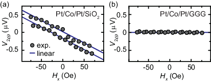
Next, to induce nonzero SOTs generated by the SHE, we use asymmetric Pt/Co/Pt structures. Figures 3(a) and 3(b) show the current-induced magnetization switching for the asymmetric Pt(5.0 nm)/Co(1.1 nm)/Pt(2.0 nm)/SiO2 and Pt(5.0 nm)/Co(1.1 nm)/Pt(2.0 nm)/GGG devices measured using the anomalous Hall effect (AHE); the anomalous Hall resistance was measured as a function of an in-plane dc current with applying an in-plane external magnetic field along -axis [see Fig. 1(a)]. In order to avoid thermal effects generated by the current, the experiment was conducted at 250 K. As shown in Figs. 3(a) and 3(b), by reversing the direction of the external in-plane magnetic field, the polarity of the magnetization switching is also reversed, which is consistent with the SHE-induced magnetization switching [4]. The corresponding switching phase diagrams (SPDs) are plotted in Figs. 3(c) and 3(d). Both SPDs show almost symmetric shapes, indicating the uniform reversal process [4]. By increasing the value of the in-plane magnetic field, the critical current decreases accordingly. With an in-plane magnetic field =100 Oe, the critical switching current is approximately 16 mA for the Pt/Co/Pt/SiO2 device, which yields to a current density of 1.97 A/cm2. For the Pt/Co/Pt/GGG device, is only 8 mA in the same condition of the in-plane magnetic field. By comparing the dependence on the perpendicular magnetic field of the two samples [see Fig. 3(e)], it is found that the Pt/Co/Pt/GGG device has a smaller slope during the magnetization switching, indicating a weaker perpendicular anisotropy field than the Pt/Co/Pt/SiO2 device. The weaker perpendicular anisotropy field results in a reduction of the critical switching current. By increasing to above 400 Oe, the magnetization switching becomes incomplete due to the too large tilting in the in-plane direction.
The above experimental results demonstrate that the Rashba effect is eliminated and nonzero spin Hall torque is responsible for the manipulation of the magnetization in the asymmetric Pt/Co/Pt structures. Here, the top and bottom Pt layers generate the damping-like torque in opposite directions (i.e., defined as and ), and the net effective field [4]
| (5) |
after the cancellation from both sides acts on the magnetization in the Co layer, where and are the saturation magnetization and thickness of the Co layer, respectively. and are the effective fields associated with and , respectively. and are the spin current density injected into the Co layer from the top and bottom Pt layers. For the Pt/Co/Pt trilayers, and are purely generated by the SHE because of the vanishingly small Rashba SOT. Thus, by measuring and by solving Eq. (1), the SHE in the Pt layers can be quantified. However, we found that the Pt/Co/Pt trilayer deposited on the SiO2 substrate is not a suitable system for precise measurements of . Figure 4(a) shows the magnetic field dependence of the second harmonic Hall voltage for the symmetric Pt(3.5 nm)/Co(1.1 nm)/Pt(3.5 nm)/SiO2 trilayer, where the in-plane magnetic field was applied along the -axis. For comparison, we show the dependence of for the symmetric Pt(3.5 nm)/Co(1.1 nm)/Pt(3.5 nm)/GGG trilayer in Fig. 4(b). Figure 4(a) shows that decreases clearly with for the symmetric Pt/Co/Pt/SiO2 trilayer. This indicates that the cancellation of the spin Hall torque from the top and bottom Pt layers is not complete in the Pt/Co/Pt/SiO2 device. By using the Eq. (2), is calculated to be Oe/Acm-2 for the symmetric Pt/Co/Pt/SiO2 device. The sign of the suggests that the magnitude of is larger than that of in spite of the same thicknesses of the top and bottom Pt layers on SiO2 substrate. Although the reason is not clear currently, this may be due to the influence of the SiO2 substrate. We fabricated Pt single layer films (3.5 nm) on SiO2 and GGG substrates simultaneously, and measured the resistivity by using four probes method, respectively. It is found that the resistivity of Pt on the SiO2 substrate (63.20 cm) is larger than which on the GGG substrate (50.19 cm). According to the previous study, a thin Pt film deposited on a SiO2 substrate is lack of strong adhesion between the Pt atoms and the SiO2 surface, which leads to a increase of the Pt resistivity [32]. This result is consistent with the vector measurement on the symmetric Pt/Co/Pt trilayers. Since in the symmetric Pt/Co/Pt/SiO2 device, if the bottom Pt layer has a larger resistivity than the top Pt layer, the magnitude of will be larger than because of the asymmetry of the charge current density. SiO2 substrates have been commonly used for fabricating spintronic devices and the magnitude of the SOT in these devices has been under debate recently. Our results reveal that carefully controlled experiments in different substrates are necessary to fully understand the spin-orbit physics in metallic heterostructures.
The complete cancellation of the SOTs from the top and bottom Pt layers, shown in Fig. 2, suggests that a Pt/Co/Pt trilayers on a GGG substrate is a suitable system for precise measurements of the spin Hall torque; the damping-like torque purely generated by the SHE can be quantified under the vanishingly small Rashba SOT by fabricating the trilayer with asymmetric thicknesses of the two Pt layers on a GGG substrate. In Figs. 5(a) and 5(b), we show the magnetic field dependence of the first and second harmonic Hall voltage signals for the asymmetric Pt(5.0 nm)/Co(1.1 nm)/Pt(2.5 nm)/GGG device at various temperatures , where the in-plane magnetic field was applied along the -axis. Using the result shown in Figs. 5(a) and 5(b) combined with Eq. (4), the temperature dependence of the damping-like effective field is obtained as shown in Fig. 5(c). The effective field is almost constant Oe/Acm-2 and it decreases only slightly with decreasing the temperature . Here, in the Hall measurements, the anomalous Nernst effect (ANE) can also be induced by current-induced inhomogeneous sample heating, which gives rise to additional contribution to the second harmonic voltage . The ANE contribution to can be determined by measuring the harmonic voltage as a function of the magnetic field along the direction, [18]. However, we observed that is negligible for the asymmetric Pt/Co/Pt structure as shown in Fig. 5(d), and thus we neglected the ANE contribution to in the present system.
To quantitatively discuss the temperature dependence of the damping-like torque shown in Fig. 5(c), we have solved the spin diffusion equation, Eq. (1). By taking into account the SHE in the top and bottom Pt layers with the boundary conditions in Pt/Co/Pt trilayers, i.e. at the surfaces of the Pt layers and continuity of and at the Pt/Co and Co/Pt interfaces, the net spin current density injected into the Co layer is obtained as
|
|
(6) |
where is the spin Hall angle of Pt. and are the spin diffusion length and electrical conductivity of Pt (Co). and are the thickness of the Co layer and top (bottom) Pt layer, respectively. is the applied charge current density in the Pt layer. The experimentally measured Oe/Acm-2 is quantitatively reproduced using Eqs. (5) and (6) with , nm, nm, m-1, m-1 [33, 34]. Here, emu/cm3, measured with a vibrating sample magnetometer, was used for the calculation. The slight decrease of the damping-like torque, purely generated by the SHE, by decreasing is mainly due to the temperature dependence of the saturation magnetization in the Co layer. As shown in Fig. 5(c), by assuming negligible temperature dependence of the other parameters, which is practical [35], the dependence of is well reproduced with Eqs. (5) and (6) using the measured at each temperature [Fig. 5(e)]. These results demonstrate the temperature-independent spin Hall angle of Pt. It should be noticed that the above calculated spin Hall angle of Pt here sets a lower bound, since the spin transparency and the spin memory loss (SML) at the Pt/Co interface have been neglected. Therefore, the actual internal spin Hall angle of Pt would be even larger. According to the previous work, the spin transparency at a Pt/Co interface is evaluated as [36]. By taking into account this value, the spin Hall angle of Pt in our devices is calculated to be around 0.36. This value is much larger than the previous reports on the spin Hall angle of Pt without considering the SML, while consistent with Pai ’s recent study, which reported that the spin Hall angle of Pt could be as high as 0.30 or even greater [37]. This suggets that by engineering the NM/FM interface, spintronics devices with high conversion effeciency might be realized.
IV IV. conclusions
In summary, we have demonstrated a quantitative study of the pure spin Hall torque in a large range of temperatures from 300 to 10 K. By intentionally fabricating Pt/Co/Pt trilayers with asymmetric thicknesses of the top and bottom Pt layers, the Rashba spin-orbit torques are largely eliminated. In order to precisely determine the value of the spin Hall torque, the complete cancelation of spin Hall torque has been verified by fabricating symmetric Pt/Co/Pt structure on SiO2 and GGG substrates. It is found that despite of the complete cancelation on the GGG substrate, the spin Hall torque cannot be completely canceled out when the top and bottom Pt layers have same thicknesses on the SiO2 substrate. This suggests that Pt/Co/Pt trilayers on a GGG substrate is a suitable system for precise measurements of the spin Hall torque. The result of the vector measurements for Pt/Co/Pt/GGG shows that the spin Hall angle of Pt is independent with the temperatures.
V acknowledgments
Acknowledgements.
This work was supported by PRESTO-JST “Innovative nano-electronics through interdisciplinary collaboration among material, device and system layers,” JSPS KAKENHI Grant Numbers 26220604, 26103004, 26600078, 26790037, the Mitsubishi Foundation, the Asahi Glass Foundation, the Mizuho Foundation for the Promotion of Sciences, and the Casio Science Promotion Foundation. H. A. and H. N. contributed equally to this work.References
- [1] I. M. Miron, K. Garello, G. Gaudin, P.-J. Zermatten, M. V. Costache, S. Auffret, S. Bandiera, B. Rodmacq, A. Schuhl, and P. Gambardella, Nature 476, 189 (2011).
- [2] I. M. Miron, G. Gaudin, S. Auffret, B. Rodmacq, A. Schuhl, S. Pizzini, J. Vogel, and P. Gambardella, Nat. Mater. 9, 230 (2010).
- [3] L. Liu, C.-F. Pai, Y. Li, H. Tseng, D. Ralph, and R. Buhrman, Science 336, 555 (2012a).
- [4] L. Liu, O. Lee, T. Gudmundsen, D. Ralph, and R. Buhrman, Phys. Rev. Lett. 109, 096602 (2012b).
- [5] J. Kim, J. Sinha, M. Hayashi, M. Yamanouchi, S. Fukami, T. Suzuki, S. Mitani, and H. Ohno, Nat. Mater. 12, 240 (2013).
- [6] G. Yu, P. Upadhyaya, Y. Fan, J. G. Alzate, W. Jiang, K. L. Wong, S. Takei, S. A. Bender, L.-T. Chang, Y. Jiang, et al., Nat. Nanotechnol. 9, 548 (2014a).
- [7] Y. Fan, P. Upadhyaya, X. Kou, M. Lang, S. Takei, Z. Wang, J. Tang, L. He, L.-T. Chang, M. Montazeri, et al., Nat. Mater. 13, 699 (2014).
- [8] M. Cubukcu, O. Boulle, M. Drouard, K. Garello, C. O. Avci, I. M. Miron, J. Langer, B. Ocker, P. Gambardella, and G. Gaudin, Appl. Phys. Lett. 104, 042406 (2014).
- [9] S. Woo, M. Mann, A. J. Tan, L. Caretta, and G. S. Beach, Appl. Phys. Lett. 105, 212404 (2014).
- [10] Z. Zhao, M. Jamali, A. K. Smith, and J.-P. Wang, Appl. Phys. Lett. 106, 132404 (2015).
- [11] K. Garello, C. O. Avci, I. M. Miron, M. Baumgartner, A. Ghosh, S. Auffret, O. Boulle, G. Gaudin, and P. Gambardella, Appl. Phys. Lett. 105, 212402 (2014).
- [12] R. Liu, W. Lim, and S. Urazhdin, Phys. Rev. B 89, 220409 (2014).
- [13] G. Yu, P. Upadhyaya, K. L. Wong, W. Jiang, J. G. Alzate, J. Tang, P. K. Amiri, and K. L. Wang, Phys. Rev. B 89, 104421 (2014b).
- [14] X. Wang, C. O. Pauyac, and A. Manchon, Phys. Rev. B 89, 054405 (2014).
- [15] M. Akyol, J. G. Alzate, G. Yu, P. Upadhyaya, K. L. Wong, A. Ekicibil, P. K. Amiri, and K. L. Wang, Appl. Phys. Lett. 106, 032406 (2015).
- [16] G. Yu, L.-T. Chang, M. Akyol, P. Upadhyaya, C. He, X. Li, K. L. Wong, P. K. Amiri, and K. L. Wang, Appl. Phys. Lett. 105, 102411 (2014c).
- [17] Q. Hao and G. Xiao, Phys. Rev. B 91, 224413 (2015).
- [18] K. Garello, I. M. Miron, C. O. Avci, F. Freimuth, Y. Mokrousov, S. Blügel, S. Auffret, O. Boulle, G. Gaudin, and P. Gambardella, Nat. Nanotechnol. 8, 587 (2013).
- [19] C. O. Avci, K. Garello, I. M. Miron, G. Gaudin, S. Auffret, O. Boulle, and P. Gambardella, Appl. Phys. Lett. 100, 212404 (2012).
- [20] J. Kim, J. Sinha, S. Mitani, M. Hayashi, S. Takahashi, S. Maekawa, M. Yamanouchi, and H. Ohno, Phys. Rev. B 89, 174424 (2014).
- [21] J. Torrejon, F. Garcia-Sanchez, T. Taniguchi, J. Sinha, S. Mitani, J.-V. Kim, and M. Hayashi, Phys. Rev. B 91, 214434 (2015).
- [22] C. Zhang, S. Fukami, H. Sato, F. Matsukura, and H. Ohno, Appl. Phys. Lett. 107, 012401 (2015a).
- [23] C. O. Avci, K. Garello, C. Nistor, S. Godey, B. Ballesteros, A. Mugarza, A. Barla, M. Valvidares, E. Pellegrin, A. Ghosh, et al., Phys. Rev. B 89, 214419 (2014).
- [24] M. Hayashi, J. Kim, M. Yamanouchi, and H. Ohno, Phys. Rev. B 89, 144425 (2014).
- [25] X. Fan, J. Wu, Y. Chen, M. J. Jerry, H. Zhang, and J. Q. Xiao, Nat. Commun. 4, 1799 (2013).
- [26] S. Emori, U. Bauer, S. Woo, and G. S. Beach, Appl. Phys. Lett. 105, 222401 (2014).
- [27] T. Yang, M. Kohda, T. Seki, K. Takanashi, and J. Nitta, Jpn. J. Appl. Phys. 53, 04EM06 (2014).
- [28] P. Haazen, E. Murè, J. Franken, R. Lavrijsen, H. Swagten, and B. Koopmans, Nat. Mater. 12, 299 (2013).
- [29] C. H. Sim, J. C. Huang, M. Tran, and K. Eason, Appl. Phys. Lett. 104, 012408 (2014).
- [30] M. Yang, K. Cai, H. Ju, K. W. Edmonds, G. Yang, S. Liu, B. Li, B. Zhang, Y. Sheng, S. Wang, Y. Ji, and K. Wang, Sci. Rep. 6, 20778 (2016).
- [31] T. Valet and A. Fert, Phys. Rev. B 48, 7099 (1993).
- [32] M.-H. Nguyen, D. C. Ralph, and R. A. Buhrman, Phys. Rev. Lett. 116, 126601 (2016).
- [33] M. Althammer, S. Meyer, H. Nakayama, M. Schreier, S. Altmannshofer, M. Weiler, H. Huebl, S. Geprägs, M. Opel, R. Gross, D. Meier, C. Klewe, T. Kuschel, J.-M. Schmalhorst, G. Reiss, L. Shen, A. Gupta, Y.-T. Chen, G. E. W. Bauer, E. Saitoh, and S. T. B. Goennenwein, Phys. Rev. B 87, 224401 (2013).
- [34] A. Ghosh, S. Auffret, U. Ebels, and W. Bailey, Phys. Rev. Lett. 109, 127202 (2012).
- [35] S. Meyer, M. Althammer, S. Geprägs, M. Opel, R. Gross, and S. T. Goennenwein, Appl. Phys. Lett. 104, 242411 (2014).
- [36] W. Zhang, W. Han, X. Jiang, S.-H. Yang, and S. S. Parkin, Nat. Phys. 11, 496 (2015b).
- [37] C.-F. Pai, Y. Ou, L. H. Vilela-Leão, D. Ralph, and R. Buhrman, Phys. Rev. B 92, 064426 (2015).