Normalized and Asynchronous Mirror Alignment
for Cherenkov Telescopes
Abstract
iact (iact) need imaging optics with large apertures and high image intensities to map the faint Cherenkov light emitted from cosmic ray air showers onto their image sensors. Segmented reflectors fulfill these needs, and as they are composed from mass production mirror facets they are inexpensive and lightweight. However, as the overall image is a superposition of the individual facet images, alignment is a challenge. Here we present a computer vision based star tracking alignment method, which also works for limited or changing star light visibility. Our method normalizes the mirror facet reflection intensities to become independent of the reference star’s intensity or the cloud coverage. Using two CCD cameras, our method records the mirror facet orientations asynchronously of the telescope drive system, and thus makes the method easy to integrate into existing telescopes. It can be combined with remote facet actuation, but does not require one to work. Furthermore, it can reconstruct all individual mirror facet point spread functions without moving any mirror. We present alignment results on the meter fact (fact).
Keywords:
Mirror alignment, computer vision, point spread function1 Introduction
The iact (iact) technique, with its large effective area, has opened the very high energy gamma ray sky to astronomy.
Almost [1] all former [2, 3], current [4, 5, 6, 7, 8], and future iact [9, 10] make use of segmented imaging reflectors with apertures up to m2 [6].
Segmented reflector facets can be mass produced cost-efficiently with an acceptable image quality.
Facets are much lighter than a monolithic mirror, which allows for very fast telescope repositioning, e.g. for gamma ray burst hunting.
However, there is one challenge to segmented reflectors.
This is the task of manipulating the mirror facet orientations and positions to improve the spatial image resolution or to reduce the psf (psf)’s size, also known as alignment.
Alignment needs to be done not only during installation but also in case of repair and replacement of facets.
To find the few gamma ray induced events in the far more numerous class of hadronic cosmic ray induced events, the air shower records are analyzed for geometrical and temporal features.
Higher image contrast, more isochronous photon arrivals, less image distortions, and higher spatial image resolution all help to lower the trigger and energy threshold of an iact and further help to better reconstruct the energies and source positions of the primary particles.
This makes alignment and mirror facet orientation determination important for an iact.
Above this, determining the mirror facet orientations without manipulation of the facets orientations or positions is desirable to put the mirror facet orientations in the iact simulations, which rely on precise input to calibrate the iact.
2 Current methods
To tackle the challenge of alignment, several approaches are in use.
We can summarize them in three categories.
First, there is the 2 method and its more general equivalent Bokeh alignment [11].
Both can be performed with simple hardware and minimal to no software.
With an artificial light source, the mirror facets are aligned without the need for clear nights or star light.
However, 2 alignment is geometrically very restricted [12, 3] and struggles to reach the most inner facets.
The novel Bokeh alignment is less restricted but was not yet performed on typical observation elevations to correct for gravitational slump.
In the first simple implementation of Bokeh alignment on an iact, which was limited by the thin lens approximation, the method did not yet reach the same high quality psf as the star tracking methods [11].
Second, there are methods which do direct psf investigations on a tracked star using a dedicated image screen [13, 6].
While achieving high psf quality these methods make extensive use of mirror facet orientation actuation during alignment.
Because of overcoming the psf facet ambiguity using the mirror facet actuation, the run time of these methods scales linear with the number of facets.
Third, there is the veritas raster method [14] which is based on the sccan [15] method.
Synchronized with the telescope’s drive, the telescope rasters a grid on the sky dome close to a star while the mirror facets surfaces are recorded by a CCD camera, positioned in the reflector’s focal point.
In contrast to the direct psf observations, many different pointing positions are needed to restore the mirror facet psf but on the other hand the raster method’s run time is constant in the number of facets.
Since the facet reflections are recorded through out the whole process of grid pointing, the method works best when the reference star’s light intensity is steady over time, which favors clear nights and sticking to one particular reference star.
Combining two records on different reference stars is not straight forward since the stars might have different light intensities.
Also there is extensive bi-directional communication to the telescope drive, which needs a software interface.
Here we present an enhanced alignment system based on the veritas raster scan method.
We implement a second CCD camera, that observes the reference star.
Using the star’s intensity observed in the second camera, our method normalizes the facet reflection intensities.
Further the second camera is used to estimate the telescope’s relative pointing, which makes communication to the telescope drive obsolete by recording asynchronously of it.
We call it namod (namod).
namod can combine records taken on different reference stars flexibly.
namod can reconstruct all individual mirror facet psf and facet orientations without needing actuated facets.
It delivers high psf quality while allowing alignment for a wider range of night sky conditions.
We present our implementation of namod on the 10 th scale mock up Mini fact and our namod implementation’s alignment performance on the fact (fact), a m class iact on the Canary island La Palma, Spain.
3 Method and Implementation
Our namod implementation uses two digital cameras, see Figure 1. First, the reflector camera monitors all the reflector’s facets and is mounted in the focal point of the reflector. Second, the star camera is mounted parallel to the telescope’s optical axis and observes the same part of the night sky as the telescope.


Our namod computer program reads out and adjusts both cameras. To determine the facet orientations, the telescope is pointed to a bright reference star in the night sky, see Figures 2 and 3. While the telescope moves close to the star, our namod program, asynchronously from the telescope’s drive, acquires images of the two cameras. Both random or spiral telescope movements close to the star are possible. The size of the region to move in depends on the pre-alignment state of the reflector. The better the pre-alignment, the smaller is the region to move in, the faster the namod acquisition is done, see Section 4. To later reconstruct the psf of the mirror facets, our namod program records the telescope’s relative pointing and the star’s intensity as well as the mirror facets reflection intensities … of all the facets. Instead of communicating with the drive of the telescope, our namod program restores directly from the star camera images.

During a namod recording, the reference star’s light intensity changes, e.g. due to clouds or varying zenith distance of the reference star. Also, changes when switching to another star. All these changes in reduce the capability of reconstructing the facet orientations because the light intensities observed in the reflections of the mirror facets depend on the reference star. The namod method addresses this challenge by normalizing using , see Section 3.4. This way, the mirror facet orientations are recorded more independent of the sky quality or the reference star. After the recording is done: First the mirror facets psf are reconstructed, see Section 3.5. Second, the orientation of each facet is calculated using the reflection law and the reconstructed facet’s psf, see Section 3.6. An overview of our implementation and example images are shown in Figure 4.
3.1 Cameras, calibration and control
We use two industrial digital cameras for our namod implementation, see Table 1.
First, a highly responsive Mpixel camera and a wide angle lens serve as reflector camera, see Figure 5.
Second, a Mpixel camera with a high mapping quality lens is used as star camera, see Figure 6.
We use the same cameras on Mini fact and fact.
 Figure 5: Reflector camera mounted on Mini fact directly in the focal point.
 Figure 6: Star camera mounted on Mini fact using a fine pan and tilt joint.
| reflector camera | star camera | |
|---|---|---|
| Type designation | IDS DCU223C | IDS UI-1480SE-M-HQ |
| Optics [mm] | Im. Source | Zeiss Pentacon |
| Sensor/color | CCD/RGB | CMOS/B&W |
| Resolution [pixels] | ||
| Communication | USB 2.0 | USB 2.0 |
| FoV short edge [Deg] | ||
| Radiom. , , | ,, | ,, |
| pixel resolution mDeg/pixel | - |
To compare the light intensity observed in both cameras, the radiometric properties of the cameras have been measured. Knowing the exposure time and the response of a pixel , our namod program calculates the absolute light intensity , which is proportional to the photon intensity in this pixel. In our implementation we use
| (1) |
to reconstruct .
The two slopes and as well as the offset are measured in the lab by taking exposure time series while facing a reference light source at various distances with the bare image sensors.
More than three orders of magnitude in light intensity are taken into account during calibration, and thus makes our camera and lens combinations sensitive to stars from about down to in apparent magnitude.
To estimate , the camera response must not overflow or underflow.
Our namod program runs a feedback loop, which alters the exposure times of the star and reflector camera such that both maximum responses are always close to saturation.
Over or under saturated images are neglected automatically followed by an exposure time adjustment and reacquisition.
Typical acquisition rates for our namod implementation are Hz to Hz, depending on the star and the sky quality, while is about ms up to s.
A calibration of the geometric properties of the star camera together with its lens is taken into account in order to later reconstruct the relative pointing directions , from the star camera images.
Since the star camera lens distortion turned out to be negligible, an affine mapping relation is used where the angular resolution of a pixel is shown in Table 1.
For radiometric and geometric calibration we use methods inspired by [16] and [17].
3.2 Reference star identification
Our namod program identifies stars in the star camera image to estimate the relative telescope orientation , and to measure the star’s intensity . Our program accepts star images where only a single dominant star is present and where the shape and the size of the star is within an expected margin. In our implementation we look for dominant stars with intensities standard deviations above the initial image noise level and accept spatial sizes of about . If a star image is rejected, both star and reflector image are discarded and acquired again.
3.3 Mirror facet identification
The namod method needs to know which pixel intensities of the -th reflector image belong to a specific mirror facet so that the mirror facets reflection intensity can be averaged from these pixel intensities. In our implementation, the namod program is fed polygons describing mirror facets. The polygons can have individual shapes and sizes. To define the polygons, a reflector camera image is used while all the facets edges are visible, see Figure 12.
3.4 Normalizing the mirror responses
In our namod implementation, we extract for each record the reflection intensity of the -th mirror facet from the reflector camera image as well as the star’s intensity from the star camera image. We obtain the normalized mirror facet reflection response
| (2) |
by division. Figure 13 shows the performance of our radiometric camera calibration and the resulting normalization stability .
3.5 psf (psf) reconstruction
By recording the normalized reflected intensity of the -th mirror facet for many different pointings and , the namod method records the psf of the -th mirror facet directly.
In our implementation of namod, we export the mirror facets psf using D histograms because these are easy to interpret and work with.
To fill the final , we take the exposure map of the pointings and into account.
This is done as the telescope movement might be unevenly spread along the D pointing range.
First, we fill for each mirror facet a weighted D histogram .
The normalized mirror response of each record is filled into the bins of according to the corresponding pointing and .
Second, we fill a D exposure histogram to count the numbers of records taken in a specific pointing bin.
We then obtain the final D psf histogram for each mirror facet , by bin wise dividing the facet’s raw response using the exposure histogram: .
Figure 14 shows example psf histograms recorded with our namod implementation.
3.6 Correction Implementation
After recording and reconstruction of the individual mirror facet psf , our namod implementation produces both human and machine readable instructions to correct the facet misalignments. First, we calculate the position of the cog (cog) in for each facet with respect to the reflectors focal point. Second, we calculate the correction angle to be applied to the -th mirror facet using the reflection law
| (3) |
Our namod program knows the inverse kinematics of the mirror facet mountings of fact so it can further give directly the manipulation instructions for the three linear joints of a mirror facet’s tripod mount. Figure 12 shows an example of our namod program’s instructions.
3.7 The namod development mock-up – Mini fact
Our namod implementation was developed on a mock-up called Mini fact in order to not lose observation time on fact. Mini fact is a 10th scale model of FACT with similar tripod mirror facet mounting, see Figure 7 and Table 2. It has a fully operational segmented reflector of 30 facets and has a angular resolution comparable to fact.
| Focal length and F-number | mm, |
|---|---|
| Aperture | hexagons, each cm2, total cm2 |
| Geometry | Davies-Cotton and/or Paraboloid |
| Mirror facets | Float glass, front aluminum coated, spherical |

4 Results
4.1 Fine alignment of fact in May 2014

| focal length | m |
|---|---|
| number of facets | |
| facet mounting | manual adjustment on tripod |
| reflector geometry along optical axis | Davies Cotton + parabola |
| reflector area | m2 |
| effective reflector area | m2 |
| effective aperture diameter | m |
| maximum aperture diameter | m |
| effective F-number, | |
| F-number, | |
| image sensor diameter, FoV | m, Deg |
Reflector redesign and need for new alignment
In May 2014 we redesigned the fact reflector, see Figure 8 and Table 3, to be a hybrid of Davies Cotton [19] and paraboloid geometry to decrease the reflector’s time spread with an acceptable worsening of its spatial resolution. Since fact’s overall timing precision of ns used to be in the regime of the reflector’s time spread, we changed the reflector’s geometry to further improve the overall timing precision [20] and lower the minimal energy trigger threshold.
Numerical psf comparison
For numerical guidance, we compare the areas of the different psf before and after the namod alignment, see Table 4. The area
| (4) |
is defined by the ellipse spanned by the standard deviations
| (5) |
of the light intensity distribution along its principal components. Here gives the eigenvalues of matrix and gives the covariance matrix of the distribution . The ellipses and the corresponding principal component directions are highlighted in red in the Figures 9, 10 and 11.
pre-alignment
After the redesign, we performed a first pre-alignment using the most simple version of Bokeh alignment [11], which led to the overall psf shown in Figure 9. The small pre-alignment psf sped up the following namod alignment since the movements close to the reference star could be limited to a region of the size of the pre-alignment psf of in diameter.
namod alignment
After pre-alignment, our namod alignment fine tuned the fact reflector in a single iteration resulting in the psf shown in Figure 10. For this particular namod alignment, our implementation took about 1300 records in hour. Figure 12 shows the instructions provided by our namod implementation, which were applied to fact’s mirror tripod mount joints manually using a goniometer. Deformation tests on FACT showed, that gravitational slump is not an issue on its reflector, but to be sure in this first namod alignment, we chose only reference stars within zenith distance.
Theoretical lower psf limit
Direct psf recording with dedicated image sensor
The psf in figures 9 and 10 are recorded with our radiometrically calibrated cm2 digital image sensor, that is placed in fact’s pseudo focal plane while tracking the star Arcturus. This image sensor is made out of a vintage medium format camera’s view finder screen (Hasselblad ), which is observed by an industrial CCD camera and has an effective resolution of pixels, respectively mDeg/pixel when mounted on the fact reflector.
| Reflector state | [arcmin2] | relative [%] |
|---|---|---|
| before reconfiguration | 1088 | |
| after reconfiguration | too large to be recorded | too large |
| after Bokeh alignment | 1149 | |
| after namod alignment | 260 | |
| ray tracing, perfect reflector | 100 |


4.2 Independence of night sky conditions
Two years after the initial radiometric calibration of the two cameras in our namod implementation, we checked the normalization again, in the lab, and directly on a Mini fact facet. Mini fact was pointing to an artificial light source of adjustable intensity while our namod setup was taking records. Figure 13 shows the recorded ’star’ intensity and the normalized mirror intensity . The normalized mirror intensity changes only when changes by one order of magnitude, respectively it changes for one step of in apparent magnitude.
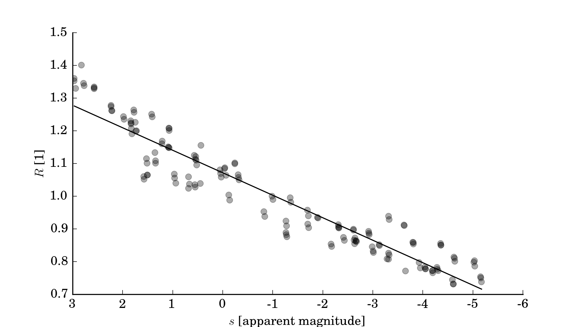
Our namod implementation aligned Mini FACT several times successfully on the partly clouded night sky of Dortmund, Germany. Unusable records were rejected automatically and we did not notice a drop in psf reconstruction quality although the reference stars and their intensities changed during the process. This shows, that our namod implementation’s intensity normalization helps to reconstruct the facets orientations more independent of the sky conditions across the full range of possible reference star magnitudes.
4.3 psf reconstruction performance
To demonstrate the performance and repeatability of our namod implementation, we show that the individual mirror facet psf signatures can be identified for two namod runs, separated by one year, see Table 5. Without moving or tilting the facets, our namod implementation recorded the facets orientations to feed the fact iact simulation so that mismatches between observed and simulated air shower records can be reduced.
| May 2014 | May 2015 | |
|---|---|---|
| records taken | 1 k | 5 k |
| reference object | star Arcturus | planet Jupiter |
| zenith distance | ||
| recording time | min | h min |
Figure 14 shows a sample of reconstructed s for individual fact mirror facets. The more dense of the year 2015 reveals the psfs of this year in more detail.


5 Conclusion
Our namod implementation is stable and delivered a high quality psf during its first use.
In a single iteration on fact, our namod implementation narrowed the psf area down from to only of the theoretical psf area limit found in ray tracing simulations, where the ray tracing was done for perfect mirror facets and a perfect alignment.
The mirror facet reflection normalization allows to switch to various reference stars during recording and makes facet orientation reconstruction less dependent on changes in sky quality or zenith distance.
The absence of telescope drive communication, and the flexible feeding of facet geometry makes our namod implementation a simple to use, plug and play solution, that can be applied to similar telescopes easily.
For example it can be applied to Mini fact, which runs a completely different drive software.
The pocket Mini fact mock up sped up the development of our namod implementation while no observation time was lost on fact.
In future implementations one might install the namod cameras permanently.
On fact, our namod implementation was mounted temporary but a permanent installation is possible when placing the reflector camera and the pseudo optical axis on top of the lid of the telescope’s image sensor.
The reflection coefficients of the mirror facets might be determined as well.
The normalization stability might be further improved by not using electric light bulbs but light sources with a spectral distribution closer to the one of stars.
Also, the namod records might be used to validate the ray tracing iact simulation when used as directional look up table for a given aperture intersection.
An adaptation of namod on the dual mirror Schwarzschild Couder telescopes of the Cherenkov Telescope Array (CTA) [9] is not straight forward.
However, because of the psf quality, but especially because of the flexibility and the tolerance for a wider range of night sky conditions, we believe namod is ideal for the future single mirror (single primary segmented reflector) telescopes of CTA.
Acknowledgments
The important contributions from ETH Zurich grants ETH-10.08-2 and ETH-27.12-1 as well as the funding by the German BMBF (Verbundforschung Astro- und Astroteilchenphysik) are gratefully acknowledged. We are thankful for the very valuable contributions from E. Lorenz, D. Renker and G. Viertel during the early phase of the project. We thank the Instituto de Astrofisica de Canarias allowing us to operate the telescope at the Observatorio Roque de los Muchachos in La Palma, the Max-Planck-Institut fuer Physik for providing us with the mount of the former HEGRA CT 3 telescope, and the MAGIC collaboration for their support. We would also like to thank the OpenCV community, the StackOverflow community, J. Hunter for Matplotlib, the GNU compiler community, IDS imaging for excellent product documentation and H. Mueller and J. Stratmann for discussions on vintage optics.
References
References
- [1] T. Hara, T. Kifune, Y. Matsubara, Y. Mizumoto, Y. Muraki, S. Ogio, T. Suda, T. Tanimori, M. Teshima, T. Yoshikoshi, et al., A 3.8 m imaging Cherenkov telescope for the TeV gamma-ray astronomy collaboration between Japan and Australia, Nucl. Instrum. Meth. A 332 (1) (1993) 300–309.
- [2] D. A. Lewis, Optical characteristics of the Whipple observatory Tev gamma-ray imaging telescope, Experimental Astronomy 1 (4) (1990) 213–226.
- [3] A. Barrau, R. Bazer-Bachi, E. Beyer, H. Cabot, M. Cerutti, L. Chounet, G. Debiais, B. Degrange, H. Delchini, J. Denance, et al., The CAT imaging telescope for very-high-energy gamma-ray astronomy, Nucl. Instrum. Meth. A 416 (2) (1998) 278–292.
- [4] J. Holder, R. Atkins, H. Badran, G. Blaylock, S. Bradbury, J. Buckley, K. Byrum, D. Carter-Lewis, O. Celik, Y. Chow, et al., The first VERITAS telescope, Astroparticle Physics 25 (6) (2006) 391–401.
- [5] K. Bernlöhr, O. Carrol, R. Cornils, S. Elfahem, P. Espigat, S. Gillessen, G. Heinzelmann, G. Hermann, W. Hofmann, D. Horns, et al., The optical system of the HESS imaging atmospheric Cherenkov telescopes. Part I: layout and components of the system, Astroparticle Physics 20 (2) (2003) 111–128.
- [6] R. Cornils, K. Bernlöhr, G. Heinzelmann, W. Hofmann, M. Panter, The optical system of the HESS II telescope, in: International Cosmic Ray Conference, Vol. 5, 2005, p. 171.
- [7] C. Baixeras, M. Collaboration, et al., The MAGIC telescope, Nuclear Physics B-Proceedings Supplements 114 (2003) 247–252.
- [8] H. Anderhub, M. Backes, A. Biland, V. Boccone, I. Braun, T. Bretz, J. Buß, F. Cadoux, V. Commichau, L. Djambazov, et al., Design and operation of FACT – the First G-APD Cherenkov Telescope, Journal of Instrumentation 8 (06) (2013) P06008.
- [9] B. S. Acharya, M. Actis, T. Aghajani, G. Agnetta, J. Aguilar, F. Aharonian, M. Ajello, A. Akhperjanian, M. Alcubierre, J. Aleksić, et al., Introducing the CTA concept, Astroparticle Physics 43 (2013) 3–18.
- [10] Y. Igor, et al., Imaging Camera and Hardware of Tunka-IACT, in: Proceedings of the 34th ICRC, Vol. 986, 2015.
- [11] M. L. Ahnen, D. Baack, M. Balbo, M. Bergmann, A. Biland, et al., Bokeh Mirror Alignment for Cherenkov Telescopes, submitted to Astroparticle Physics.
- [12] J. Toner, V. Acciari, A. Cesarini, G. Gillanders, D. Hanna, G. Kenny, J. Kildea, A. Mccann, M. Mccutcheon, M. Lang, et al., Bias alignment of the VERITAS telescopes, in: Proceedings of the 30th International Cosmic Ray Conference, Vol. 3, 2008, p. 1401.
- [13] A. Biland, M. Garczarczyk, H. Anderhub, V. Danielyan, D. Hakobyan, E. Lorenz, R. Mirzoyan, M. Collaboration, The Active Mirror Control of the MAGIC Telescope, in: Proceedings of the 30th ICRC, Vol. 533, 2007, pp. 1353–1356.
- [14] A. McCann, D. Hanna, J. Kildea, M. McCutcheon, A new mirror alignment system for the VERITAS telescopes, Astroparticle Physics 32 (6) (2010) 325–329.
- [15] F. Arqueros, G. Ros, G. Elorza, D. Garcia-Pinto, A technique for the optical characterization of imaging air-Cherenkov telescopes, Astroparticle Physics 24 (1) (2005) 137–145.
- [16] D. A. Forsyth, J. Ponce, Computer Vision – A Modern Approach, Pearson Education Inc., New Jersey U.S.A., 2003.
- [17] C. Wöhler, 3D Computer Vision: Efficient Methods and Applications, Springer Science & Business Media, 2012.
- [18] V. Fonseca, Status and Results from the HEGRA Air Shower Experiment, Astrophysics and space science 263 (1-4) (1998) 377–380.
- [19] J. M. Davies, E. S. Cotton, Design of the Quartermaster Solar Furnace, Solar Energy 1 (2) (1957) 16–22.
- [20] M. Noethe, et al., FACT – Calibration of Imaging Atmospheric Cherenkov Telescopes with Muon Rings, in: Proceedings of the 34th ICRC, Vol. 733, 2015.
- CoG
- Center of Gravity
- SCCAN
- Solar Concentrator Characterization At Night
- PSF
- Point Spread Function
- FACT
- First Geiger-mode Avalanche Cherenkov Telescope
- VERITAS
- Very Energetic Radiation Imaging Telescope Array System
- IACT
- Imaging Atmospheric Cherenkov Telescope
- NAMOD
- Normalized and Asynchronous Mirror Orientation Determination