Novel magnetism on a honeycomb lattice in -RuCl3 studied by muon spin rotation
Abstract
Muon spin rotation measurements have been performed on a powder sample of -RuCl3, a layered material which previously has been proposed to be a quantum magnet on a honeycomb lattice close to a quantum spin liquid ground state. Our data reveal two distinct phase transitions at 11 K and 14 K which we interpret as originating from the onset of three-dimensional order and in-plane magnetic order, respectively. We identify, with the help of density functional theory calculations, likely muon stopping sites and combine these with dipolar field calculations to show that the two measured muon rotation frequencies are consistent with two inequivalent muon sites within a zig-zag antiferromagnetic structure proposed previously.
pacs
76.75.+i, 75.10.b, 71.15.Mb, 61.05.cpSolid-state systems with architectures that contain triangles or tetrahedra offer the possibility of realizing novel magnetically frustrated states, such as quantum spin liquids [1] or exotic topological phases [2]. One such candidate system for frustrated magnetism is -RuCl3, which adopts the honeycomb structure. It is thought to be a spin-orbit assisted Mott insulator [3, 16], in which both the near two-dimensionality of the separate honeycomb layers and bond-dependent interactions, which may embody Kitaev physics, are proposed to be major ingredients [5]. Unconventional excitations observed via Raman [6] and inelastic neutron scattering [12] have been presented as evidence that -RuCl3 may be close to a quantum spin liquid ground state. Various magnetic transitions have been reported in -RuCl3 with early studies pointing towards an antiferromagnetic transition with numerous reported temperatures of K [8], K [9] or even K [10], while later investigations proposed a potential second transition around K [11, 12, 13] thought to originate from low-moment magnetism. Recent neutron powder diffraction provided evidence for a single transition to a zig-zag antiferromagnetic state with 2-layer stacking at K [6], though a later single crystal neutron study has proposed a single transition at K to a 3-layer stacking magnetic order in pristine single crystals and a change of to K upon mechanical deformation of the crystals [7]. These differences in observed properties could be due to the propensity of this compound to exhibit stacking faults between the weakly coupled honeycomb layers [6].
Positive muons as local magnetic probes present an ideal tool for detecting magnetic order and characterizing magnetic behavior, and have been extensively utilized in muon-spin rotation or relaxation (SR) studies of frustrated systems [16]. Here, we present results from zero-field (ZF) SR investigations of -RuCl3 powder complemented by a theoretical analysis based on density functional theory (DFT) and dipolar field calculations. Below about K our sample shows clear evidence for long-range magnetic order, with two muon precession signals resolvable at low temperature. However, there are clear indications of the higher frequency signal vanishing at a slightly lower temperature of about K.
Polycrystalline samples of -RuCl3 were synthesized by vacuum sublimation from commercial RuCl3 powder (Sigma Aldrich), which was sealed in a quartz ampoule ( mbar) and placed in a three-zone furnace with a hot and cold end of and , respectively. Those temperatures were chosen in order to obtain phase-pure -RuCl3 (the -polytype transforms irreversibly into the -phase above ) and to keep the Cl2 gas pressure in the ampoule below atmospheric pressure. The polycrystalline material harvested from the ampoule contained many plate-like shiny crystals of hexagonal shape. X-ray diffraction confirmed the samples to be single phase and in agreement with the structure [6, 7]. See the Supplemental Material [17] for more details on the X-ray characterization.
We conducted ZF SR measurements of a powder sample of -RuCl3 on the EMU spectrometer at the ISIS muon facility, RAL (UK), as well as the GPS spectrometer at the Swiss Muon Source, PSI (Switzerland). Data were collected in the temperature range K to K using 4He cryostats. In a SR experiment spin-polarized muons are implanted into a sample, where they Larmor-precess around the local magnetic field at the muon stopping site. By measuring the angular distribution of the decay product positrons the spin polarization can be tracked. In the case of long-range magnetic order, coherent magnetic fields at particular muon stopping sites within the unit cell lead to oscillatory signals with frequencies dependent on the local magnetic fields at each site. In SR impurity phases only contribute according to their volume fraction, and so the technique is an effective measure of intrinsic behavior.
Representative raw data obtained are plotted in Fig. 1(a) with Fourier transform spectra presented in Fig. 1(b). The measurements reveal oscillations below K with two clearly separate frequencies at low temperatures around MHz and MHz, resulting from two inequivalent muon stopping sites with local fields of mT and mT, respectively.
The SR data can be well fitted below K with a sum of two oscillating functions multiplied by exponentials of the form , allowing for relaxation caused by slow dynamics of the magnetic moments. In the range only one such oscillating component is required. Figure 2 presents the resulting frequencies , relaxation rates and oscillation amplitudes of the precession signals for the data collected on the GPS spectrometer. Essentially identical results were obtained in a separate experiment using the EMU spectrometer, demonstrating reproducibility. The fitted parameters can be modeled with a phenomenological order parameter equation of the form to give critical temperatures of K and K for the high and low frequency components, respectively. The presence of two SR precession signals necessitates two inequivalent muon stopping sites in the magnetic phase of our sample, whose origin we discuss later.
Further analysis requires the knowledge of the potential muon stopping sites. Therefore, we employ DFT calculations to map out the electrostatic Coulomb potential of -RuCl3 throughout its unit cell. The maxima of such a potential map have been a reliable approximation to the muon sites in previous more in-depth “DFT+” calculations, which also accounted for local distortions of the lattice caused by the muon presence [8, 10, 20].
We performed DFT calculations within the generalized gradient approximation [21] by employing the full potential linearized augmented plane wave (LAPW) basis as implemented in WIEN2k [13]. The parameter was set to 9 and we used a mesh of 800 points in the first Brillouin zone. The electrostatic (Coulomb) potential was calculated from the converged electron density and the three-dimensional electrostatic potential maps were obtained with the XCrySDen package [23] and visualized with the Vesta software [5].
The Coulomb potential of -RuCl3 calculated via DFT is plotted in Figure 3, with the global maximum of the potential chosen as the reference value. A large Coulomb potential corresponds to a low energy required to add a positive charge. Therefore, by considering regions of high electrostatic potential, and particularly local maxima, we can identify plausible regions for a muon to stop in. When additionally taking into account that we expect a to implant near a Cl- ion [17], we find four plausible muon site candidates, which are shown in Figure 3 and summarized in Table 1. These candidate sites are separated by up to eV in their Coulomb potential values, with the origin (Mu1) being the lowest. While the muon will generally perturb its local environment, its effect is short-ranged and significant only for the nearest neighbor ions [8, 10], and in the present case we anticipate only a small displacement of a nearest Cl- ion and negligible effect on the magnetic moment carrying Ru3+ ions. As a result, we do not expect distortions to have a significant impact on the bulk magnetism probed in our SR measurement.

| Atom | WP | SS | x | y | z |
| Ru | 4g | 2 | 0 | 0.33441 | 0 |
| Cl | 4i | m | 0.73023 | 0 | 0.23895 |
| Cl | 8j | 1 | 0.75138 | 0.17350 | 0.76619 |
| Mu1 | 2a | 2/m | 0 | 0 | 0 |
| Mu2 | 4i | m | 0.14 | 0 | 0.36 |
| Mu3 | 4g | 2 | 0 | 0.2 | 0.5 |
| Mu4 | 2d | 2/m | 0.5 | 0 | 0.5 |
We now calculate the local magnetic field experienced by an implanted muon. This field is in general a sum of contributions due to dipolar couplings, demagnetizing and Lorentz fields and hyperfine interactions. Since -RuCl3 orders antiferromagnetically the demagnetizing and Lorentz fields are zero. We expect the to stop near Cl- ions and thus direct overlap with any Ru3+ electron spin density will be tiny and so we neglect any hyperfine contribution [8, 9]. Therefore, we focus on the dominant dipole field only, which for a muon at position and magnetic moments at is given by
| (1) |
where .
There exists substantial knowledge about the magnetic structure of -RuCl3 based on neutron diffraction experiments. One neutron powder study provided evidence for a zig-zag antiferromagnetic order within each Ru honeycomb layer with an additional antiferromagnetic stacking between the layers. The corresponding propagation vector is , and moreover the moments are constrained to lie in the plane and the lower limit of the moment size is [6]. However, another recent single crystal measurement proposed an alternative zig-zag antiferromagnetic ordering with 3-layer stacking () in pristine single crystals with moments aligning in the plane in a spiral or collinear pattern [7]. Investigations using ab initio and model calculations also find an in-plane zig-zag antiferromagnetic order [11, 27] and predict the magnetic moments to make an angle of with the plane [11, 28].
Using the known crystal structure and the proposed 2-layer magnetic ordering we computed the dipole field strength at the candidate muon sites obtained through DFT simulations. Figure 4 displays the resulting Larmor frequencies and how they change as a function of the magnetic moment direction within the plane. Note that the dipole field vanishes due to the local symmetry at candidate site Mu1, which is the electrostatically most favourable one. Figure 4 reveals that there is no single moment direction within the plane for which we obtain precession frequencies that agree with both the experimentally observed ones. We can improve our estimates by incorporating the fact that we expect the muon to form a bond with a nearby Cl- ion of length [17]. Our revised model considers the muon site to be displaced from our earlier candidate sites towards each of the nearest Cl- ions. Figure 5 presents the resulting muon precession frequencies as a function of the magnetic moment direction. It shows that if we take the moment to be at with the plane [11] and small distortions towards the nearest neighbor Cl- ions both the Mu1 and Mu3 site candidates are compatible with the experimentally observed frequencies. It should be noted that both Mu1 and Mu3 have six nearby Cl- ions, four of which are at the Wyckoff positions and two of which are at the Wyckoff positions (see Table 1). We also considered the effect of stacking faults at which the RuCl3 layers are translated by [6]. We find that such faults can result in a lowering of the precession frequency from muons at the Mu1, Mu2 and Mu4 sites, but also different symmetry-equivalent sites can become inequivalent which could be a source of broadening [17]. However, stacking faults only have a significant effect on the precession signals if the muon is directly adjacent to the fault [17] and so we conclude that our data are dominated by effects due to the fault-free structure. In conclusion, the zig-zag antiferromagnetic order with 2-layer stacking proposed by Johnson et al. [6] is compatible with our SR measurements of -RuCl3 powder.
We considered two plausible scenarios that could explain the two observed frequencies and transitions. First, we investigated the possibility that there could be two distinct magnetic phases, one resulting from regular stacking of the layers and another from an alternative stacking proposed previously [7]. However, our test DFT calculations [17] showed this second structure to be energetically less favorable, and moreover the second phase would not produce a distinct dipole-field signature from the first. Second, we explored the possibility that the known presence of stacking faults [6], which likely lead to a complex sequence of interlayer exchange interactions, could hinder the establishing of long-range order along . Our simulations [17] show that a site near Mu1 is relatively insensitive to the magnetic configuration along . Thus, if order only locked in below 11 K, a muon at this site would not be affected and would produce a precession signal all the way up to 14 K. However, a Mu2 or Mu3 site is found to be more sensitive to the interlayer magnetic configuration and would detect a range of frequencies if order is not established. Such a site could plausibly give rise to the higher frequency signal that only sets in below 11 K. This second scenario is consistent with our experimental observations.
We repeated the dipole field analysis for the magnetic ordering with 3-layer stacking that Cao et al. have proposed for pristine single crystals of -RuCl3 [7]. While the resulting precession frequencies are all of the same order of magnitude as the experimentally observed ones, in general the 3-layer stacking leads to more than two observable frequencies to be expected, unless the frequencies due to muons stopping in the different layers and near the two types of Cl- ions are equal because of the symmetry of the muon sites [17]. We conclude that the magnetic ordering with 3-layer stacking is not compatible with our powder results, though we cannot rule out their applicability to the single crystal samples of Ref. [7].
In conclusion, we have conducted SR measurements of a powder of -RuCl3 and confirmed a transition to long range magnetic order below K, with a second transition at K. Using DFT calculations we identified candidates for the muon stopping site and analyzed the muon precession frequencies due to dipolar couplings at these sites, using two zig-zag antiferromagnetic structures proposed by recent powder and single crystal neutron diffraction studies and ab initio calculations. After examining a number of possible scenarios, we find that our results are consistent with a 2-layer ordering proposed by Johnson et al. [6] and we suggest an interpretation of our two transitions based on an intermediate temperature regime where two-dimensional, but not three-dimensional order, is established.
Acknowledgements.
This work is supported by EPSRC (UK) grants No 1380739 and No EP/M020517/1. Y. Li acknowledges support through a China Scholarship Council (CSC) Fellowship. R. Valentí thanks the Deutsche Forschungsgemeinschaft (DFG) for funding through grant SFB/TR49. We are also grateful for H. Lütkens providing technical assistance with the experiments at PSI, A. J. Steele for help with the dipole field calculations, R. Coldea for numerous insightful ideas and valuable conversations, and W. Hayes and S. Winter for useful discussions.References
- [1] L. Balents, Nature 464, 199 (2010).
- [2] G. Jackeli and G. Khaliullin, Physical Review Letters 102, 017205 (2009).
- [3] X. Zhou, H. Li, J. Waugh, S. Parham, H.-S. Kim, J. Sears, A. Gomes, H.-Y. Kee, Y.-J. Kim, and D. Dessau, (2016), arXiv:1603.02279 .
- [4] I. Pollini, Physical Review B 50, 2095 (1994).
- [5] K. W. Plumb, J. P. Clancy, L. J. Sandilands, V. V. Shankar, Y. F. Hu, K. S. Burch, H.-Y. Kee, and Y.-J. Kim, Physical Review B 90, 041112 (2014).
- [6] L. J. Sandilands, Y. Tian, K. W. Plumb, Y.-J. Kim, and K. S. Burch, Physical Review Letters 114, 147201 (2015).
- [7] A. Banerjee, C. A. Bridges, J.-Q. Yan, A. A. Aczel, L. Li, M. B. Stone, G. E. Granroth, M. D. Lumsden, Y. Yiu, J. Knolle, S. Bhattacharjee, D. L. Kovrizhin, R. Moessner, D. A. Tennant, D. G. Mandrus, and S. E. Nagler, Nature Materials (2016), 10.1038/nmat4604.
- [8] J. M. Fletcher, W. E. Gardner, A. C. Fox, and G. Topping, Journal of the Chemical Society A: Inorganic, Physical, Theoretical , 1038 (1967).
- [9] Y. Kobayashi, T. Okada, K. Asai, M. Katada, H. Sano, and F. Ambe, Inorganic Chemistry 31, 4570 (1992).
- [10] J. M. Fletcher, W. E. Gardner, E. W. Hooper, K. R. Hyde, F. H. Moore, and J. L. Woodhead, Nature 199, 1089 (1963).
- [11] M. Majumder, M. Schmidt, H. Rosner, A. A. Tsirlin, H. Yasuoka, and M. Baenitz, Physical Review B 91, 180401 (2015).
- [12] J. A. Sears, M. Songvilay, K. W. Plumb, J. P. Clancy, Y. Qiu, Y. Zhao, D. Parshall, and Y.-J. Kim, Physical Review B 91, 144420 (2015).
- [13] Y. Kubota, H. Tanaka, T. Ono, Y. Narumi, and K. Kindo, Physical Review B 91, 094422 (2015).
- [14] R. D. Johnson, S. C. Williams, A. A. Haghighirad, J. Singleton, V. Zapf, P. Manuel, I. I. Mazin, Y. Li, H. O. Jeschke, R. Valentí, and R. Coldea, Physical Review B 92, 235119 (2015).
- [15] H. B. Cao, A. Banerjee, J. Q. Yan, C. A. Bridges, M. D. Lumsden, D. G. Mandrus, D. A. Tennant, B. C. Chakoumakos, and S. E. Nagler, (2016), arXiv:1602.08112 .
- [16] P. Carretta and A. Keren, Highly Frustrated Magnetism, edited by C. Lacroix, P. Mendels, and F. Mila (Springer, New York, 2011) pp. 79-106.
- [17] See Supplemental Material at [URL will be inserted by publisher] for details.
- [18] J. S. Möller, P. Bonfà, D. Ceresoli, F. Bernardini, S. J. Blundell, T. Lancaster, R. De Renzi, N. Marzari, I. Watanabe, S. Sulaiman, and M. I. Mohamed-Ibrahim, Physica Scripta , 068510 (2013a).
- [19] F. R. Foronda, F. Lang, J. S. Möller, T. Lancaster, A. T. Boothroyd, F. L. Pratt, S. R. Giblin, D. Prabhakaran, and S. J. Blundell, Physical Review Letters 114, 017602 (2015).
- [20] J. Möller, Muon-spin relaxation and its application in the study of molecular quantum magnets, Ph.D. thesis, University of Oxford (2013).
- [21] J. P. Perdew, K. Burke, and M. Ernzerhof, Physical Review Letters 77, 3865 (1996).
- [22] P. Blaha, K. Schwarz, D. Madsen, G. K. H.and Kvasnicka, and J. Luitz, WIEN2k, An Augmented Plane Wave + Local Orbitals Program for Calculating Crystal Properties (Karlheinz Schwarz, Techn. Universität Wien, Austria, 2001).
- [23] A. Kokalj, Journal of Molecular Graphics and Modelling 17, 176 (1999).
- [24] K. Momma and F. Izumi, Journal of Applied Crystallography 41, 653 (2008).
- [25] J. Möller, D. Ceresoli, T. Lancaster, N. Marzari, and S. Blundell, Physical Review B 87, 121108 (2013b).
- [26] S. M. Winter, Y. Li, H. O. Jeschke, and R. Valenti, (2016), arXiv:1603.02548 .
- [27] H.-S. Kim, V. S. V., A. Catuneanu, and H.-Y. Kee, Physical Review B 91, 241110 (2015).
- [28] J. Chaloupka and G. Khaliullin, Physical Review B 92, 024413 (2015).
Novel magnetism on a honeycomb lattice in -RuCl3 studied by muon spin rotation
Supplemental Material
I Crystal structure characterization
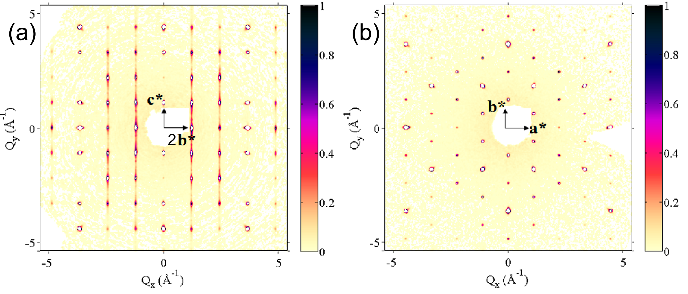
Single crystal X-ray diffraction data reported here were collected with molybdenum K– radiation () using an Agilent Supernova diffractometer equipped with an Atlas detector. We performed the data integration and cell refinement using the CrysAlis Pro Software, analyzed the structure by SIR-2011 in WinGX, and refined the data using the SHELXL 2014 software package [1, 2, 3, 4]. Visualisation of the crystal structure (Figure 1) was done in VESTA [5]. The observed diffraction pattern of a small single crystal, picked out of the polycrystalline batch used for our SR measurements, is fully consistent with the structural model of Ref. [6], whereby honeycomb layers of edge-sharing RuCl6 octahedra are vertically stacked with an offset along in a monoclinic crystal structure (spacegroup ). In the diffraction patterns, presented in Figure 2, diffuse scattering is visible in addition to sharp Bragg-reflections along with general selection rule and ( is integer) and (due to -centering). This diffuse scattering has been attributed to the occurrence of stacking faults [6], whereby a layer is in-plane shifted by . The associated energy cost is minimal as the Cl positions are unchanged upon such a shift. In the structural refinement of the sharp diffraction peaks we parameterize such stacking faults by allowing Ru atoms to partially occupy the honeycomb center site at the expense of the nominal Ru site .The results of the converged structural refinement at room temperature are shown in Table 1. The fractional site occupancies for the two Ru positions show that we roughly have about one stacking fault every six Ru layers.

| Compound | -RuCl3 | |||||
| Measurement temperature | K | |||||
| Crystal system | Monoclinic | |||||
| Space group | ||||||
| Unit cell dimensions | , , , | |||||
| , , Volumme | ||||||
| Z | 4 | |||||
| Density (calculated) | g/cm3 | |||||
| Reflections collected | ||||||
| Unique reflections | of which suppressed | |||||
| R(int) | ||||||
| R(sigma) | ||||||
| Goodness-of-fit | ||||||
| Final R indices (R) | ||||||
| wR | ||||||
| Wavelength | ||||||
| Weight scheme for | , | |||||
| the refinement | where | |||||
| Atomic Wyckoff-positions | Atom | Site | x | y | z | site occupancy |
| Ru | 4j | 0.50 | 0.33325 | 0 | 0.864 | |
| Ru | 2b | 0.50 | 0 | 0 | 0.13578 | |
| Cl | 8j | 0.2501 | 0.17107 | 0.76279 | 1 | |
| Cl | 4i | 0.2359 | 0 | 0.23865 | 1 | |
| Isotropic temperature factors () | , | |||||
| Anisotropic temperature factor () | , | |||||
| , | ||||||
| , | ||||||
| , | ||||||
| , | ||||||
| , | ||||||
| , | ||||||
II Cl– bond length estimate
Previous SR measurements involving compounds containing fluorine and oxygen [8] lead us to expect the formation of a Cl– bond in -RuCl3 with a bond length that can be estimated as follows. Using the known lengths for H–F (), H–Cl () and H–O () bonds and simply scaling, using the bond lengths of F– (–) [9] and O– () [9, 10], we obtain a likely Cl– bond length of roughly –.
III Dipole field calculations
We note that both Mu1 and Mu3 sites which we identified have six nearby Cl- ions, four of which are at the Wyckoff positions and two of which are at the Wyckoff positions. Consequently, if either Mu1 or Mu3 is indeed close to the correct muon stopping site we would expect two muon precession frequencies with an amplitude ratio of 2 : 1. This is roughly in line with what is observed with the two frequencies, but this would not explain why one frequency disappears at around 11 K. Consequently, we have explored some other possible scenarios.
III.1 Stacking faults
To study the effect of stacking faults at which the RuCl3 layers are translated by (see Ref. 6 for details), we calculated the dipolar field at our candidate muon sites assuming the presence of stacking faults. For these calculations, we chose the magnetic structure of Ref. [6] and assumed, following Ref. [11], that the moments lie at to the -axis in the plane. We calculated our results assuming that the muon site was somewhere between the sites identified by our electrostatic calculations and the nearest Cl- ion, parametrizing these sites by the distance along this line from – (we expect the likely site to be somewhere between these limits). In the presence of stacking faults, the symmetry between certain sites is broken, so that we needed to calculate the dipolar field for all the 8j and 4i sites close to our candidate sites. Our results are shown in Figure 3. The first column of panels shows the results without stacking faults, while subsequent columns show results with stacking faults at the -values indicated (note that the Ru planes lie at integer values of , and so we notionally indicate the stacking faults at half-integer values). These results demonstrate that stacking faults only have a significant effect on the precession signals if the muon is directly adjacent to the fault. For example Mu1, which is at , is affected by stacking faults at , whereas Mu3 and Mu4, which are at , are primarily affected by a stacking fault at . Thus, the effect of stacking faults on the muon precession signal is very local. Notice also that different symmetry-equivalent sites (which result in identical traces for the case without stacking faults) can become inequivalent when a stacking fault is nearby and this could be a source of broadening (because the slightly different frequencies will sum together to produce a damped signal).
III.2 Magnetization reversal at stacking faults
It is also possible that at a stacking fault the magnetic moments reverse in sign (this cannot be determined from the data in Ref. 6, but this scenario is possible given the change in exchange pathways at the fault). We have considered this possibility and repeated the above calculations for the case in which all magnetic moments are reversed () below the stacking fault. The corresponding calculations are shown in Figure 4. The results are quite similar, but there are noticeable differences when the fault is close to the muon, and in particular in this case Mu3 sites have lower precession signals while those at Mu2 are higher.
However, since the stacking faults only have a significant effect on the precession signals if the muon is very close by (in either case illustrated in Figure 3 or Figure 4), and since the distance between stacking faults may be of the order of 5–6 lattice planes (see [6] or Section I above), we conclude that our data are dominated by effects due to the fault-free structure.
III.3 In-plane order and three-dimensional order
In the magnetic structure proposed in Ref. 6 the spins in neighboring layers lie antiparallel. To examine the effect of in-plane order, but lack of order between the planes, we calculate the dipole fields at the candidate muon sites with different ordering configurations along the -axis. These are shown in Fig. 5. These results demonstrate that the precession signals at Mu1 are largely unaffected by lack of -axis order, though the greatest effect is when the magnetic configuration around the muon site is asymmetric with respect to a reflection about the plane . The precession signals corresponding to the other sites are more strongly affected.
III.4 AB stacking of Ru layers
An alternative stacking of the Ru layers in -RuCl3 has been proposed [7, 12] and a previous neutron scattering study attributed the two transitions observed to two different stacking orders [12]. Figure 6 summarizes the different structures and stackings proposed for -RuCl3. To investigate the feasibility of the AB stacking, which Banerjee et al. [12] highlight as the root for the higher temperature transition ( K) they observed, we performed DFT calculations for both the ABC and AB stacking orders shown in Figure 6 using the two pull potential all-electron codes WIEN2K [13] and FPLO [14, 15]. For these calculations we prepare an AB unit cell out of the ABC unit cell (see Figure 6) and keep the same atom positions without further structural relaxations. The total energy of the AB stacking turns out to be higher than the ABC stacking by a few tens of meV, making the AB stacking energetically less favorable. Additionally, we confirmed that the electrostatic potential predicts the muon site candidates to be unchanged in the AB stacking structure and calculated the dipole fields expected at these muon sites. The results, plotted in Figure 7, show that the Larmor precession frequencies of the muons are essentially the same as those we calculated for the structure. Therefore, it is unlikely that two different magnetic phases present in our sample due to the two proposed stacking orders (ABC and AB) is at the root of the two frequencies we observed in our SR experiment.

III.5 Alternative magnetic structure
A recent neutron diffraction study has proposed a magnetic structure in pristine single crystals of -RuCl3 with zig-zag antiferromagnetic ordering within the Ru layers but with 3-layer stacking periodicity [7]. Based on this magnetic structure we have calculated the dipole fields at the muon site candidates obtained from the earlier DFT analysis. Figure 8 presents the resulting muon precession frequencies for the muon site candidates in each of the three distinct layers of both the proposed spiral and collinear spin configurations. We note that the magnitudes of the frequencies are of the order of the observed ones and that a more realistic analysis including distortions of the muon sites towards the nearest Cl- ions could potentially improve the quantitative agreement. However, the spiral and collinear ordering lead to three and two distinct frequencies, respectively, associated with muons stopping near the three different Ru layers. Additionally, including the more realistic distortions towards nearby Cl- ions will in general lift the degeneracies of the frequencies associated with Cl- ions that are symmetry equivalent in the crystallographic unit cell but are not equivalent in the larger magnetic unit cell. Therefore, the number of precession frequencies we expect to observe experimentally in such a magnetic structure is larger than two. Hence, the 3-layer magnetic structure proposed by Cao et al. for single crystals is incompatible with our SR measurements of -RuCl3 powder. Nevertheless, another SR measurement on pristine -RuCl3 single crystals is required to confirm whether the 3-layer ordering is indeed the appropriate one and might provide important insights into the proposed change of magnetic structure induced by mechanical deformations of single crystals.
References
- [1] G. M. Sheldrick, Acta Crystallographica Section A Foundations of Crystallography 64, 112 (2008).
- [2] L. J. Farrugia, Journal of Applied Crystallography 45, 849 (2012).
- [3] M. C. Burla, R. Caliandro, M. Camalli, B. Carrozzini, G. L. Cascarano, C. Giacovazzo, M. Mallamo, A. Mazzone, G. Polidori, and R. Spagna, Journal of Applied Crystallography 45, 357 (2012).
- [4] G. M. Sheldrick, Acta Crystallographica Section C Structural Chemistry 71, 3 (2015).
- [5] K. Momma and F. Izumi, Journal of Applied Crystallography 41, 653 (2008).
- [6] R. D. Johnson, S. C. Williams, A. A. Haghighirad, J. Singleton, V. Zapf, P. Manuel, I. I. Mazin, Y. Li, H. O. Jeschke, R. Valentí, and R. Coldea, Physical Review B 92, 235119 (2015).
- [7] H. B. Cao, A. Banerjee, J. Q. Yan, C. A. Bridges, M. D. Lumsden, D. G. Mandrus, D. A. Tennant, B. C. Chakoumakos, and S. E. Nagler, (2016), arXiv:1602.08112 .
- [8] J. S. Möller, P. Bonfà, D. Ceresoli, F. Bernardini, S. J. Blundell, T. Lancaster, R. De Renzi, N. Marzari, I. Watanabe, S. Sulaiman, and M. I. Mohamed-Ibrahim, Physica Scripta , 068510 (2013a).
- [9] J. Möller, D. Ceresoli, T. Lancaster, N. Marzari, and S. Blundell, Physical Review B 87, 121108 (2013b).
- [10] F. R. Foronda, F. Lang, J. S. Möller, T. Lancaster, A. T. Boothroyd, F. L. Pratt, S. R. Giblin, D. Prabhakaran, and S. J. Blundell, Physical Review Letters 114, 017602 (2015).
- [11] S. M. Winter, Y. Li, H. O. Jeschke, and R. Valenti, (2016), arXiv:1603.02548 .
- [12] A. Banerjee, C. A. Bridges, J.-Q. Yan, A. A. Aczel, L. Li, M. B. Stone, G. E. Granroth, M. D. Lumsden, Y. Yiu, J. Knolle, S. Bhattacharjee, D. L. Kovrizhin, R. Moessner, D. A. Tennant, D. G. Mandrus, and S. E. Nagler, Nature Materials (2016), 10.1038/nmat4604.
- [13] P. Blaha, K. Schwarz, D. Madsen, G. K. H.and Kvasnicka, and J. Luitz, WIEN2k, An Augmented Plane Wave + Local Orbitals Program for Calculating Crystal Properties (Karlheinz Schwarz, Techn. Universität Wien, Austria, 2001).
- [14] K. Koepernik and H. Eschrig, Phys. Rev. B 59, 1743 (1999).
- [15] I. Opahle, K. Koepernik, and H. Eschrig, Phys. Rev. B 60, 14035 (1999).
- [16] I. Pollini, Physical Review B 50, 2095 (1994).