Plasmonic Purcell factor and coupling efficiency to surface plasmons. Implications for addressing and controlling optical nanosources
Abstract
The Purcell factor is a key quantity in cavity quantum electrodynamics (cQED) that quantifies the coupling rate between a dipolar emitter and a cavity mode. Its simple form unravels the possible strategies to enhance and control light-matter interaction. Practically, efficient light-matter interaction is achieved thanks to either i) high quality factor at the basis of cQED or ii) low modal volume at the basis of nanophotonics and plasmonics. In the last decade, strong efforts have been done to derive a plasmonic Purcell factor in order to transpose cQED concepts to the nanocale, in a scale-law approach. In this work, we discuss the plasmonic Purcell factor for both delocalized (SPP) and localized (LSP) surface-plasmon-polaritons and briefly summarize the expected applications for nanophotonics. On the basis of the SPP resonance shape (Lorentzian or Fano profile), we derive closed form expression for the coupling rate to delocalized plasmons. The quality factor factor and modal confinement of both SPP and LSP are quantified, demonstrating their strongly subwavelength behaviour.
1 Introduction
Nanophotonics permits light-matter interaction at the nanoscale, down to the single photon/single atom level. The motivations are notably sensitive sensing with applications such as nano-optical imaging (surface analysis), environnemental health (air pollutants, infectious agents detection), security (explosive detection) or healthcare (cancer early diagnosis, theranostics) and the miniaturization of photonics components for on chip integrated ultrafast devices. The optical cross-section is a simple way to characterize the efficiency of light-matter interaction. For a molecule, it is typically , that has to be compared to the focus area of a diffraction limited beam, of the order of in the visible domain. This unsuitability between the light confinement and the active size of the molecule points out the difficulty of so-called nanoscopy [1]. In the last decades, several strategies have been proposed to increase the efficiency of light-matter interaction. i) Increasing the absorption cross-section by working at low temperature; indeed, in the limit of very low temperature (), the molecular absorption cross-section increases up to the diffraction limit revealing that the molecule absorbs almost all the incoming light of a focused beam [2, 3]. ii) Increasing the duration of the interaction by placing the molecule inside an optical microcavity presenting a high quality factor [4]. iii) Confining the excitation beam below the diffraction limit thanks to near-field optics [5, 6, 7, 8, 9] or plasmonics [10, 11].
Quantitatively, the efficiency of light-matter interaction can be inferred from the so-called cooperativity parameter . The meaning of this parameter is easily understood from a classical point of view [12, 13]. In free-space, the cooperativity can be expressed as the ratio between the resonant atomic cross-section and the effective area of a gaussian beam with a beam waist ; . Therefore, the cooperativity quantifies the suitability between the focused spot and the molecule active area. In an optical Fabry-Perot cavity, it increases to where is the finesse of the cavity. The cavity enhances the free-space cooperativity by the number of wave round trips inside the cavity and an additionnal factor of four accounting for the intensity enhancement at a mode antinode. In cavity quantum electrodynamics (cQED), the cooperativity writes for a single atom
| (1) |
where is the coupling rate between the atom and the cavity mode. and refers to the cavity losses rate and the atom decay rate in vacuum, respectively ( is the decay rate in the homogeneous medium of optical index ). The strong coupling regime, () leads to a reversible energy exchange between the cavity and the atom. In the weak coupling regime, the cavity opens a new channel for the atom (irreversible) relaxation with a decay rate . The Purcell factor quantifies the effect of the cavity on the atom decay rate and writes
| (2) |
with the modification of the decay due to the optical microcavity. It also expresses [14]
| (3) |
where is the quality factor of the cavity and the effective volume of the cavity mode involved in the coupling. is the emission wavelength of the atom. This expression is equivalent to the classical description with the finesse for a Fabry-Perot cavity.
Remarkably, the Purcell factor expression (3) points out that spontaneous emission can be efficiently controlled in an optical cavity presenting a high quality factor and/or a strongly confined mode. However, high Q cavities are obtained at the price of low modal (diffraction limited) confinement [4]. In this context, molecular plasmonics proposes a new strategy for light–matter interaction [15, 16, 17]. The strong confinement of surface plasmon polaritons insures efficient coupling at a deeply subwavelength scale whereas cavity-QED increases the duration of interaction. At this point, we have to mention that the factor entering the Purcell factor is the lower of the cavity factor and the atomic resonance. Actually, where and are the quality factor of the atom emission spectrum and cavity, respectively [18]. That is why cQED generally works at low temperature where atomic resonance is sufficiently narrow so that cavity modifies the spontaneous emission ( and ). On the contrary, low Q factor of plasmon resonance permits to work at room temperature and let envision high-speed optical devices [19, 20]. This paves the way to ultrafast control at the nanoscale.
The Purcell factor describes the emitter-cavity coupling as a function of the optical cavity properties, independently of the emitter properties. Particularly, the best coupling efficiency is achieved for high ratio, that occurs either for a narrow resonance, or a deeply confined mode. The Purcell factor is therefore a key parameter to transpose cQED concepts to quantum plasmonics [15, 21, 22, 23, 24, 25, 26, 27, 28].
In this article, we first summarize the derivation of the Purcell factor in an optical microcavity with particular attention to the underlying hypothesis (section 2). In section 3, we briefly discuss some expected applications of efficient emitter-SPP coupling. Then we study the concept of plasmonic Purcell factor. Since the mode confinement is the crucial parameter for achieving a high Purcell factor near a plasmonic nanostructures, we follow a progression from extended metal film (section 4) and plasmonic waveguide (section 5) supporting delocalized surface plasmon polaritons (SPP) towards nanoparticles sustaining localized surface plasmons (LSP, section 6).
2 Purcell Factor
2.1 Purcell factor in an optical microcavity ; generalities
The spontaneous emission at the angular frequency from the excited state to the ground state of an excited atom presents a decay rate that follows Fermi’s golden rule
| (4) |
is the interaction hamitonian describing the coupling of an atom to an electromagnetic field within the dipolar approximation, taken at the position of the atom. The operators and refer to the atomic transition dipole moment and the electric field, respectively. In the following, we are interested in the effect of the cavity on the spontaneous emission rate. Therefore, we separate the decay rate into the free-space contribution (in an homogeneous medium of optical index ) and the cavity contribution
| (5) | |||||
| (6) | |||||
| (7) |
In addition, we assume a single-mode cavity, resonant at , therefore
| (8) |
indicates a photon into the cavity mode. The coupling rate between the atom and the cavity mode (see Eq. 1) obeys . The electric-field operator associated to the single-mode cavity writes [12, 29]
| (9) |
where is the quantization volume, the boson operator and describes the spatial variations of the mode into the cavity [ at a node and at an antinode]. To achieve this expression, the classical electric field is expressed
| (10) |
and is normalized with respect to the energy
| (11) | |||||
| (12) |
where we assumed a non dispersive medium. Finally, the mode volume obeys
| (13) |
Spectral shape of the resonance
In the case of a lossy cavity, the dirac distribution in (8) is replaced by the density of modes per unit angular frequency (unit: ). Moreover, the profile of the mode resonance is assumed to be Lorentzian
| (14) |
Defining the resonance quality factor , we can rewrite
| (15) |
Spatial profile
Inserting the electric field operator (Eq. 9) into the interaction hamiltonian, we achieve
| (16) |
where we introduced the dipole moment orientation (i.e ).
Purcell factor
2.1.1 Summarize
The cavity contribution to the decay rate obeys
| (19) | |||||
where is the so-called Purcell factor, reveals the position dependency (from cancellation at a node to maximum effect at an antinode) and the denominator factor shows the effect of the detuning between the emission frequency and the cavity resonance. Finally, the emitter couples to modes presenting a polarisation along the dipole moment [quantified by the term .
In the following, we are interested in defining the Purcell factor for a dipolar emitter coupled to a plasmonic nanostructure. It is therefore useful to recall the hypothesis done to demonstrate the Purcell factor expression (3):
- •
the Purcell factor is associated to a given mode of the cavity
- •
the cavity resonance follows a Lorentzian shape
- •
the mode volume can be estimated from expression (13), assuming a non dispersive medium. It equivalently writes
(20) where is the electric field associated to the cavity mode [ describes the mode profile].
2.1.2 Purcell factor near a nanofiber
The full control of spontaneous emission in 3D optical cavity is a technological challenge and is bandwidth limited so that simpler configurations have been proposed. In particular, fluorescence emission into photonic nanowires can be enhanced over a large spectrum range so that it has been widely studied in the last decade [30, 31]. To derive the Purcell factor near a waveguide, we define an arbitrary quantization length . The electric-field operator and the density of mode write, respectively [32]
| (21) | |||||
| (22) | |||||
| (23) |
defines the mode effective area and is the group velocity of the guided mode. is the density of guided modes. We then proceed as previously and the Purcell factor for the guided mode simplifies to
| (24) |
The Purcell factor near a photonic nanofiber is governed by the group index of the guided mode and its transverse confinement . High Purcell factor necessitates low group velocity (e.g. near the band-edge of the dispersion relation [33, 34]) and/or a highly confined mode.
2.1.3 Purcell factor in a Fabry-Pérot cavity
We finally consider the one-dimensional (1D) planar waveguide. The density of guided modes obeys where refers to the mode effective index. The Purcell factor becomes
| (25) | |||||
| (26) |
is the mode effective length and characterizes its confinement.
2.1.4 Coupling efficiency (-factor)
So far, we have introduced the Purcell factor that quantifies the coupling strength between a dipolar emitter and a photonic structure. Since the emitter could relax to its ground state thanks to various channels (cavity mode, leakage, non radiative energy transfer), it is also useful to define the coupling efficiency to the cavity mode. It is the so-called -factor
| (27) |
where is the total decay rate that includes all the relaxation channels. In a single mode cavity, the relaxation channels are generally the cavity mode with the decay rate , and coupling to leaky modes. Usually, leakage are of the same order of magnitude than the initial radiative rate () so that . For instance, a Purcell factor of about corresponds to a coupling efficiency . High factor is required for low threshold lasering [35].
2.2 Decay rate near lossy and dispersive materials
In presence of a lossy and dispersive medium, the modification of the decay rate can be described either within classical Lorentz model of an oscillating dipole [36, 37, 38] or within the full quantum description [39]. In both cases, this leads to the following expression for the rate modification
| (28) |
where is the Green’s tensor associated to the emitter surroundings and refers to its diagonal components along the dipolar direction . This expression quantifies the modification of the decay rate in a complex surroundings and will be our starting point to determine the effect of plasmonic nanostructures on the fluorescence decay rate. The expression (28) is a generalization of the Fermi’s golden rule to dispersive and lossy surroundings. Indeed, the Fermi’s golden rule (4) can be recast in the form
| (29) | |||||
| (30) | |||||
| (31) |
where we introduced the coupling strength and density of modes , as discussed above. It is well-known from scattering formalism that the partial local density of states (P-LDOS) is related to the Green’s dyad (unit: ) [38, 40]
| (32) |
so that Eq. (28) and (4) are fully equivalent in a non-absorbing medium. The P-LDOS also writes from cQED considerations
| (33) |
Therefore, the P-LDOS grasps the spatial dependency of the coupling to the cavity mode by and the density of available modes for light emission , per unit angular frequency and unit volume.
3 Plasmonic addressing and control of optical nanosources
Before discussing the plasmonic Purcell factor, it is worthwile to briefly introduce some expected applications of coupled emitter-SPP configurations. We indicate here the main applications and refer the reader to the literature for more complete descriptions.
3.1 Surface enhanced spectroscopies
Surface Enhanced Raman Spectroscopy (SERS) is probably among the first application of molecular material coupled to plasmonics nanostructures [41] and is now available at the single molecule level [42] so that ultrasensitive chemical or biosensors are expected [43]. In the context of Purcell factor, we would like to mention that the SERS efficiency follows a law with the LSP properties [44].
Following SERS, metal enhanced fluorescence (MEF) leads to enhancement factor of the order of tens [45, 46, 47, 48, 49, 50] with possible applications to nanotheranostics [51, 52]. The fluorescence increase results from excitation field enhancement and emission rate modification (Purcell effect). However, due to the non radiative energy transfer to metal nanostructures, it is crucial to distinguish the radiative from non radiative rates. At the end, the critical parameter is the quantum yield of the emitter so that the total enhancement is generally limited by the intrinsic quantum yield of the fluorescent molecule [53, 54, 55, 56]. Remarkably, coupling an emitter to a plasmonic nanostructures opens the way to the control of the photophysical processes [57], notably blinking effect [58, 59, 60] and photobleaching [61], but also to modify the ratio between magnetic and electric allowed dipolar transitions [62, 63].
3.2 Nano-optical antennas
Since a plasmonics nanostructure efficiently interfaces a single molecule to far-field radiation [64, 65, 66, 67] the concept of optical nano-antenna has emerged since a decade [68, 69, 70]. Optical nano-antennas rely on plasmonics nanostructures to efficiently redirect the fluorescence emission and cQED-like description gives an insight of the coupling mechanism [15, 71]. Recently, a Purcell factor up to 1000 keeping a reasonable quantum yield and with a collection efficiency of 84% was demonstrated [72]. Moreover, optical nano-antenna could efficiently interface molecular fluorescent emission and a nanophotonic waveguide [73] with possible applications to realize a platform for quantum optics. In addition, coupling a single photon source to an optical nano-antenna permits to control its emission cadency [74, 75, 76, 77, 78, 79, 80, 81, 82, 83]. Realization of indistiguishable single photons is also a major issue [84, 85].
3.3 SPP amplification and SPASER
Taking advantage of the analogy between optical microcavities and plasmonic nanostructures, the concepts of plasmon nanolaser and amplifier were proposed [86, 87, 88]. It consists of a gain medium in contact to a metal nanostructure so that stimulated emission of plasmon occurs. The efficiency of the stimulated emission strongly depends on the Purcell factor [89, 90, 91, 92].
3.4 Dipole-dipole coupling
4 Quantum emitter decay rate near a metal mirror
4.1 Thick mirror

Figure 1 presents the dipolar total decay rate as a function of the distance to a gold surface [103]. The perfect mirror (perfect electric conductor - PEC) case is also shown for comparison [104]. Far from the surface, we observe a typical interference pattern since the driving reflected field has to be in phase with the dipolar oscillation to enhance the emission rate. When the emitter touches the surface, the decay rate presents a finite value for the perfect mirror. It fully cancels for a dipole parallel to the surface (Fig. 1a) whereas it doubles for a perpendicular dipole (Fig. 1b), in agreement with the image dipole induced into the conductor. In case of real metal, the behavior is rather different close to the surface due to the apparition of new decay channels such as excitation of SPP and non radiative energy transfer to the metal film[100, 101].

4.1.1 Relaxation channels
The various contributions to the total decay rate are easily determined from the Sommerfeld expansion of the dipolar emission, represented in Fig. 2 [101, 103]. Indeed, since the metal/air interface is invariant along , it is possible to expand the Green’s dyad over the wavenumber so that the total decay rate (Eq. 28) obeys (see also A.1)
| (34) | |||||
| (35) |
where represents the orientation of the emitter and is the distance to the metal surface. is the power radiated by the oscillating dipole in vacuum. is the dipolar emission power spectrum (in the -space) and represents the dipolar emission at a surface wavector . is , normalized with respect to (unit of : meter).
It is useful to distinguish the radiative waves for which that contributes to the radiative rate and the evanescent waves . Evanescent waves corresponds to either SPP or lossy waves (LSW) [100, 101]. Particular attention has to be paid to SPP contribution, shown in Fig. 2b. It presents a Lorentzian profile that permits to derive a closed form expression for the Purcell factor as we will discuss in details later. Finally, the large wavectors are associated to electron scattering losses. These so called lossy waves are responsible for fluorescence inhibition close to the metal surface. Let us mention that an additional non radiative energy transfer, namely electron-hole pair creation in the metal, could also occur at very short separation distances () but is not included in this model since it involves non local description of the metal dielectric constant[100].

Eventually, we present in Fig. 3 the radiative, SPP and lossy waves contribution to the total decay rate. The radiative decay rate is the main channel for large separation distances whereas lossy waves dominate very close to the metal surface. The SPP contribution is practically negligible for a parallel dipole (Fig. 3a) since Au/air SPP is TM polarized (that is the electric field is perpendicular to the metal surface), hence low factor (Fig. 3c). At the opposite, we observe that a perpendicular dipole is efficiently coupled to a SPP (Fig. 3b). About 90% of the dipolar emission couples to the Au/air SPP for a separation distance of , see Fig. 3c. This high -factor originates from a low radiative rate due to a destructive interference between the direct and reflected dipolar fields (Fig. 3b). At shorter distances where the SPP rate is higher, we achieve for , see Fig. 3c.
At this point, a closed form expression of the plasmonic Purcell factor is achievable. Since the emitted power follows a Lorentzian profile near the SPP resonance, the integration over the SPP contribution leads to [105]
| (36) |
This extends the Purcell factor definition to a (lossy) SPP. Care has to be taken when interpretating plasmonic Purcell factor, in particular the role of losses. We derive in A.2 the SPP contribution assuming a lossless metal. It perfectly matches the SPP contribution calculated for a real lossy metal (see green dots in Fig. 3b). So the plasmonic Purcell factor does not depend on the propagation length [105, 106], although it explicitly appears in the denominator of expression (36). Mathematically, the integral of the Lorentzian resonance gives the number of supported modes and does not depend on ohmic losses [107]. This is finally not surprising since SPP rate defines the coupling efficiency to the propagating SPP, no matter of how energy is dissipated afterward.

As a consequence, the Purcell factor as well as the coupling efficiency to a SPP can be high, even in presence of strong losses. We plot in Fig. 4 the different contributions to the decay rate at . Due to strong losses in gold, it is difficult to separate the SPP and LSW contributions to the total decay rate. This behaviour is discussed in detail in A.3. For simplicity, we estimate the SPP decay rate from the emitter power integrated over . All decay channels present a behaviour very similar to the case (compare with Fig. 3). Although we expect strong losses in the metal due to interband transitions, we still observe for , see Fig. 4b. The SPP has an effective index (effective wavelength ) but an extremelly short propagation length . Therefore, the SPP presents only a single spatial oscillation over its propagation length. This quasi-mode, although efficiently excited would not be of interest for the control of a dipolar emission.

So far, we only discussed the emission process of the dipolar emitter. Another quantity of interest is the collection efficiency. We plot in figure 5 the scattering rate , defined as the dipolar power dissipated in the far-field zone. The difference with the radiative rate is due to absorption in the metal but doesn’t depend on the distance to the metal surface [103] (see also A.4). We observe in Fig. 5b that absorption becomes negligible above .

As last quantity, we plot in Fig. 6 the collection efficiency as a function of the detection numerical aperture (NA). refers to the power scattered in a given NA. A NA=0.6 air objectif collects 10% of the emitted signal so that strategies has to be developed to improve this efficiency such as surface plasmon coupled emission (SPCE) [46] or grating decoupler [108, 109, 110].
4.1.2 Quality factor and mode confinement
Micro-optical cavities are generally characterized by their mode confinement and quality factor. For comparison purposes, it is therefore convenient to estimate also SPP confinement and quality factor.
Firstly, the SPP quality factor is estimated from the resonance Lorentzian profile (Fig. 3b). At it comes .
Secondly, we would like to characterize the mode confinement. For this purpose, we identify the SPP rate (Eq. 36) to the Purcell factor (Eq. 25). Remembering the hypothesis done to achieve the Purcell factor expression, we calculate at the gold/air interface where the SPP field amplitude is the highest and sum the contributions for dipoles along the three directions (so that ). Indeed, the decay rate obeys then
| (37) | |||
| (38) |
We estimate the SPP effective and group indices and , respectively, from the dispersion relation. From identification to the Purcell factor (Eq. 38), we can attribute the effective length to the gold/air SPP (Purcell factor of ). This effective length is similar to the SPP penetration depth in air . Indeed, neglecting the mode extension in gold, its effective length can be estimated as (assuming the validity of this expression in presence of the absorbing and dispersive gold mirror)
| (39) |
and is a good parameter to estimate the SPP confinement.
For , we achieve and (and ). However, plasmonic Purcell factor is menaningless in this spectral range as pointed out in the previous section.
4.2 Thin metal film
4.2.1 Relaxation channels

We now turn to the thin metal film case. We consider a 50 nm gold film deposited on a glass substrate, and an emission wavelength . The Au/air and Au/glass SPP modes couple and to form a leaky and a bound SPP. We determine their characteristics using the reflection pole method [111]. The leaky mode is confined at the gold/air interface and has an effective index and a propagation length (). The bound SPP is confined at the gold/glass interface (, corresponding to ).
Figure 7a presents the dipolar emitted power . We observe a similar behaviour than above a gold mirror with three different contributions; the radiative waves (), the two SPP contributions and the lossy waves for high wavenumbers . Note that the leaky plasmon also contributes to the radiative waves via leakage into the glass substrate (so-called surface plasmon coupled emission -SPCE) [112]. We again observe the strong increase of LSW for a dipolar emitter close to the metal film. Finally, the two peaks near and reveal the SPP contributions. Their resonance profiles are shown in details on Fig. 7(b,c). These two modes result from the coupling of the (leaky) Au/air and (bound) Au/glass SPP of a single interface. Therefore their resonant behaviour does not follow a Lorentzian profile anymore but rather a Fano profile [113, 114]. Fano profile expresses
| (40) | |||
| (41) |
This expression is a generalization of the Fano formula to lossy materials according to ref. [114]. is the ratio between the optical response of the mode of interest and the second mode and introduces an offset due to losses. The Fano fits perfectly match the two SPP resonances (Fig. 7b). The leaky mode presents a high parameter () so that it closely follows a Lorentzian profile. However, the bound mode resonance cannot be fitted with a Lorentzian profile since it is coupled to a leaky mode that can be treated as a continuum, hence the Fano behaviour [18].

The SPP contribution is therefore estimated from the integral of the Fano resonance. If we remove the continuum background contribution, we obtain (see B)
| (42) | |||||
We plot in Fig. 8(a,b), the different contributions to the total decay rate for a dipolar emitter oriented parallel or perpendicular to the metal surface. The radiative rate refers to the power integrated over (radiative waves in medium 1). Note that leakages of SPP1 into the substrate contribute to the scattering rate but not to the radiative rate. We discuss this point later. The contribution of surface plasmon to the decay rate remains small for a dipole parallel to the surface. Differently, for a perpendicular dipole, we observe strong excitation of the gold/air SPP1 (Fig. 8b) whereas the gold/glass SPP2 contribution remains small due to poor overlap with the dipolar emission since the emitter is located in air. This is quantified by the coupling efficiency represented on Fig. 8(c,d). Up to coupling efficiency is achieved for a vertical dipole above the gold film. This high -factor originates from the small radiative rate at this distance due to an interference effect between the direct emission and the reflected field. Note that the SPP rate is equal to the free-space rate at this distance (). Therefore the power coupled into the SPP guide is the same as the power emitted in the whole space ( str) by an isolated radiator.
Since the gold/air SPP is leaky into the substrate (), it is worthwhile to estimate leakage radiation that are of interest for e.g. leakage radiation microscopy [92, 115, 116] or surface enhanced fluorescence [45, 117]. In order to determine the leakage contribution, we first estimate the leakage and Ohmic losses of the gold/air SPP. Indeed, the finite propagation length of the leaky plasmon originates from i) intrinsic (Ohmic) losses with the rate per unit length and ii) radiative losses into the substrate with the rate per unit length [116, 118]. The propagation length expresses
| (43) |
The leakage rate is estimated by cancelling the ohmic losses [ put to zero] to . Therefore SPP leakage contributes for to the SPP rate. Figure 9a presents the power emitted in the far field as well as the radiative rate and SPP leakage (). We also estimate the absorption in the metal . Only a small part of the radiative emission is absorbed in the metal and doesn’t contribute to the far-field emission. This rate practically doesn’t depend on the distance to the metal film as in the mirror case (see Fig. 5). Last, the collection efficiency into the substrate using an oil immersion objective () is estimated as and is shown in Fig. 9b. It reaches at 200 nm.

4.2.2 Quality factor and mode confinement
We proceed as previously (see §4.1.2) to estimate the SPPs quality factor and effective length. We gather the values achieved for the leaky and bound SPPs in table 1. Although the leaky SPP is delocalized into the substrate, we can estimate an effective length according to the Purcell factor definition. It is again close to the penetration depth in air, indicating that the confinement entering the Purcell factor corresponds to the near-field behaviour of the SPP mode. We will observe a similar behaviour for localized surface plasmons (see §6.2).
| (nm) | (nm) | ||||
|---|---|---|---|---|---|
| leaky | 85 | 159 | 193 | 0.92 | 3.02 |
| bound | 57 | 27 | 76 | 0.57 | 5.1 |
4.3 In-plane plasmonic cavity
SPP is a surface wave, intrinsically confined near the metal film. It can be furthermore laterally confined by distributed Bragg reflectors, forming an in-plane plasmonic cavity as schemed in Fig. 10 [119, 120, 121]. Such an open in-plane plasmonic cavity would further increase the plasmonic Purcell factor, with the possibility to access the fluorescent emitter. This enables an external control or manipulation of the emitter position (optical trapping, AFM manipulation, …) or emission properties (Stark effect using a STM tip, …).
The two-dimensional dipolar emission can be numerically achieved using the 2D-Green’s dyad technique. It expresses [105, 122]
| (44) |
where is the emitter position in the transverse plane and the component of the wavector along the invariant axis. Since the 2D-Green’s dyad associated to the grating structure can be numerically computed, we can define the normalized dipolar emission power as a function of the propagation constant . This makes a direct analogy between the dipolar emission in 1D and 2D geometries and all the above discussion near a flat metal film is easily extended to this configuration.
Figure 10 compares the behaviour of a (2D) planar plasmonic cavity and a (1D) Fabry-Perot cavity. The 2D dipolar emission and 1D dipolar emission are calculated for a dipolar emitter parallel to the mirrors and located at the center of the cavity. The dipolar emission significantly increases for cavity size with an integer and the mode effective wavelength ( or in the plasmonic and Fabry-Perot cavities, respectively). This corresponds to the emission into the even modes of the cavity that presents an antinode at the cavity center. We observe a cut-off for cavity size below . The normalized decay rate, calculated as a function of the cavity size, presents very similar behaviour for these two cavities. This demonstrates the strong analogy between the in-plane plasmonic cavity and the micro-optical cavity. However, some distinct features appear in the planar cavity. First, since SPP are polarized perpendicular to the metal film, we do not observe polarization degeneracy (TE/TM) in the planar cavity. We also note the permanent contribution of the planar SPP mode at . The gold/glass SPP at contribution is very weak (not shown). Finally, a planar plasmonic cavity relies on the confinement of the SPP surface waves instead of confining a bulk mode for an optical micro-cavity. This additionnal mode confinement leads to a significant increase of the decay rate inside the cavity [121]. This is however at the price of strong losses.

5 Purcell factor near a plasmonic waveguide
As discussed above, SPP Purcell factor into extended metal film can be increased by an in-plane cavity that confines laterally the delocalized SPP. However, the lateral confinement is still limited to about . Stronger lateral mode confinement can be achieved in plasmonic waveguides. For instance, metal nanowires does not present a cut-off and the lateral mode confinement is not diffraction limited but given by the nanowire cross-section [123]. Therefore, we expect high coupling efficiency of a dipolar emitter to a metal nanowire [124, 125, 126, 127, 128, 129, 130]. Metal nanowires define 1D plasmonic waveguides with a great potential for integrated optical routing [131]. They can be chemically synthesized with high crystallinity hence supporting SPP with reduced losses [132, 133, 134, 135, 136]. SPP propagation can be controlled by a single emitter, leading to the concept of single photon transistor [137]. Reciprocally, two distant emitters can be interfaced via surface plasmons, with applications such as SPP mediated resonant energy transfer [94, 122], remote qubits entanglement [99, 138] or nano-optical logical gates [98]. SPP gain amplification has also been shown when dipolar emitters play the role of gain medium [139, 140, 141].
On the basis of expression (44) the different decay channels near a plasmonic waveguide are easily estimated. In order to specifically discuss the contributions of the guided modes, we rewrite the expression (44) in the equivalent form
| (45) |
where we have introduced the 2D-LDOS [105, 122]
| (46) |
and is the difference between the total Green’s tensor of the 2D-structure and the free-space Green’s tensor . It describes the role of the waveguiding structure only.

Figure 11a represents the variation of the 2D-LDOS near a silver nanowire as a function of the propagation constant . It behaves very similarly to the mirror case (Fig. 2). In particular, we can again distinguish three contributions to the decay rate. i) Radiative waves for , ii) SPP peaked near the plasmon propagation constant (here ) and iii) lossy waves at large . The corresponding decay channels are calculated by numerical integrations over the different wave domains.
We first discuss the SPP rate. The SPP contribution follows a Lorentzian profile as above a thick plasmon film. It is peaked on the plasmon propagation constant and with a FWHM inversely proportional to the propagation length (; see the inset of figure 11a). This again leads to a closed form expression of the plasmonic Purcell factor [105, 122]
| (47) | |||||
It is worth to compare this expression to the lossless case for which the coupling rate to the guided mode expresses [142, 143]
| (48) |
where is the electromagnetic field associated with the guided SPP mode. For a circular waveguide, an analytical expression is readily obtained (see supplementary information of ref. [122]). Figure 11b compares the SPP rate obtained using the 2D-LDOS formalism in the lossy nanowire (eq. 74) and the lossless ideal system (eq. 48). Lossy and lossless rates perfectly superimpose, revealing that the coupling rate to the guided mode does not depend on the propagation losses [105].
The equivalence between the lossy and lossless Purcell factors for a guided mode can be understood as follows. The dispersion relation governs the guided mode excited by an emitter near the emission angular frequency . Therefore, the dirac distribution in the decay rate Eq. (8) becomes
| (49) |
introducing the group velocity and assuming a weak dispersion around the emission wavelength. The dirac distribution is again replaced by a Lorenzian profile for a lossy waveguide so that we achieve
| (50) |
Moreover, the quality factor and effective volume of the guided mode are expressed, respectively by
| (51) |
and
| (52) | |||||
| (53) |
defines the mode effective area (see Eq. 22) and we assume again a non dispersive medium. Finally, the Purcell factor simplifies to the nanofiber expression (24)
| (54) |
and does not depend on the propagation length. Moreover, the guided SPP mode volume obeys that becomes strongly confined for short propagation distances . It makes a bridge between delocalized and localized SPP, notably in the quasi-static regime where they present very similar behaviour [122]. This discussion also points out that the role of losses in the plasmonic Purcell factor must be carried out carefully.
Eventually, the Purcell factor is identical considering a real lossy or an ideal non-lossy plasmonics waveguide, so that we can identify the Purcell factor expressions (24) and (48) to estimate the SPP confinement. As previously, we identify at the nanowire surface,
| (55) | |||
| (56) |
The effective surface of the guided SPP is shown on Fig. 11c as a function of the wire radius. This reveals that quantum plasmonics relies on strongly subwavelength mode confinement with huge Purcell factor (up to see inset of Fig. 11c) [21, 144]. We achieve similar values for and a gold nanowire (not shown). The small SPP effective area permits to decrease the threshold for SPP amplification compared to a photonic nanowire of similar cross-section [145].

Finally, the radiative and non radiative contributions are presented in Fig. 11(d,e). Above nm, the only contribution to the non radiative rate is SPP, due to losses along the propagation. At short distances, electron scattering are responsible of the additionnal losses, leading to fluorescence quenching. Last, a coupling efficiency into the guided plasmon of is achieved at 20 nm from the nanowire (not shown) [105].
For a nanowire above a glass substrate, the guided SPP becomes leaky. The 2D-LDOS again follows a Fano profile (or a Lorentzian profile for weak leakage) and the leakage rate is easily estimated as done in the case of thin metal film. For instance, of the emission is collected into the substrate for a 100 nm silver wire 50 nm above the glass substrate [105].
Since the 2D-Green’s dyad associated to a plasmonic waveguide can be numerically computed, this formalism can be applied to arbitrary geometries [107, 146, 147, 148]. Specifically, crystalline silver nanowires present a pentagonal cross-section shape leading to strong mode confinement at the corners (see Fig. 12) [134, 149]. This mode confinement significantly increases the Purcell factor near the edge of the nanowire compared to a circular nanowire [105].
6 Localized plasmon
This last section is devoted to localized plasmon for which we expect full 3D subwavelength confinement. For the sake of clarity, we focus on a spherical metal nanoparticle (MNP) that constitutes a canonical configuration for LSP. We first consider the quasi-static approximation for which we derive analytical expressions for the mode volume and quality factor of each mode (§6.1). In section 6.2, we extend the discussion to the retarded regime using Mie theory.
6.1 Quasi-static regime
6.1.1 Dipolar LSP
Let us consider a spherical metal nanoparticle (MNP) of radius small compared to the wavelength. For clarity, we first discuss the dipolar response of the particle. It is characterized by the effective polarizability
| (57) | |||
| (58) |
The so-called radiative reaction () originates from finite size effect and energy conservation considerations [150, 151, 152, 153]. is the nanoparticle quasi-static (dipolar) polarisability and is the metal dielectric constant. The dipole plasmon resonance appears at such that . In case of Drude metal, the dipolar resonance is with the bulk metal plasma angular frequency.
If the metal dielectric constant obeys a Drude model, the effective polarizability follows a Lorentzian profile near the LSP resonance [154]
| (59) | |||||
| (60) | |||||
| (61) |
is the decay rate of the particle dipolar mode, and includes both the Joule () and radiative [] losses rates. We can therefore define the quality factor of the dipolar mode that typically ranges from 10 to 25 for gold or silver nanoparticles [151].
The decay rate of a dipolar emitter located in the very near-field of a spherical metal particle approximates to [155, 154, 156]
| (62) | |||||
| (63) | |||||
| (64) |
for a dipole emitter oriented perpendicular or parallel to the nanoparticle surface and an emission tuned to the dipolar particle resonance (). In order to determine the dipolar mode effective volume, we now identify the coupling rate to the Purcell factor (Eq. 3). It is worthwile to note that the Purcell factor is obtained assuming a single mode cavity. Since the dipolar mode is three-fold degenerated, the SPP rate writes so that we can identify the Purcell factor to the SPP rate of a randomly oriented dipolar emitter at the particle surface (). The average decay rate writes
| (65) |
where we define the dipolar LSP mode volume . is the volume of the MNP. As a consequence, although the dipolar LSP is radiative in the far-field, it is possible to assign a finite mode volume within the quasi-static approximation. As expected, it is strongly subwavelength for small MNP [69, 151, 157, 158].
6.1.2 High order modes
The Purcell factor associated to the dipolar mode can be generalized to each LSP mode. Due to the (2n+1) degeneracy, the coupling rate to the mode (n=1, dipolar LSP, n=2, quadrupolar LSP, ...) obeys 11 1 We use a different definition for the mode volume in Ref. [151], assuming a randomly oriented dipole. The definition used here, that includes the mode degeneracy is more consistent with usual Purcell factor definition.
| (66) | |||||
| (67) | |||||
| (68) | |||||
| (69) | |||||
| (70) |
The quality factor is governed by ohmic losses in the MNP, identical for all the modes, and radiative losses that slightly decreases for high order modes []. Quality factor therefore slightly increases from a few 10 for a dipolar LSP () to about 50 to 100 for high order modes. In addition, the high order modes are more confined than the dipolar LSP (, , ). This quantifies the mode confinement and reveals that although having low Q factor, LSP presents sub diffraction mode volume that ensures efficient coupling to a nearby emitter at the origin of surface enhanced spectroscopies.
Last, we can again define a coupling efficiency -factor to a given mode. It strongly depends on the distance to the MNP but also of the emission wavelength. For an emission wavelength matching the dipolar LSP, the coupling efficiency reaches into the n=1 mode at a distance nm. It can be as high as into the quadrupolar mode at nm if the wavelength emission matches the n=2 LSP resonance (not shown, see ref. [151]).
6.1.3 Energy confinement
In cQED, the mode volume is defined as the energy confinement (see eq. 20). For dispersive materials, this extrapolates to
| (71) | |||
where () is the electromagnetic field of the mode. In the quasi-static regime, the magnetic contribution is negligible and the electric field is confined near the particle surface. This definition then leads to [159]. The effective volumes of the (2n+1) degenerated LSP modes are represented on Fig. 13 (see C for details). We observe that the (2n+1) degenerated modes present the same volume (note that the energy confinement of the (l,m) mode is normalized with respect to the (l,m=0) mode maximum intensity).

The ratio between the mode volume deduced from Purcell factor () and the mode volume estimated from energy mode confinement assuming a lossless metal ( )
| (72) |
depends on the mode number only. We attribute this difference to the (Joule and radiative) losses that are neglected in the energy confinement but taken into account in the Purcell volume derivation. Unlike delocalized SPP for which Purcell factor does not depend on Joule losses, Purcell factor for a localized LSP is strongly affected by losses in the metal. In addition, we observe that both Purcell and energy confinement derivations leads to identical values for the dipolar mode volume. This again shows that the mode volume entering in the Purcell factor is governed by the mode near-field behaviour, even for a leaky mode (see also §4.2.2). In addition, it is worth noticing that the LSP volume derived from the Purcell factor, taking into account losses, does not depends on the losses in the quasi-static approximation. As for cQED, the effect of losses on the Purcell factor are fully included in the quality factor (Eq. 68).
6.2 Retarded regime
So far, we have discussed the Purcell factor within the quasi-static regime. In this section, we generalize it to spherical MNP of arbitrary size using Mie expansion. Particular attention is again devoted to the definition of the mode volume as the energy confinement, in analogy with cQED definition. Dipolar emission near a spherical particle of arbitrary size is exactly solved using Mie (modal) expansion [160]. We can therefore again define a mode volume by identifying the contribution to the total decay rate of the mode to the Purcell expression (3)[161]. In the following, we define this volume as the Purcell effective volume. We compare it to the mode energy confinement (see eq. 71). However, the application of definition (71) is difficult in the retarded regime since LSPs leak in the far-field. As far as light-matter coupling is concerned, the pertinent parameter is the confinement of the mode energy stored inside the cavity. Following the work of Koenderink [162], the intrinsic mode volume is estimated from the energy confinement, excluding radiative leaks [i.e, ordinate at the origin in Fig. 14(a,b)].
In figure 14, we compare the mode volume estimated from Purcell factor and energy definition as a function of the MNP size. This again reveals sub diffraction mode volume ensuring efficient light-matter interaction. For small particle, we recover the quasi-static limit. For large particles, the energy definition is in qualitative agreement with the Purcell factor definition. However, large MNP supports quasi-mode with lifetime shorter than the collective oscillation so that the concept of Purcell factor fails to describe this regime.

6.3 Generalisation of the Purcell factor concept
6.3.1 Complex mode volume
Recently, Sauvan and coworkers define a complex mode volume [164]
| (73) |
where () is the quasi-normal mode. The convergency of the volume integral is ensured thanks to phase matching layers. This generalises the Purcell factor to dissipative cavities such that
| (74) |
This definition is consistent with the Purcell volume definition (Fig. 14) and reconciles the Purcell factor with the energy-like confinement definition of the mode volume [165, 166]. Similar definitions should work for the effective mode area or length.
Moreover, detuning between the emission wavelength and the mode resonance leads to a Fano-like behaviour [164, 167]. Taking into account the (2n+1) LSPs degeneracy, the decay rate for a randomly oriented emitter obeys
| (75) |
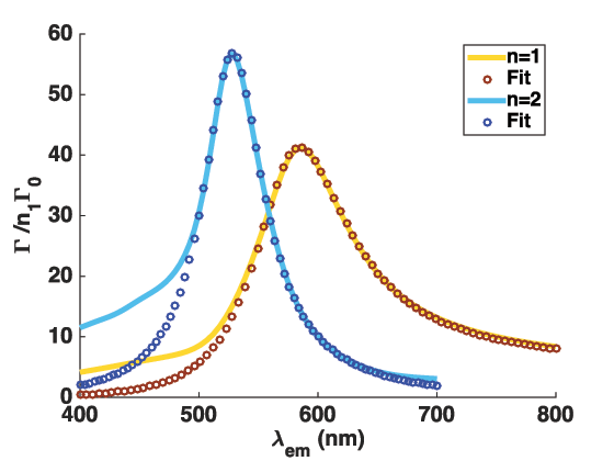
and generalizes expression (19) to lossy cavities. Figure 15 presents the dipolar and quadrupolar LSP contributions to the decay rate near a gold MNP. We observe an excellent agreement with the Fano-like behaviour. From the fitting parameters, we extract the Purcell factor, quality factor and effective volume of the dipolar mode: , and respectively. Similarly, for the quadrupolar mode: , and .
6.3.2 Decay channels

The Purcell factor quantifies the coupling efficiency into a given LSP mode but does not distinguish radiative from Joule losses, as for delocalized SPPs. Figure 16a presents the radiative and non radiative contributions to the decay rate near a gold MNP. At very short distances, the decay rate is enhanced by several orders of magnitude. For distances below a few nanometers, the non local response of the metal permittivitty (not included in this work) could lead to different values [168, 169, 170] but without significative change in the behaviour. In the very near-field, the main coupling mechanism is non-radiative energy transfer, responsible for fluorescence quenching [171]. Above nm, the total decay rate is still enhanced by a factor of about ten but is mainly radiative. In Fig. 16b, we show the contribution of the dipolar, quadrupolar and high order LSP mode to the total decay rate. At short distances, high order modes play a dominant role since they are strongly confined near the particle surface, as revealed by their extremelly small effective volume (Fig. 14) [55, 151, 156, 172]. For distances of a few tens of nanometer, the radiative dipolar mode is responsible for the decay rate enhancement. This is summarized in Fig. 16c where the coupling efficiency to the dipolar mode reaches at nm. The apparent quantum yield is governed by the dipolar mode in the near-field of the MNP as revealed by the two superimposed curve in Fig. 16c.
7 Conclusion
In this work, we transposed the cQED Purcell factor to plasmonics. The Purcell factor characterizes the capability of a structure to modify and control the emission of a nearby emitter. Both optical cavity and plasmon modes present high Purcell factors that favor efficient excitation by a dipolar emitter. However it originates from high quality factors in case of optical cavities (but diffraction limited confinements) and on strongly subwavelength confinements for plasmonics (but low quality factors). Therefore the Purcell factor reveals the new paradigm opened by quantum plasmonics for achieving efficient light-matter interaction at the nanoscale. This permits a scale law approach profiting from the strong maturity of cQED concepts and adapt them to nanophotonics. We also discussed the presence of losses that are inevitable at the nanoscale. The Purcell factor includes Ohmic losses that are inherent to the excitation of plasmon in real metal so that it has to be manipulated with care. In the particular case of plasmonic waveguides, the coupling efficiency to a guided mode is not affected by propagation losses. Obviously, only low loss systems such that crystalline nanowires or nanoplatelets would permit realistics applications. Finally, hybrid plasmonic/nanophotonic configurations would profit from the concept of Purcell factor through a common description of the coupling mechanism.
7.1 Acknowledgments
The research leading to these results has received funding from the Agence Nationale de la Recherche (grants QDOTICS ANR-12-BS-008 and PLACORE ANR-13-BS10-0007), and the Conseil Régional de Bourgogne (PARI ACTION PHOTCOM).
Appendix A Decay rate above a flat mirror
A.1 Green’s tensor and total decay rate
The Green’s tensor above a mirror writes where is the Green’s tensor of the infinite homegeneous medium of optical index and describes the reflection on the mirror. It can be expressed thanks to Weyl expansion
| (76) | |||
and, writing in cylindrical coordinates ;
() refer to the fresnel reflexion coefficient on the slab for TE (TM) polarized light and are the cylindrical Bessel function.
A.2 SPP contribution near a lossless mirror
In this section, we consider a metal()/dielectric() single interface, and assume a lossless metal [. The coefficient of reflexion writes
| (79) |
and presents a pole for leading to the (real) SPP wavector
| (80) |
The dipolar emission power spectrum near the SPP resonance can be assessed from an expansion of near its pole
| (81) |
so that the SPP contribution to the decay rate is determined from the residu. We achieve [100]
| (82) | |||
A.3 SPP contribution near a strongly lossy mirror
We now consider the strongly lossy configuration at the emission wavelength . Figure 17a presents the dipolar emitter spectrum as a function of the in-plane wavector. Due to strong losses in the metal, lossy wave cannot be separated from the SPP resonance (compare to Fig. 2). Indeed, the power spectrum presents a very broad resonance-like power spectrum at high . Therefore the dipolar emitter can couple to either the SPP or LSW, hence a Fano behaviour. In order to determine the SPP contribution to the total decay rate, we numerically integrate the emitted power in the range (continuous line in Fig. 17c). We also estimate the SPP behaviour assuming a Fano resonance as described in the next section (dots in Fig. 17c). Finally, the SPP contribution assuming a lossless metal and the total decay rate are also represented. We observe that the lossless model overestimates the SPP rate and could be even larger than the total decay rate (around nm). The SPP rate estimated from Fano profile or by direct numerical integration are in qualitative agreement but show some discrepencies, illustrating the diffculty to separate the SPP and LSW contributions.

A.4 Scattering rate
The scattering rate is achieved from the power scattering in the far-field zone. It can be estimated from asymptotic behaviour of the Green’s tensor. We achieve
where the differential scattering cross-section expresses
| (83) | |||||
| (84) |
above the film, for a dipole parallel or perpendicular to the surface, respectively and,
| (85) | |||||
| (86) |
in the substrate. and refer to the Fresnel transmission coefficients for p and s polarized light, respectively. This generalises the expression achieved for a thick mirror [103] to a finite metal slab or multilayer system. The difference betwen the radiative and scattering rates originates from the part of the radiative waves absorbed before achieving the far-field (see e.g. Fig. 5) and/or from SPCE leakage (see Fig. 9).
Appendix B Fano profile
Assuming a Fano profile of the emitted power (see e.g. Fig. 1b), it follows [114]
| (87) | |||||
| (88) | |||||
| with | (89) |
where we note the losses rate of the SPP.
The SPP rate is then estimated from the integral of the emitted power. We first estimate the integral of the Fano resonance (the term removes the background contribution)
| (90) | |||||
| (91) | |||||
| (92) |
and the SPP rate simplifies to
| (93) | |||||
| (94) | |||||
| (95) |
so that we recover the expression (36) for a Lorentzian profile ().
Appendix C Energy confinement of LSPs
The electrostatic potential associated to the LSP mode of a spherical MNP follows [150]
| (96) | |||
| (97) |
with the normalisation constant
| (98) |
and is the associated Legendre polynomial. The boundary conditions imposes
| (99) |
that fixes the resonances of the LSP. If the dielectric constant of the metal follows a Drude behaviour, the resonance angular frequency obeys . The LSP presents a degeneracy and the electric field of the (n,m) mode writes
The effective volume is expressed extrapolating the cQED description to a dispersive medium
| (108) | |||||
Note that,since the mode is degenerated, we normalized the field with respect to maximum of the field considering all the degenerated modes ( and not ( in the denominator of Eq. 108). Assuming a lossless Drude metal, it comes
| (109) |
so that the effective volume is for m=0 [159]
| (110) |
For , the integration over is numerically evaluated (see Fig. 13). We note a discrepancy between the mode volume deduced from Purcell factor () and the mode volume estimated from energy mode confinement assuming a lossless metal ( ). Indeed, we have [151]
so that the ratio
| (111) |
depends on the mode number only.
References
- [1] Hell S W 2007 Science 316 1153
- [2] Celebrano M, Kukura P, Renn A and Sandoghdar V 2011 Nature Photonics 5 95–98
- [3] Tamarat P, Maali A, Lounis B and Orrit M 2000 The Journal of Physical Chemistry A 104 1–16
- [4] Vahala K J 2003 Nature 424 839–846
- [5] Betzig E and Chichester R J 1993 Science 262 1422–1425
- [6] Veerman J A, Garcia-Parajo M F, Kuipers L and van Hulst N F 1999 J. of Microscopy 194 477–482
- [7] Sick B, Hecht B, Wild U P and Novotny L 2001 Journal of Microscopy 202 365–373
- [8] Molenda D, Colas des Francs G, Fischer U, Rau N and Naber A 2005 Optics Express 13 10688
- [9] Wenger J and Rigneault H 2010 International Journal of Molecular Science 11 206–221
- [10] Brun M, Drezet A, Mariette H, Chevalier N, Woehl J C and Huant S 2003 Europhys. Lett. 64 634–640
- [11] Bharadwaj P, Anger P and Novotny L 2007 18 044017
- [12] Grynberg G, Aspect A and Fabre C 2010 Quantum optics (Paris: Cambridge University Press)
- [13] Tanji-Suzuki H, Leroux I, Schleier-Smith M, Cetina M, Grier A, Simon J and Vuletic V 2011 Advances in Atomic, Molecular, and Optical Physics 60 201–240
- [14] Purcell E 1946 Physical Review 69 681
- [15] Agio M 2012 Nanoscale 4 692–706
- [16] Sandoghdar V, Agio M, Chen X, Gotzinger S and Lee K 2012 Antennas, quantum optics and near-field microscopy (Cambrid)
- [17] Lodahl P, Mahmoodian S and Stobbe S 2015 Review of Modern Physics 87 347–400
- [18] van Exter M P, Nienhuis G and Woerdman J P 96 Physical Review A 54 3553–3558
- [19] Brinks D, Castro-Lopeza M, Hildner R and van Hulst N 2013 PNAS
- [20] Elvira D, Braive R, Beaudoin G, Sagnes I, Hugonin J, Abram I, Robert-Philip, Lalanne P and Beveratos A 2013 Applied Physics Letters 103 061113
- [21] Chang D, Sörensen A, Hemmer P and Lukin M 2006 Physical Review Letters 97 053002
- [22] Waks E and Sridharan D 2010 Physical Review A 82 043845
- [23] Buckley S, Rivoire K and Vuckovic J 2012 Report on Progress in Physics 75 126503
- [24] Hümmer T, García-Vidal F J, Martín-Moreno L and Zueco D 2013 Physical Review B 87 115419
- [25] Tame M S, McEnery K R, Ozdemir S K, Lee J, Maier S A and Kim M S 2013 Nature Physics 9 329–340
- [26] Hakami J, Wang L and Zubairy M 2014 Physical Review A 89 053835
- [27] Törmä P and Barnes W 2015 Rep. Prog. Phys. 78 013901
- [28] Rousseaux B, Dzsotjan D, Colas des Francs G, Jauslin H, Couteau C and Guérin S 2015 submitted
- [29] Gérard J M 2003 Topics Appl. Phys. 90 269–315
- [30] Yalla R, Kien F L, Morinaga M and Hakuta K 2012 Physical Review Letters 109 063602
- [31] Claudon J, Gregersen N, Lalanne P and Gerard J M 2013 ChemPhysChem 14 2393–2402
- [32] Jun Y 2010 Plasmonic control of light emission: tailoring light emission properties with metal nanostructures Ph.D. thesis Stanford University
- [33] Woldeyohannes M and John S 2003 J. Opt. B: Quantum Semiclass. Opt. 5 R43–R82
- [34] Chen Y N, Chen G Y, Chuu D S and Brandes T 2009 Physical Review A 79 033815
- [35] Nomura M, Iwamoto S, Kumagai N and Arakawa Y 2008 Physica E 40 1800–1803
- [36] Metiu H 1984 Surface enhanced spectroscopy Progress in Surface Science vol 17 ed Prigogine I and Rice S A (New York: Pergamon Press) pp 153–320
- [37] Girard C, Martin O J F and Dereux A 1995 Physical Review Letters 75 3098–3111
- [38] Colas des Francs G, Girard C and Dereux A 2002 Journal of Chemical Physics 117 4659–4666
- [39] Knoll L, Scheel S and Welsch D 2001 Coherence and Statistics of Photons and Atoms (John Wiley & Sons, Inc.) chap QED in dispersing and absorbing media
- [40] de Vries P, van Coeverden D V and Lagendijk A 1998 Review of Modern Physics 70 447–466
- [41] Moskovits M 2005 Journal of Raman Spectroscopy 36 485–496
- [42] Ru E L and Etchegoin P 2012 Annu. Rev. Phys. Chem. 63 65–87
- [43] Ru E L and Etchegoin P 2008 Principles of surface-enhanced Raman spectroscopy and related plasmonic effects (Elsevier Science)
- [44] Maier S 2006 Optics Express 14 1957–1964
- [45] Fort E and Grésillon S 2008 Journal of Physics D: Applied Physics 41 013001
- [46] Lakowicz J R 2005 Analytical Biochemistry 337 171–194
- [47] Kühn S, Hakanson U, Rogobete L and Sandoghdar V 2006 Phys. Rev. Lett. 97 017402
- [48] Anger P, Bharadwaj P and Novotny L 2006 Phys. Rev. Lett. 96 113002
- [49] Viste P, Plain J, Jaffiol R, Vial A, Adam P M and Royer P 2010 ACS Nano 4 759–764
- [50] Derom S, Berthelot A, Pillonnet A, Benamara O, Jurdyc A, Girard C and Colas des Francs G 2013 Nanotechnology 24 495704
- [51] Loo C, Lin A, Hirsch L, Lee M H, Barton J, Halas N, West J and Drezek R 2004 Technol. Cancer. Res. T. 3 33–40
- [52] Wang L S, Chuang M C and Ho J A A 2012 International Journal of Nanomedicine 7 4679–4695
- [53] Brokmann X, Coolen L, Dahan M and Hermier J P 2004 Physical Review Letters 93 107403
- [54] Buchler B C, Kalkbrenner T, Hettich C and Sandoghdar V 2005 Physical Review Letters 95 63004
- [55] Mertens H, Koenderink A and Polman A 2007 Physical Review B 76 115123
- [56] Carminati R, Caze A, Cao D, Peragut F, Krachmalnicoff V, Pierrat R and Wilde Y D 2015 Surface Science Reports 70 1–41
- [57] Girard C, Martin O, Lévêque G, Colas des Francs G and Dereux A 2005 Chemical Physics Letters 404 44
- [58] Stefani F D, Vasilev K, Bocchio N, Gaul F, Pomozzi A and Kreiter M 2007 New J. Phys. 9 21
- [59] Fu Y, Zhang J and Lakowicz J R 2007 447 96–100
- [60] Ji B, Giovanelli E, Habert B, Spinicelli P, Nasilowski M, Xu X, Lequeux N, Hugonin J P, Marquier F, Greffet J and Dubertret B 2015 Nature Nanotechnology 10 170–175
- [61] Cang H, YLiu, Wang Y, Yin X and Zhang X 13 Nano Lett. 2013 5949–5953
- [62] Karaveli S and Zia R 2011 Physical Review Letters 106 193004
- [63] Taminiau T, Karaveli S, van Hulst N and Zia R 2012 Nature Communications 3 979
- [64] Mühlschlegel P, Eisler H J, Martin O J F, Hecht B and Pohl D W 2005 Science 308 1607 – 1609
- [65] Taminiau T H, Segerink F B and van Hulst N F 2007 IEEE Transactions on antennas and propagation 55 3010–3017
- [66] Huang C, Bouhelier A, Colas des Francs G, Bruyant A, Guénot A, Finot E, Weeber J C and Dereux A 2008 Physical Review B 78 155407
- [67] Bonod N, Devilez A, Rolly B, Bidault S and Stout B 2010 Physical Review B 82 115429
- [68] Bharadwaj P, Deutsch B and Novotny L 2009 Adv. Opt. Phot. 1 438–483
- [69] Greffet J J, Laroche M and Marquier F 2010 Physical Review Letters 105 117701
- [70] Krasnok A, Slobozhanyuk A, Simovski C, Tretyakov S, Poddubny A, Miroshnichenko A, Kivshar Y and Belov P 2015 Scientific Reports 5 12956
- [71] Delga A, Feist J, Bravo-Abad J and Garcia-Vidal F J 2014 Physical Review Letters 112 253601
- [72] Akselrod G, Argyropoulos C, Hoang T, Ciraci C, CFang, Huang J, Smith D and Mikkelsen M 2014 Nature Photonics 8 835–840
- [73] Arango F B, Kwadrin A and Koenderink A 2012 ACS Nano 6 10156–10167
- [74] Schietinger S, Barth M, Aichele T and Benson O 2009 Nano Letters 9 1694–1698
- [75] Marty R, Arbouet A, Paillard V, Girard C and Colas des Francs G 2010 Physical Review B 82 081403(R)
- [76] Mallek-Zouari I, Buil S, Quelin X, Mahler B, Dubertret B and Hermier J P 2010 Applied Physics Letters 97 053109
- [77] Celebrano M, Lettow R, Kukura P, Agio M, Renn A, Gotzinger S and Sandoghdar V 2010 Optics Expres 18 13829–13835
- [78] Cuche A, Mollet O, Drezet A and Huant S 2010 Nano Letters 10 4566–4570
- [79] Busson M P, Rolly B, Stout B, Bonod N and Bidault S 2012 Nature Communications 3 962
- [80] Mollet O, Huant S, Dantelle G, Gacoin T and Drezet A 2012 Phys. Rev. B 86 045401
- [81] Gu Y, Wang L, Ren P, Zhang J, Zhang T, Martin O J F and Gong Q 2012 NanoL 12 2488–2493
- [82] Filter R, Slowik K, Straubel J, Lederer F and Rockstuhl C 2014 Optics Letters 39 1246–1249
- [83] Nerkararyan K and Bozhevolnyi S 2014 Optics Letters 39 1617–1620
- [84] Beveratos A, Gerard I A A and Robert-Philip I 2014 The European Physical Journal D 68 377
- [85] Grange T, Hornecker G, Hunger D, Poizat J, Gerard J, Senellart P and Auffeves A 2015 Physical Review Letters 114 193601
- [86] Bergman D J and Stockman M I 2003 Physical Review Letters 90 027402
- [87] Protsenko I E, Uskov A V, Zaimidoroga O A, Samoilov V N and O’Reilly E 2005 Physical Review A 71 063812
- [88] Berini P and Leon I D 2012 Nature Photonics 6 16–24
- [89] Winter G, Wedge S and Barnes W L 2006 New Journal of Physics 8 125
- [90] De Leon I and Berini P 2008 Physical Review B 78 161401
- [91] Colas des Francs G, Bramant P, Grandidier J, Bouhelier A, Weeber J C and Dereux A 2010 Optics Express 18 16327–16334
- [92] Grandidier J, Colas des Francs G, Massenot S, Bouhelier A, Weeber J C, Markey L and Dereux A 2010 Journal of Microscopy 239 167–172
- [93] Andrew P and Barnes W L 2000 Science 290 785–788
- [94] Martin-Cano D, Martin-Moreno L, Garcia-Vidal F and Moreno E 2010 Nano Letters 10 3129–3134
- [95] Gonzaga-Galeana J and Zurita-Sanchez J 2013 The journal of physical chemistry 139 244302
- [96] Karanikolas V, Marocico C and Bradley A L 2014 Physical Review A 89 063817
- [97] Bouchet D, Cao D, Carminati R, Wilde Y D and Krachmalnicoff V 2015 arxiv 1507.04235
- [98] Dzsotjan D, Sorensen A S and Fleischhauer M 2010 Physical Review B 82 075427
- [99] Gonzalez-Tudela A, Martin-Cano D, Moreno E, Martin-Moreno L, Tejedor C and Garcia-Vidal F J 2011 Physical Review Letters 106 020501
- [100] Ford G W and Weber W H 1984 Physics Reports 113 195–287
- [101] Barnes W 1998 Journal of Modern Optics 45 661–699
- [102] Johnson P and Christy R 1972 Physical Review B 6 4370–4379
- [103] Chance R R, Prock A and Silbey R 1975 62 2245–2253
- [104] Hinds E 1991 Advances in atomic, molecular, and optical physics 28 237–289
- [105] Barthes J, Colas des Francs G, Bouhelier A, Weeber J C and Dereux A 2011 Physical Review B (Brief Reports) 84 073403
- [106] Siahpoush V, Sondergaard T and Jung J 2012 Physical Review B 85 075035
- [107] Colas des Francs G, Grandidier J, Massenot S, Bouhelier A, Weeber J C and Dereux A 2009 Physical Review B 80 115419
- [108] Aouani H, Mahboub O, Bonod N, Devaux E, Popov E, Rigneault H, Ebbesen T and Wenger J 2011 Nano Letters 11 637–644
- [109] Choy J T, Bulu I, Hausmann B M, Janitz E, Huang I C and Loncãr M 2013 Applied Physics Letters 103 161101
- [110] Kumar A, Weeber J C, Bouhelier A, Eloi F, Buil S, Quelin X, Nasilowski M, Dubertret B, Hermier J and Colas des Francs G 2015 Scientific Reports 5 16796
- [111] Anemogiannis E, Glytsis E N and Gaylord T K 1999 Journal of Lightwave Technology 17 929–941
- [112] Mollet O, Huant S, Dantelle G, Gacoin T and Drezet A 2012 Phys. Rev. B 86 045401
- [113] Miroshnichenko A E, Flach S and Kivshar Y S 2010 Review of Modern Physics 82 2257–2298
- [114] Gallinet B and Martin O 2011 Physical Review B 83 235427
- [115] Drezet A, Hohenau A, Koller D, Stepanov A, Ditlbacher H, Steinberger B, Aussenegg F, Leitner A and Krenn J 2008 Materials Science and Engineering B 149 220–229
- [116] Bouhelier A, Colas des Francs G and Grandidier J 2012 Plasmonics, From Basics to Advanced Topics (Springer Series in Optical Sciences vol 167) (Springer) chap Surface plasmon imaging, pp 225–268
- [117] Lakowicz J R 2005 Analytical Biochemistry 337 171–194
- [118] Raether H 1986 Surface Plasmons on Smooth and Rough Surfaces and on Gratings (Springer Verlag)
- [119] Weeber J C, Bouhelier A, Colas des Francs G, Markey L and Dereux A 2007 Nanoletters 7 1352
- [120] Gonga Y and Vuckovic J 2007 Applied Physics Letters 90 033113
- [121] Derom S, Bouhelier A, Kumar A, Leray A, Weeber J C, Buil S, Quelin X, Hermier J and G Colas des Francs 2014 Physical Review B 89 035401
- [122] Barthes J, Bouhelier A, Dereux A and Colas des Francs G 2013 Scientific Reports 3 2734
- [123] Takahara J, Yamagishi S, Taki H, Morimoto A and Kobayashi T 1997 Optics Letters 22 22 475–477
- [124] Chang D, Sörensen A, Hemmer P and Lukin M 2007 Physical Review B 76 35420
- [125] Kolesov R, Grotz B, Balasubramanian G, Stöhr R J, Nicolet A A L, Hemmer P R, Jelezko F and Wrachtrup J 2009 Nature Physics 5 470–474
- [126] Huck A, Kumar S, Shakoor A and Andersen U L 2009 Physical Review Letters 106 096801
- [127] Gruber C, Kusar P, Hohenau A and Krenn J R 2012 Applied Physics Letters 100 221102
- [128] Ropp C, Cummins Z, Nah S, Fourkas J T, Shapiro B and Waks E 2013 Nature Communications 4 1447
- [129] Bermudez-Urena E, Gonzalez-Ballestero C, Geiselmann M, Marty R, Radko I, Holmgaard T A, Alaverdyan Y, Moreno E, Garcia-Vidal F, Bozhevolnyi S and Quidant R 2015 Nature Communications 6 7883
- [130] Kress S, Antolinez F, Richner P, Jayanti S, Kim D, Prins F, Riedinger A, Fischer M, Meyer S, McPeak K, Poulikakos D and Norris D 2015 NanoLetters ASAP
- [131] Wei H and Xu H 2012 Nanophotonics 1 155–169
- [132] Ditlbacher H, Hohenau A, Wagner D, Kreibig U, Rogers M, Hofer F, Aussenegg F R and Krenn J R 2005 Physical Review Letters 95 257403
- [133] Laroche T, Vial A and Roussey M 2007 Applied Physics Letters 91 123101
- [134] Song M, Bramant P, Bouhelier A, Sharma J, Dujardin E, Zhang D and Colas des Francs G 2011 ACS Nano 5 5874–5880
- [135] Viarbitskaya S, Teulle A, Cuche A, Sharma J, Girard C, Dujardin E and Arbouet A 2013 Applied Physics Letters 103 131112
- [136] Viarbitskaya S, Teulle A, Marty R, Sharma J, Girard C, Arbouet A A and Dujardin E 2013 Nature Materials 12 426–432
- [137] Chang D, Sörensen A, Demler E and Lukin M 2007 Nature Physics 3 807–812
- [138] Chen G Y, Lamber N, Chou C H, Chen Y N and Nori F 2011 Physical Review B 84 045310
- [139] Grandidier J, Colas des Francs G, Massenot S, Bouhelier A, Markey L, Weeber J, Finot C and Dereux A 2009 Nano Letters 9 2935–2939
- [140] Kéna-Cohen S, Stavrinou P, Bradley D and Maier S 2013 Nano Letters 13 1323–1329
- [141] Paul A, Zhen Y R, Wang Y, Chang W S, Xia Y, Nordlander P and Link S 2014 NanoLetters 14 3628–3633
- [142] Snyder A and Love J 1983 Optical Waveguide Theory (Chapman & Hall)
- [143] Chen Y, Nielsen T R, Gregersen N, Lodahl P and Mork J 2010 Physical Review B 81 125431
- [144] Russell K, Yeung K and Hu E 2012 Physical Review B 85 245245
- [145] Oulton R, Sorger V, Zentgraf T, Ma R, Gladden C, Dai L, Bartal G and Zhang X 2009 Nature 461 629–632
- [146] Paulus M, Gay-Balmaz P and Martin O 2001 Physical Review E 63 66615
- [147] Kottmann J P, Martin O J F, Smith D S and Schultz S 2001 Journal of Microscopy 202 60–65
- [148] Colas des Francs G, Hugonin J P and Čtyroký J 2011 Optical and Quantum Electronics (Proc. OWTNM10) 42 557–570
- [149] Nauert S, Paul A, Zhen Y R, Solis D, Vigderman L, Chang W S, Zubarev E R, Nordlander P and Link S 2014 ACS Nano 8 572–580
- [150] Jackson J 1998 Classical electrodynamics 3rd ed (Hoboken: John Wiley & Sons)
- [151] Colas des Francs G 2009 International Journal of Molecular Science 10 3931–3936
- [152] Ru E L, Somerville W and Auguié B 2013 Physical Review 87 012504
- [153] Grigoriev V, Bonod N, Wenger J and Stout B 2015 ACS Photonics 2 263
- [154] Carminati R, Greffet J, Henkel C and Vigoureux J 2006 Optics Communications 261 368–375
- [155] Colas des Francs G, Girard C, Juan M and Dereux A 2005 Journal of Chemical Physics 123 174709
- [156] Colas des Francs G, Bouhelier A, Finot E, Weeber J C, Dereux A, CGirard and Dujardin E 2008 Optics Express 16 17654– 17666
- [157] Deeb C, Bachelot R, Plain J, Baudrion A L, Jradi S, Bouhelier A, Soppera O, Kain J, Huang L, Ecoffet C, Balian L and Royer P 2010 ACS Nano 4 4579–4586
- [158] Zhou X, Deeb C, Vincent R, Lerond T, Adam P M, Plain J, Wiederrecht G P, , Charra F, Fiorini C, Colas des Francs G, Soppera O and Bachelot R 2014 Applied Physics Letters 104 023114
- [159] Khurgin J B and Sun G 2009 J. Opt. Soc. Am. B 26 B83–B95
- [160] Kim Y S, Leung P T and George T F 1988 Surface Science 195 1–14
- [161] Colas des Francs G, Derom S, Vincent R, Bouhelier A and Dereux A 2012 International Journal of Optics 2012 175162
- [162] Koenderink A F 2010 Optics Letters 35 4208–4210
- [163] Derom S, Vincent R, Bouhelier A and Colas des Francs G 2012 Europhysics Letters 98 47008
- [164] Sauvan C, Hugonin J P, Maksymov I S and Lalanne P 2013 Physical Review Letters 110 237401
- [165] Zambrana-Puyalto X and Bonod N 2015 Physical Review B 91 195422
- [166] Kristensen P, Ge R C and Hughes S 2015 arxiv arxiv:1501.05938v1
- [167] M J Y, Perrin M and Lalanne P 2015 Physical Review X 5 021008
- [168] Leung P T 1990 Phys. Rev. B 42 7622
- [169] Castanie E, Boffety M and Carminati R 2010 Optics Letters 35 291–293
- [170] Girard C, Cuche A, Dujardin E, Arbouet A and Mlayah A 2015 Optics Letter 40 2116–2119
- [171] Anger P, Bharadwaj P and Novotny L 2006 96 113002
- [172] Kim J, Song J H, Jeong K Y, Ee H S and Seo M K 2015 Opt. Express 9 11080–11091