A novel 4D fast track finding system using precise space and time information of the hit
Abstract
We propose a novel fast track finding system capable of reconstructing four dimensional particle trajectories in real time using precise space and time information of the hits. Recent developments in silicon pixel detectors achieved time resolution and intense R&D is in progress to improve the timing performance, aiming at . The use of the precise space and time information allows the suppression of background hits not compatible with the time of passage of the particle and the determination of its time evolution. The fast track finding device that we are proposing is based on a massively parallel algorithm implemented in commercial field-programmable gate array using a pipelined architecture. We describe the algorithm and its implementation for a tracking system prototype based on 8 planes of silicon sensors used as a case study. According to simulations the suppression of noise hits is effective in reducing fake track combinations and improving real-time track reconstruction in presence of background hits. The system provides offline-like tracks with sub-microsecond latency and it is capable to determine the time of the track with picosecond resolution assuming 10 ps resolution for the hits.
keywords
Charged particle tracking; real-time system, silicon detectors1 Introduction
Recent developments in silicon pixel detectors achieved very good space and time resolutions, i.e. the GigaTracker [1] of the NA62 experiment at the Super Proton Synchrotron at CERN achieved resolutions of and for space and time, respectively. Studies on silicon 3D pixel sensors showed that a time resolution of can be obtained [2] . In addition intense R&D for fast timing detectors is in progress and sensors with improved time resolution are foreseen to be available for applications in experiments in the next years. A few examples are represented by microchannel plates PMTs [3] aiming at a resolution of about and and ultra fast silicon detectors [4] aiming to achieve time resolution of 10 ps and space resolution of 10 m.
The precise time information of the hits can be used to suppress noise hits not compatible with the expected time of passage of the particles. This feature would allow to use another dimension for discriminating signal and background events, particularly important for future experiments at high luminosities. The high luminosity phase of LHC (HL-LHC) is set to start after 2025 and aims to increase the total number of collisions by a factor 10 with a foreseen instantaneous luminosity of . At the HL-LHC an integrated luminosity of will be reached and a large number of proton-proton interactions will be produced at each bunch crossing, on average about primary interactions. This effect is indicated as pile-up. As a consequence detectors will be exposed to a higher level of radiation with huge data rates produced. Present trigger solutions adopted by LHC experiments would not be capable to reduce data rates without a significant loss of information and physics potential. A viable solution to overcome part of these problems is to include the tracking information in the early stages of the trigger chain. At high luminosity the pile-up becomes very important and association of tracks to different primary vertexes is more difficult. The use of fast-timing detectors can help in identifying tracks from different proton-proton interactions mitigating the pile-up effects.
Fast track finding systems with low level trigger capabilities have been proved to be crucial for high energy physics experiments at hadron colliders, e.g. the silicon vertex trigger of CDF experiment [5], and similar solutions are currently adopted by the ATLAS experiment [6]. Major upgrades are foreseen for the HL-LHC phase of the CMS experiment, especially in the design of the new silicon tracker and detector readout, in order to use the tracking information for first level trigger decisions [7].
In this work we propose a novel 4D real time tracking system using the precise space and time information of the hits that can be used for the low level trigger and we show how it improves the background rejection and the tracking performance in presence of noise hits.
2 4D artificial retina algorithm
The artificial retina algorithm for fast track reconstruction is described in Ref. [8] and it is inspired by neurobiology. Cellular units distributed in the space of track parameters are tuned to identify specific charged particle trajectories and provide response on how well a set of hits is matched to specific track hypotheses.
For simplicity sake let’s consider a two dimensional tracking system based on single-sided silicon strip detectors. However, the artificial retina algorithm can be generalized to work for three dimensional tracks as well [9, 10], using both pixel and strip detectors. Let’s define () and () the coordinates of the intersections of the tracks in the first and last layer, respectively, of the 8-layer tracking detector shown in Fig. 1. We define the constant terms that depend on the geometry of the detector, and the track parameters are used to describe the equation of a 2D track,
| (1) |
The time of the track is defined as the time of the particle when crossing the axis, assuming the particle travels at the speed of light c. This is a very good assumption for charged particles produced at the LHC, at center-of-mass energy of 14 TeV.
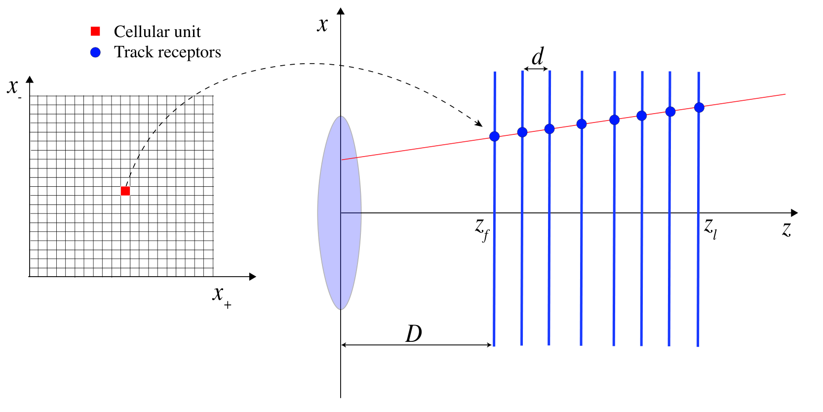
The space of track parameters () can be divided in a grid of cellular units. Each engine corresponds to a specific point () in the grid of track parameter space and is associated with the track parameters (). A set of corresponding receptors is identified with the intercepts of the track in the detector layers, as shown in Fig. 1. The expected time of the hit at layer is evaluated according to
| (2) |
where is the time of the track a . The distance of the track receptor to the measured -th hits
| (3) |
is fed to the engine which calculates the weight according to a Gaussian field response, , where is a parameter to be adjusted for optimal response. The receptors also provide an additional Gaussian response for the time of the hit, , where is the difference between the time of the -th measured hit and its expected value, and is the width of the field response. The engine weight function, , is defined as the sum over non negligible contributions
| (4) |
where is the contribution from the -th hit, defined as
| (5) | |||||
The weight is evaluated for three different hypotheses, where is the nominal bunch crossing time determined by the accelerator reference clock, and is proportional to the duration of the bunch crossing.


The evaluation of the weight function is performed in parallel for the appropriate engines and a track is identified by the local maximum at time . The reconstructed space and time parameters of the track are obtained by interpolations of the weight values adjacent to the maximum along the , and axes.
In particular the track parameters are determined by means of a Gaussian interpolation, defined as
| (6) | |||
| (7) |
where is the granularity of the grid of track parameters. Comparable results are obtained determining the parameters with a weighted average,
| (8) |
Similarly the time of the track can be evaluated by using a Gaussian interpolation along the time of the maximal weight value at grid position ,
| (9) |
where .
The contributions from hits not compatible with the time of the track are suppressed when including the time information in the retina algorithm. In Fig. 2, the weight distribution in the grid of track parameters is shown for an event with a real track in presence of background hits with no time information (left) and using time information of the hit (right). The plots correspond to a simulation with detector occupancy of 5% and resolution on the time of the hit of 10 ps. The suppression of out-of-time hits helps reducing local maxima in the weight distribution, shown in Fig. 2, that could generate fake tracks identification while improving the track parameter resolution, as discussed in Sec. 3.
3 4D tracking simulations
At the LHC the typical r.m.s. of the longitudinal size of the colliding proton bunches is 7.5 cm and the r.m.s. of the transverse size is few . In this scenario the proton-proton interactions are distributed in a region of about 10 cm, with an average of 1.4 interactions/mm. The primary interactions are distributed in time in an interval of about 330 ps around the nominal event time , determined by the accelerator reference clock while noise hits are uniformly distributed in time. The maximum value of the weight along is expected in the central bin at , and the weight values for are used for determining the time of the track by interpolation. In this study we set ps.
Simulations of the response of the 4D retina algorithm for a telescope made of 8 single-sided silicon strip detectors positioned along the axis have been performed. The strip pitch of the sensors is 180 m and the time resolution of the hits has been set to 10 ps. The distance between the detector layers is 4 cm and tracks are originated from an interaction region along the axis with Gaussian profile and positioned at a distance of 10 cm from the first plane, as represented in Fig. 1. Events with one track within the telescope acceptance have been generated and the artificial retina response has been simulated using a grid of about 20,000 cellular units uniformly distributed in the track parameter region with a granularity of 0.47 mm for both and .
Simulations of events with different level of detector occupancy (noise hits) have been performed with and without the time information of the hits to evaluate the effect on the track parameter resolutions. The obtained resolutions for the and track parameters are and , respectively, for events with no noise hits; the time of the track is determined with a precision of 3.5 ps. This is compatible with where is the number of measured hits.
When increasing the detector occupancy, background hits affect the quality of track reconstruction. The worsening of the resolution is in general due to the contamination of the weight function near the local maximum corresponding to an identified track. This effect can be reduced by increasing the granularity of the grid of cellular units and, as we demonstrate here, mitigating the effect of background out-of-time hits by using the time information in the fast tracking algorithm. In Fig. 3 are shown the residual distributions of generated minus reconstructed and track parameters for events with 5% detector occupancy. The resolutions obtained without using the time information are and . The performance decreases with respect to the case of events without noise hits. When including the time information of the hit the tracking performance improves and the resolution on track parameters become and . The results of the simulations of the 4D artificial retina algorithm are summarised in Table 1 and compared with resolutions obtained with offline track reconstruction by means of a simple fit. The residual distribution for the reconstructed minus the generated time of the track is shown in Fig. 4 for simulated events with noise hits. The obtained resolution is , to be compared with nominal value of ps for the case with no noise. The system provides a good determination of the time of the track even in presence of noise hits. The precise information on the time of the track can be used at later stages of event reconstruction to distinguish among particles coming from vertexes close in space but originated from proton-proton interactions occurring at different times.
| Configuration | time info | (m) | (m) | (ps) |
|---|---|---|---|---|
| no noise, offline | no | 23 | 15 | - |
| no noise, retina | no | 24 | 15 | - |
| no noise, retina | yes | 24 | 15 | 3.5 |
| with noise 5% occ., offline | no | 26 | 18 | - |
| with noise 5% occ., retina | no | 118 | 85 | - |
| with noise 5% occ., retina | yes | 42 | 28 | 6.3 |
4 Implementation of the 4D artificial retina algorithm in commercial FPGAs
The 4D artificial retina algorithm has been implemented on custom electronic boards developed in collaboration with Nuclear Instruments [11] based on Xilinx Kintex7 field-programmable gate array (FPGA). Using 512 cellular units for the grid of track parameters with a granularity of 3.3 mm the response of the algorithm was simulated at a clock frequency of 200 MHz. The choice of 512 engines is motivated by an existing implementation of the artificial retina algorithm with no time information [12] and found useful for comparing the utilization of resources in the two different cases.
The fast track finding architecture based on the artificial retina algorithm is composed by three different modules: the switch module that delivers the hits from the detector layers to appropriate processing units, a pool of engines for the calculation of the artificial retina response, and the track fitter module for the calculation of the track parameters by interpolation of the weight values. The latency of the response is estimated to be less than 100 time units: about 14 time units for the switch, 15 time units for the engine, 30 time units for the track fitter. This corresponds to a latency shorter than a microsecond at 200 MHz clock frequency, i.e. 1 time unit = 5 ns. The architecture of the system is shown in Fig. 5.
For the implementation of the 4D artificial retina algorithm, minor changes have been made to the switch and the track fitter logic modules with respect to the artificial retina algorithm implementation using spatial information only. The switch delivers in parallel the information of the hits from the data acquisition to the appropriate engines and the correct path for the hits is evaluated according to information stored in look-up tables (LUTs) . In particular the data routing path depends only on the space information of the hit and no change is required to the switch module.

For the case of the 4D artificial retina algorithm a modification to the architecture was necessary to the engine logic unit, shown in Fig. 6. The engine receives the hits with the information of the coordinate of the detector layer, the position of the measured cluster position and its time . The values and are evaluated according to two different LUTs whose values depend on the coordinate only. The exponentiation is performed in the FPGA using a LUT in order to save resources and reduce the latency of the response. The algorithm needs to evaluate a total of three weight values corresponding to the different track time hypotheses: , , . For each incoming -th hit the term is evaluated and then multiplied for three different time factors, . The same LUT is shared for the exponentiations. The four inputs are serialized and the outputs are deserialized allowing to instantiate only one LUT per engine. An hold signal is propagated from the engine back to the switch module for three clock cycles, until the engine is able to accept a new hit.
The multiplications between space and time Gaussian responses are implemented using DSP (digital signal processing) blocks. In the track fitter the and track parameters are evaluated, as for the case of the artificial retina algorithm, by interpolation of the weight values of the cells adjacent to the local maximum [12]. These modifications to the architecture of the system require a modest increase of FPGA resources of about 10%.
5 Conclusions and perspectives
Existing silicon pixel detectors achieved 150 ps time resolution and strong effort is ongoing to improve the time precision at the level of 10 ps. The use of precise space and time information for fast track finding systems would allow to use an additional dimension for discriminating signal and background events. A novel track finding algorithm using precise time and space information of the hit is proposed here. The 4D artificial retina algorithm allows the precise determination of the time of the track at the origin and a strong suppression of the contributions from background hits out of time. According to simulations the improvement in tracking performance is sizeable in presence of noise hits.
The algorithm is based on a massively parallel calculation and it is suitable for implementation in FPGAs with a pipelined architecture. The algorithm has been implemented in a Xilinx Kintex 7 FPGA with a modest increase of the resources, about 10%, with respect to the case where no time information was considered. These results are encouraging and represent a first step towards the development of a 4D fast track finding system for applications in future experiments at high luminosity.
Acknowledgements.
This work is supported by Istituto Nazionale di Fisica Nucleare, Italy. The authors would like to thank Andrea Abba for useful discussions.References
- [1] M. Fiorini, G. Aglieri Rinella, V. Carassiti, A. Ceccucci, E. Cortina Gil, A. Cotta Ramusino, G. Dellacasa and S. Garbolino et al., “High rate particle tracking and ultra-fast timing with a thin hybrid silicon pixel detector,” Nucl. Instrum. Meth. A 718, 270 (2013).
- [2] S. Parker, A. Kok, C. Kenney, P. Jarron, J. Hasi, M. Despeisse, C. Da Via and G. Anelli, “Increased speed: 3D silicon sensors. Fast current amplifiers,” IEEE Trans. Nucl. Sci. 58, 404 (2011).
- [3] H. Frisch et al., “Large Area Microchannel Plates for LAPPDTM,” PoS(TIPP2014)077 (2014).
- [4] N. Cartiglia, M. Baselga, G. Dellacasa, S. Ely, V. Fadeyev, Z. Galloway, S. Garbolino and F. Marchetto et al., “Performance of Ultra-Fast Silicon Detectors,” JINST 9, C02001 (2014), [arXiv:1312.1080].
- [5] W. Ashmanskas et al. [CDF collaboration], “Silicon vertex tracker: A Fast precise tracking trigger for CDF,” Nucl. Instrum. Meth. A 447, 218 (2000).
- [6] M. Shochet, L. Tompkins, V. Cavaliere, P. Giannetti , A. Annovi and G. Volpi et al. [ATLAS collaboration], “Fast TracKer (FTK) Technical Design Report Tech,” CERN-LHCC-2013-007 (2013).
- [7] J. Butler, D. Contardo, M. Kutle, J. Mans, L. Silvestris et al. [CMS collaboration], “Technical Proposal for the Phase-II Upgrade of the CMS Detector,” CERN-LHCC-2015-010 (2015).
- [8] L. Ristori, “An artificial retina for fast track finding,” Nucl. Instrum. Meth. A 453, 425 (2000).
- [9] A. Abba et al., “A specialized track processor for the LHCb upgrade,” CERN-LHCb-PUB-2014-026 (2014).
- [10] A. Abba, F. Bedeschi, M. Citterio, F. Caponio, A. Cusimano, A. Geraci, P. Marino and M. J. Morello et al., “A Specialized Processor for Track Reconstruction at the LHC Crossing Rate,” JINST 9, C09001 (2014), [arXiv:1406.7220].
- [11] Nuclear Instruments srl, IT-22045 Lambrugo (CO), Italy. http://www.nuclearinstruments.eu.
- [12] N. Neri et al., “First results of a detector embedded real-time tracking system with artificial retina,” Conference Record N1D3-1, IEEE NSS&MIC 2015.