Low Background Signal Readout Electronics for the Majorana Demonstrator
Abstract
The Majorana Collaboration will seek neutrinoless double beta decay (0) in 76Ge using isotopically enriched p-type point contact (PPC) high purity Germanium (HPGe) detectors. A tonne-scale array of HPGe detectors would require background levels below 1 count/ROI-tonne-year in the 4 keV region of interest (ROI) around the 2039 keV Q-value of the decay. In order to demonstrate the feasibility of such an experiment, the Majorana Demonstrator, a 40 kg HPGe detector array, is being constructed with a background goal of counts/ROI-tonne-year, which is expected to scale down to count/ROI-tonne-year for a tonne-scale experiment. The signal readout electronics, which must be placed in close proximity to the detectors, present a challenge toward reaching this background goal. This talk will discuss the materials and design used to construct signal readout electronics with low enough backgrounds for the Majorana Demonstrator.
Keywords:
neutrinoless double beta decay, germanium detector, low background electronicsClassification:
23.40-s, 23.40.Bw, 14.60.Pq, 27.50.+j1 Introduction to the Majorana Demonstrator
The Majorana Collaboration will build an array of isotopically enriched, high purity Germanium (HPGe) detectors in order to search for neutrinoless double-beta (0) decay[1] in 76Ge. Achieving a sensitivity to the 0half-life of years will require a tonne-scale array of detectors with a background rate below 1 count/ROI-t-y in the 4 keV region of interest around the 2039 keV Q-value for decay in 76Ge. The Majorana Demonstrator is currently being constructed in order to demonstrate the feasibility of constructing such an array[2]. The Demonstrator will contain 40 kg of p-type point contact (PPC) HPGe detectors[3], 30 kg of which will be composed of Germanium 87% isotopically enriched in 76Ge. Two separate modular arrays consisting of 7 strings of 4 or 5 detectors will be constructed in order to demonstrate scalability to a tonne-scale array. The Majorana Demonstrator has a background goal of 3 counts/ROI-t-yr, which is expected to scale down to 1 count/ROI-t-y due to effects such as self-shielding, based on simulations.

In order to achieve such a low background rate, multiple approaches are taken. The experiment will take place at the 4850 ft level of Sanford Underground Research Facility (SURF), in Lead, South Dakota, providing a 4260 mwe overburden to shield from cosmic rays. The detector modules will be housed in passive shielding against environmental background sources consisting of high density polyethylene, lead, and copper. Active background rejection approaches include a muon-veto system and rejection of multi-site events. Most -ray backgrounds will appear as multi-site events due to Compton scattering, and the low electric fields provided by PPC detectors produce multiple rises in these events that can be found by various analysis techniques. Furthermore, all components inside of the shielding will consist of radio-pure materials. In particular, the copper that forms the structure of the array will be ultra-pure electroformed copper (EFCu), produced and machined on the 4850 ft level of SURF. The amount of material placed inside of the shielding other than the HPGe detectors and EFCu is minimized.
In order to verify the purity of materials used for the Majorana Demonstrator, an extensive radio-assay and background-modeling campaign has been carried out. Four assay-techniques were used to determine the purity of materials:
- •
Direct -counting uses HPGe detectors to measure a background spectrum from components. This took place at underground facilities at the Waste Isolation Pilot Plant (WIPP) near Carlsbad, NM, the Kimballton Underground Research Facility (KURF) near Ripplemead, VA, and the low background facility (LBF) at Oroville, CA. The Oroville facility has recently moved to SURF.
- •
Inductively coupled plasma mass spectrometry (ICP-MS) was performed at facilities at Pacific Northwest National Laboratory (PNNL) and Lawrence Berkeley National Laboratory (LBNL). ICP-MS is the most sensitive technique to uranium and thorium backgrounds used by the Majorana Demonstrator.
- •
Glow discharge mass spectrometry (GDMS) was performed by the National Research Council of Canada (NRCC). GDMS offers high sensitivity to uranium and thorium content in conductive materials and was used primarily for the lead shielding.
- •
Neutron activation analysis (NAA) was performed, with test samples neutron activated at research reactors at the University of California, Davis’ McClellan Nuclear Radiation Center, North Carolina State University and Oak Ridge national Laboratory. Activation product levels were then measured at each of these sites or by the previously mentioned -counting facilities. NAA is used for low atomic mass materials such as plastics.
The detection efficiency of each detector to backgrounds from each component of the Majorana Demonstrator is estimated using a detailed simulation of the detector and shield geometry performed using Geant4[4]. The results of this simulation are combined with the assay results to obtain an estimate of the total background levels of the detector. In March, 2015, the expected background level was 3.1 counts/ROI-t-yr, with individual contributions from various components listed in Figure 2. The largest background contributions come from the signal readout electronics, consisting of the front-end boards, signal cables and signal connectors.

2 Signal Readout Electronics
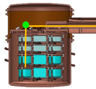
The signal readout electronics chain is responsible for collecting the charge from the Germanium detectors and carrying the signal to preamplifiers and digitizers outside of the shielding. The charge is collected by a contact pin at the point contact and shaped by front-end boards, which sit directly adjacent to the point contact of the detectors and act as the first stage of a charge sensitive amplifier for the signal. A bundle of four coaxial cables, called a detector bundle, carries the signal up along a string to the cryostat cold plate. A second bundle, the feedthrough bundle, carries the signal from the cold plate, along the thermosyphon crossarm, to a feedthrough flange outside of the shielding. The two cable bundles are connected by signal connectors directly above the cold plate. The path taken by the cables is depicted in Figure 4. Outside of the feedthrough flange, the signal is fed into preamplifiers and then digitized. Because the front-end boards, cable bundles, and signal connectors are all located inside of the shielding, it is critical that all three use a low-mass design with radiopure components in order to meet the Demonstrator’s background goals. The components must also be robust under vacuum cycling and thermal cycling to liquid nitrogen temperatures, and must be easy to use in a glove box without breaking.
2.1 Low-Mass Front-End Boards
The front-end boards use a design developed for the Majorana Demonstrator, called low-mass front-ends (LMFEs). The LMFEs are charge-sensitive amplifiers that use a resistive feedback design [5]. A charge-injection line is provided to allow characterization and monitoring of the LMFEs by external pulsers. The circuit is fabricated on a fused silica substrate. Gold traces are printed on the substrate on a titanium adhesion layer using photolithography. The feedback and charge-injection capacitances are provided by the geometric configuration of the traces. The feedback resistor consists of amorphous germanium, which can be made more radiopure than more common ceramic resistors using the same techniques used to produce HPGe detectors. A bare JFET die is attached to the substrate using low background silver epoxy, and connected to the circuit traces via wire bonding. The same Ag epoxy is used to attach the cable bundles to the LMFE. The LMFE board is mounted on an EFCu spring clip, which can be tensioned to provide a contact force between the gate pad of the LMFE circuit, a contact pin, and the point contact of a germanium detector. Figure 3 contains two photographs of an LMFE. ICP-MS assay of a full LMFE and spring clip has been performed, finding activities from uranium and thorium of 1.4 Bq/LMFE, resulting in an expected 0.60 counts/ROI-t-yr. Assays have also been performed on each individual material, shown in Table 1, resulting in an expected activity of 715 nBq/LMFE or 0.27 counts/ROI-t-yr. This discrepancy is most likely due to contamination from the handling of the materials during LMFE production. Increased care has been taken during subsequent LMFE production that may reduce backgrounds further.


| Material | Assay | Isotope | purity | MJD BG |
|---|---|---|---|---|
| Method | [pg/g] | [c/ROI/t/y] | ||
| Fused Silica | ICP-MS | 238U | 284 | 0.0616 |
| 232Th | 101 | 0.0259 | ||
| aGe | ICP-MS | 238U | 5000 | 0.0001 |
| 232Th | 5000 | 0.0001 | ||
| Au | ICP-MS | 238U | 2000 | 0.0015 |
| 232Th | 47000 | 0.0421 | ||
| Ti | ICP-MS | 238U | 100 | 0 |
| 232Th | 400 | 0 | ||
| FET die | ICP-MS | 238U | 141 | 0.0006 |
| 232Th | 2000 | 0.0107 | ||
| Al | ICP-MS | 238U | 91000 | 0.0004 |
| 232Th | 9.0 | 0 | ||
| Ag epoxy | -counting | 238U | 10000 | 0.0082 |
| 232Th | 70000 | 0.0685 | ||
| EFCu Spring Clip | ICP-MS | 238U | 0.015 | 0.0005 |
| 232Th | 0.014 | 0.0003 |
2.2 Signal Cables
The electrical signal is carried from the LMFE to a feedthrough flange through a 1.5 m bundle of four coaxial cables. The cables have an outer diameter of only 0.4 mm, and a linear mass density of 0.4 g/m. The signal cable is custom made by Axon’ Cable S.A.S. in France using commercially available clean copper. EFCu is not necessary due to the small size of the cables. The cables have an impedance of 50 for up to 2.2 m. Radio-assay of a short length of cable found activity of 0.059 Bq/m, contributing an estimated 0.085 counts/ROI-t-yr.


2.3 Signal Connectors
Signal connectors are necessary to connect the detector cable bundles to the feedthrough cable bundles above the cold plate of the cryostat. Commercially available electrical connectors cannot attain low enough backgrounds because they contain beryllium-copper (BeCu) electrical contact springs, which is difficult to purify of uranium and thorium to levels acceptable by the Majorana Demonstrator. Instead, a novel plug design with contact pins that contain no contact springs was used. The pins and sockets are misaligned so that the pin is forced to bend as it is inserted, and the spring action of the pin provides contact force. Mill-Max® gold-plated brass pins were used, with the contact springs removed. The pins are held in a Vespel® housing. The cables are attached using a low background tin-silver eutectic developed for the SNO experiment [6]. Strain relief is provided by fluorinated ethylene propylene (FEP) shrink tubing. Extensive quality control testing is necessary in order to ensure reliable connections. Full body assay of two signal connectors found activities of 1525 Bq/connector-pair, leading to a predicted 0.284 Counts/ROI-t-yr. Individual material assays, shown in Table 2 have found activities of 2110 Bq/connector-pair, with the largest component coming from the pins and sockets. Notice that the addition of contact springs would single-handedly triple Majorana Demonstrator’s background goal.
| Material | Assay | Mass [g per | Isotope | Activity | MJD BG |
|---|---|---|---|---|---|
| Method | conn. pair] | [Bq/kg] | [c/ROI/t/y] | ||
| Pins (w/BeCu) | ICP-MS | 0.112 | 238U | ||
| 232Th | |||||
| Pins (no BeCu) | ICP-MS | 0.112 | 238U | ||
| 232Th | |||||
| Vespel SP-1 | NAA | 0.95 | 238U | 1000 | 0.20 |
| 232Th | 12 | 0.01 | |||
| Solder | GDMS | 0.04 | 238U | ||
| 232Th | 12 | 0.0002 | |||
| Solder flux | GDMS | 0.04 | 238U | ||
| 232Th | 400 | 0.007 | |||
| FEP (shrink tube) | NAA | 0.001 | 238U | 1250 | 0.0001 |
| 232Th | 138 | 0.0001 | |||
| Total | 1.14 | 238U | 1520 | 0.28 | |
| 232Th | 593 | 0.34 |
3 Conclusion
In order to reach the Majorana Demonstrator’s background goal of 3 counts/ROI-t-yr, novel designs for signal readout electronics are necessary. Through miniaturization and the use of low-radioactivity materials, the low-mass front-end boards, signal bundles and BeCu-free signal connectors were created, helping to reduce the total background estimation to 3.1 counts/ROI-t-yr.
References
- (1) F.T. Avignone III, S.R. Elliott, and J. Engel, 2008 Double beta decay, Majorana neutrinos, and neutrino mass Rev. Mod. Phys., 80 481
- (2) N. Abgrall et al., 2014 The Majorana Demonstrator Neutrinoless Double Beta Decay Experiment Adv. High Energy Phys. 2014:365432
- (3) P.S. Barbeau, J.I. Collar, and O. Tench, 2007 Large-Mass Ultra-Low Noise Germanium Detectors: Performance and Applications in Neutrino and Astroparticle Physics Journal of Cosmology and Astroparticle Physics, 09 009
- (4) C. Cuesta et al., 2014 Background Model of the Majorana Demonstrator Preprint arXiv:1405.1370
- (5) P. Barton et al., 2011 Low-noise low-mass front end electronics for low-background physics experiments using germanium detectors, proceedings for Nuclear Science Symposium and Medical Imaging Conference (NSS/MIC), 2011 IEEE
- (6) J.F. Amsbaugh et al., 2007 An array of low-background 3He proportional counters for the Sudbury Neutrino Observatory, Nucl. Instrum. and Meth., A 579 1054-1080