Degrees of Freedom of Interference Channels with Hybrid Beam-formingThanks: The authors are with the DMC R&D Center, Samsung Electronics, Suwon, Republic of Korea.
Abstract
We study the sum degrees of freedom (DoF) of interference channels with hybrid beam-forming in which each transmitter uses antennas and RF chains and each receiver uses antennas and RF chains, where and , , and hybrid beam-forming composed of analog and digital precodings is employed at each node. For the two-user case, we completely characterize the sum DoF for an arbitrary number of antennas and RF chains by developing an achievable scheme optimized for the hybrid beam-forming structure and deriving its matching upper bound. For a general -user case, we focus on a symmetric case where , , , and , , and obtain lower and upper bounds on the sum DoF, which are tight when is an integer. The results show that hybrid beam-forming can increase the sum DoF of interference channel under certain conditions while it cannot improve the sum DoFs of point-to-point channel, multiple access channel, and broadcast channel. The key insights on this gain is that hybrid beam-forming enables users to manage inter-user interference better, and thus each user can increase the dimension of interference-free signal space for its own desired signals.
Index Terms:
Degrees of freedom, hybrid beam-forming, interference alignment, interference channelI Introduction
Mobile data traffic has been growing dramatically as the number of mobile smart devices is increasing rapidly in recent years [1]. To accommodate tremendous demand on mobile data traffic, the cell capacity can be largely increased by deploying a very large number of antennas at base stations (BSs), often referred to as a massive multiple-input multiple-output (MIMO) system [2, 3]. The massive MIMO system, however, has hardware constrains that come from using a few hundred antennas. For a conventional antenna array structure, each antenna needs to have a dedicated RF chain. This naturally leads to an increment in the circuit size, power consumption, and device cost proportionally to the number of antennas, and hence it can be a serious problem in a practical point of view especially for massive MIMO systems. Therefore, to resolve this problem, a hybrid beam-forming structure with a lower number of RF chains than the number of antenna elements has been recently introduced as a practical solution [4, 5].
As an alternative approach to increase the cell capacity, millimeter-wave (mmWave) communications have attracted great attention recently [6]. The mmWave band from 30 to 300 GHz provides abundant contiguous frequency resources while frequency bands under 5 GHz used for legacy cellular communications are very crowded and fragmented. The main advantage in mmWave communications is that a very high data rate can be supported using a very large bandwidth at mmWave bands. However, one of major drawbacks is the high induced path loss due to the propagation loss and absorption loss at mmWave bands [7]. Fortunately, this high path loss can be effectively compensated by a high beam-forming gain obtained from a large number of antenna elements that can be packed into a small form factor due to the small wavelength in mmWave bands. To support a single stream only, the analog beam-forming, which is simply implemented by controlling attenuators and phase shifters of the antenna array to steer a directional beam, is enough to be considered. However, to transmit multiple streams, the hybrid beam-forming structure, where analog beam-forming is performed at RF domain and antenna arrays are connected to a relatively small number of digital paths, should be considered to get the multiplexing gain [8, 9].
As mentioned above, the hybrid beam-forming architecture can play a key role in the next generation communications (e.g., massive MIMO and/or mmWave communications) and hence has been widely studied recently [8, 9, 10, 11, 12]. In [8], precoders and combiners are designed using a sparse reconstruction approach. In [10], baseband and RF beams are designed for multiuser downlink spatial division multiple access (SDMA). In addition, a hybrid precoding algorithm based on a hierarchical codebook is proposed in [11]. Furthermore, a hybrid precoder is proposed for massive multiuser MIMO systems in [12]. While there are some works on hybrid beam-forming structures, however, to the best of our knowledge, the degrees of freedom (DoF) gain from hybrid beam-forming has not been analyzed before.
I-A Previous Works
The DoF, which is also known as a capacity pre-log, gives the capacity approximation at high signal to noise ratio (SNR) regime. For example, for the point-to-point (PTP) channel with transmit antennas and receive antennas, it is well known that the capacity increases with the growth rate at high SNR [13, 14]. Since exact capacity characterization is generally still unknown even for simple networks (e.g., two-user interference channel), instead of obtaining an exact capacity, approximate characterization by finding the optimal DoF has been studied in many networks recently [15, 16, 17, 18, 19, 20, 21, 22, 23, 24, 25, 26, 27, 28, 29, 30, 31].
Specifically, for the two-user interference channel, the sum DoF has been completely characterized, where zero-forcing precoding has been shown to be enough to achieve the optimal DoF [15]. For a general -user interference channel, a novel interference management technique called interference alignment has been proposed in [16, 19], which achieves the optimal sum DoF of . Later this scheme has been extended to MIMO configurations both for rich scattering environment [23, 22] and poor scattering environment [29, 30, 31]. Furthermore, beyond the interference channels, the idea of interference alignment has been successfully adapted to various networks, e.g., see [17, 18, 19, 20, 21, 24, 25, 26, 27, 28] and references therein.
I-B Contributions
In this paper, our primary goal is to answer if hybrid beam-forming can increase the sum DoF of interference channels. To this end, motivated by the aforementioned previous works, we propose zero forcing and interference alignment schemes optimized for the hybrid beam-forming structure. In addition, we also derive a new upper bound on the sum DoF when hybrid beam-forming is employed at each node. For the two-user case, this upper bound coincides with the achievable sum DoF of the proposed scheme, thereby completely characterizing the sum DoF. For a general -user case, our proposed scheme can achieve the upper bound when is an integer, where and denote the number of antennas at each transmitter and receiver, respectively. As a consequence of the result, we show that hybrid beam-forming can indeed improve the sum DoF of the -user interference channel under certain conditions. This is in contrast to the PTP channels, multiple access channel (MAC), and broadcast channel (BC) cases in which hybrid beam-forming cannot increase the sum DoF (see Section III). The key insight behind this gain is that hybrid beam-forming enables users to manage interference better, and thus each user can increase the dimension of interference-free signal space which can be used for its own desired signals.
I-C Organization
The rest of this paper is organized as follows. In Section II, we describe the system model and sum DoF metric considered in this paper. In Section III, we give an intuition as to how hybrid beam-forming can increase the sum DoF through motivating examples. In Section IV, we present and discuss about the main results of this paper. In addition, we provide numerical results which show the performance improvement from hybrid beam-forming in Section V. In Sections VI and VII, we provide the proofs of the main theorems. Finally, we conclude the paper in Section VIII.
I-D Notations
Throughout the paper, we will use , , and to denote a matrix, a vector, and a scalar, respectively. For a rational number , the notation denotes the integer part of . For matrix , let , , and denote the transpose, the complex conjugate transpose, and the norm of , respectively. In addition, let and denote the determinant and the rank of , respectively. The notations and denote the identity matrix and zero matrix, respectively. We write if .
II System Model
Consider a -user interference channel with hybrid beam-forming, as shown in Fig. 1. Transmitter wishes to communicate with receiver only, while causing interference to all the other receivers. In addition, transmitter uses antennas and RF chains and receiver uses antennas and RF chains, where and , . Specially, when and , , we call the corresponding channel as a full digital channel.

II-A Channel Model
Similar to previous works [8, 10], in this paper we assume that transmitter utilizes transmit hybrid beam-forming which consists of an analog precoder and an digital precoder as depicted in Fig. 1, where denotes the number of streams of user .11 1 As compared to the hybrid beam-forming structure introduced in [8, 10], in this paper, coefficients in can have different norms by relaxing the constraint that all entries are of equal norm. In practical point of view, this is feasible since we can implement by using both attenuators and analog phase shifters rather than using analog phase shifters only. In addition, based on this hybrid beam-forming, the input signal of transmitter at time slot , , is assumed to be given by
where is the baseband-domain input vector and
is the symbol vector of transmitter . Here, denotes the th symbol of user at time slot . Then the input and output relationship at RF domain is given by
where is the channel matrix from transmitter to receiver , is the RF-domain received signal vector at receiver , and is the Gaussian noise vector at receiver whose entries are drawn from . We assume that all channel coefficients are independent and identically distributed (i.i.d) from a continuous distribution and known to all nodes.
After receiving , receiver applies receive hybrid beam-forming which consists of an analog precoder and a digital precoder as shown in Fig. 1. Specifically, by applying the analog precoder to the received signal at RF domain, we can obtain the input and output relationship at baseband domain as
where , , and . If we further apply the digital precoder to the received signal at baseband domain, we finally get
where , , and . Note that is the effective channel matrix which can be obtained after applying transmit hybrid beam-forming of transmitter and receive hybrid beam-forming of receiver .
Finally, by applying the aforementioned hybrid beam-forming strategy and assuming Gaussian signaling , the following average sum rate is achievable for a given transmit power [32]:
| (1) |
where . Specifically, when all the interferences are eliminated via hybrid beam-forming, i.e., , and , (1) becomes
| (2) | ||||
| (3) |
II-B Encoding, Decoding, and Sum DoF
There are independent messages . For each transmitter , a message is mapped to an length codeword . To send the message , at time , transmitter sends . Here, we assume that each transmitter should satisfy the average power constraint , i.e., for . Then receiver decodes its desired message , based on its received signal.
A rate tuple is said to be achievable for the channel if there exists a sequence of codes such that the average probability of decoding error tends to zero as the code length goes to infinity. The capacity region of this channel is the closure of the set of achievable rate tuples . The sum DoF , which is also known as a sum-capacity pre-log, provides the sum capacity approximation at high SNR as22 2 In this paper, when we derive lower and upper bounds on the sum DoF, we restrict our attention on the cases in which the hybrid beam-forming structure introduced in Section II-A is used.
Equivalently, the sum DoF can be defined as .
III Preliminary Discussion
To gain insights into the DoF gain from hybrid beam-forming, we begin with examining PTP channel, MAC, and BC cases. Note that the PTP channel, the -user MAC, and the -user BC can be obtained from the -user interference channel by allowing full cooperation among all the transmitters and among all the receivers, full cooperation among all the receivers only, and full cooperation among all the transmitters only, respectively. Here, we assume that hybrid beam-forming strategy (including digital precoder and analog precoder) for each channel is employed in a similar manner as in Section II.
III-A Point-to-Point (PTP) Channel
Consider the PTP channel in which the transmitter uses RF chains and antennas and the receiver uses RF chains and antennas. The DoF of this channel is stated in the following lemma.
Lemma 1
For the PTP channel with hybrid beam-forming, the DoF is given by .
Proof:
We first provide a converse proof. Following a similar way described in Section II, we can write the input and output relationship of the PTP channel at time slot as
where is the RF-domain output vector at the receiver, is the channel matrix from the transmitter to the receiver, and are the RF-domain input vector and the baseband-domain input vector at the transmitter, respectively, is the analog precoder of the transmitter, and is the Gaussian noise vector.
Now focus on the input and output relationship at baseband domain. By applying receive analog precoding at the receiver, we can get
where is the analog precoder of the receiver, , and . Since , we see that .
For achievability, we only use transmit antennas out of antennas of the transmitter and receive antennas out of antennas of the receiver to equivalently create a conventional full digital PTP channel with transmit antennas and receive antennas. Therefore, is achievable [13, 14], which completes the proof. ∎
It is well known that the DoF of the full digital PTP channel with transmit antennas and receive antennas is equal to [13, 14]. Therefore, from the result of Lemma 1, we see that adding more antennas only cannot increase the DoF of a PTP channel without increasing the number of RF chains, regardless of the values of and .
III-B Multiple Access Channel (MAC) and Broadcast Channel (BC)
Now we consider the -user MAC and BC with hybrid beam-forming. For the MAC case, each transmitter uses RF chains and antennas and the receiver uses RF chains and antennas. For the BC case, the transmitter uses RF chains and antennas and each receiver uses RF chains and antennas. The DoFs of these channels are stated in the following lemmas.
Lemma 2
For the -user multiple access channel (MAC) with hybrid beam-forming, the DoF is given by .
Proof:
For a converse proof, we allow full cooperation among all the transmitters to form PTP channel. Then, from the result of Lemma 1, the sum DoF of this network is equal to . Since allowing cooperation does not reduce the capacity region [17], this is an upper bound of the original network, and thus
For achievability, we use only antennas out of antennas of transmitter , , and antennas out of antennas of the receiver to form a conventional full digital MAC in a similar manner as in Lemma 1. Then, is achievable [15], which completes the proof. ∎
Lemma 3
For the -user broadcast channel (BC) with hybrid beam-forming, the DoF is given by .
Proof:
We can easily prove Lemma 3 by following similar proof steps in Lemma 2 except the fact that we now allow full cooperation among all the receivers instead of transmitters for a converse proof. For brevity, we omit the rest of the proof steps. ∎
From the results of Lemmas 2 and 3, adding more antennas only without more RF chains cannot increase the sum DoFs of MAC and BC, as in the PTP case. Therefore, we can see that when full cooperation is already allowed at either transmitter side or receiver side of the -user interference channel, hybrid beam-forming cannot further improve the DoF. However, as we will show in the following example, for the case in which full cooperation is not allowed so that there exist inter-user interferences, the sum DoF of an interference channel can be improved via hybrid beam-forming for certain cases.
III-C Interference Channel: Motivating Example
Now we provide a simple example where hybrid beam-forming indeed improves the sum DoF. In the following example, we omit the time index for brevity.
Example 1
Consider the two-user interference channel where and , . We first set the analog precoder to satisfy for and . Since is the matrix and all channel coefficients are generic, we can easily find that satisfies these conditions. In addition, for the digital precoder of transmitter , we set , . Then, the received signal at each receiver is given by
where is the transmitted symbol vector of user and . Since , we can achieve for each user, thus achieving . Note that for the two-user full digital interference channel, which has the same number of RF chains as in the two-user interference channel, only the sum DoF of two can be achieved. This shows that for some cases, the sum DoF of an interference channel can actually be increased by adding more antennas only without increasing the number of RF chains.
Remark 1
As shown in Example 1, by using more antennas, we can have a better ability to null out interferences from/to other users at RF domain. This enables users to secure more interference-free dimensions, and as a result, a higher sum DoF is achievable without any additional RF chains for some cases. However, despite this improved capability dealing with interferences, hybrid beam-forming does not always increase the DoF of an interference channel. For instance, as will be demonstrated in the next example, if all the interferences can be eliminated without the need to add more antennas, hybrid beam-forming cannot increase the sum DoF.
Example 2
Consider the two-user interference channel where , , , and , . By allowing full cooperation among transmitters and among receivers, we can get the PTP channel. Since the DoF of this channel is given by two from Lemma 1 and allowing full cooperation does not reduce the capacity region, the sum DoF of the two-user interference channel cannot be more than two. Note that the two-user full digital interference channel can also achieve the sum DoF of two [15]. Therefore, unlike in Example 1, adding antennas only cannot increase the sum DoF in this case. In fact, in this case, to achieve a higher DoF, we need to use more RF chains as well as more antennas. For example, if we use additional one RF chain and two RF chains at each transmitter and receiver, respectively, the channel becomes the two-user full digital interference channel, and we can now achieve the improved DoF of 4.
IV Main Results
In this section, we state and discuss about the main results of this paper. For the two-user case, the sum DoF is completely characterized for any antenna configuration. When , we focus on a symmetric case where , , , and , , and derive lower and upper bounds on the sum DoF. It is shown that two bounds are matched under a certain condition.
IV-A Two-user Case
For the two-user interference channel, we completely characterize the sum DoF as stated in the following theorem.
Theorem 1 (Two-user case)
For the two-user interference channel with hybrid beam-forming, the sum DoF is given by
where and for .
Proof:
See Section VI for the proof. ∎
Remark 2
For the case where and , , the sum DoF becomes
which recovers the result for the two-user full digital interference channel in [15].

Remark 3
Note that when the condition
is satisfied, the sum DoF becomes
which is the sum DoF of the interference-free channel. Therefore, we can see that by adding enough number of antennas at each node, all the users can utilize their full DoFs as if there is no interference.
DoF gain due to hybrid beam-forming: Consider a symmetric case where and . We plot the sum DoF as a function of with fixed in Fig. 2. For comparison, we also plot the sum DoF of the full digital case where the number of RF chains is the same as the hybrid beam-forming case. As can be seen in Fig. 2, although we add antennas only, we can achieve a higher DoF and it reaches up to the maximum value of , the sum DoF of the interference-free channel, when . The gain comes from the fact that hybrid beam-forming can null out more interferences without increasing the number of RF chains, as well as enhancing the capacity of PTP channel as reported in [8, 10].
IV-B -user Case
When , we focus on a symmetric case where , , , and , . Under this configuration, we obtain lower and upper bounds on the sum DoF as stated in the following theorem, which are tight when is an integer.
Theorem 2 (-user case)
For the symmetric -user interference channel with hybrid beam-forming, the following sum DoF is achievable:
where . For converse, the sum DoF is upper bounded by
Proof:
See Section VII for the proof. ∎
Remark 4
Similar to the two-user case explained in Remark 2, for the case where and , Theorem 2 recovers the result for the -user full digital interference channel in [23].
Remark 5
It is easy to see that is a non-decreasing function of and . Intuitively, this is clear since having more antennas does not reduce the capacity region. Moreover, when each user can achieve the maximum DoF of as if there is no interference.
Corollary 1
By employing hybrid beam-forming, we can get at most two-fold DoF gain as compared to the full digital case in which the number of RF chains is the same as the hybrid beam-forming case.
Proof:
Let and denote the sum DoFs with hybrid beam-forming and full digital structures, respectively. For the two-user case, we have
In addition, for the general -user case, we have
where . This completes the proof. ∎

DoF gain due to hybrid beam-forming: Consider the three-user case where . First, we set and plot the sum DoF as a function of with fixed and in Fig. 3. In addition, we consider another scenario in which additional antennas are employed only at transmitters, i.e., , and again plot the sum DoF as a function of . As can be seen in the figure, by using hybrid beam-forming, we can achieve a higher DoF and interestingly, it can reach up to the maximum DoF of six even when hybrid beam-forming is applied at transmitters only. Furthermore, note that when achieving this DoF, interference alignment combined with hybrid beam-forming is employed. From this point, we can see that hybrid beam-forming can provide an improved capability not only nulling out interferences but also aligning interferences at RF domain.

Now, we examine a tendency of the sum DoF with respect to with the fixed number of antennas and RF chains at each node. Specifically, we set and plot the sum DoFs when and in Fig. 4. For comparison, we also plot the sum DoF of the full digital case where the number of RF chains is the same as the hybrid beam-forming case. From Fig. 4, we see that hybrid beam-forming can improve the sum DoF for all values of , and moreover, the slope also increases as the number of additional antennas at each receiver increases.
V Numerical Simulation
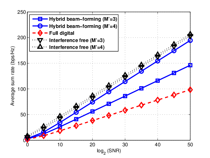
In this section, we numerically evaluate the average sum rate performance of the proposed hybrid beam-forming schemes for and cases to show that the sum DoFs stated in Theorems 1 and 2 are indeed achievable. For comparison, the sum DoFs of the full digital and the interference-free cases are also plotted. Here, we assume Rayleigh fading environment where each channel coefficient is drawn i.i.d from . In addition, we assume that all the noise power is normalized to unity and thus . Furthermore, to clearly capture the sum DoFs from the sum-rate graphs, we plot the average sum rates as a function of .
V-A Average Sum Rate for the Two-user Case
In Fig. 5, the average sum rates are plotted as a function of , where and . Note that the sum DoFs can be observed from the slopes in the figure. We can see that the sum DoFs obtained by the simulation are well matched with the sum DoFs stated in Lemma 1 and Theorem 1. Here, when the simulation is performed, the number of streams of hybrid beam-forming for each user is set by and for and for by following Theorem 1.
As shown in the figure, the full digital scheme can only achieve the sum DoF of two, while the sum DoF of the interference-free channel is four. When hybrid beam-forming is employed, we can see by simulation that the sum DoF can be improved and even reach up to the interference-free DoF, as shown in Theorem 1, and therefore the performance gap between hybrid beam-forming and full digital cases dramatically increases as the SNR increases.

V-B Average Sum Rate for the Three-user Case
As in the previous subsection, the average sum rate is plotted as a function of in Fig. 6, where . When hybrid beam-forming is used, we consider the two different scenarios in which additional antennas are employed only at transmitters, i.e., for and 6, and additional antennas are employed both at transmitters and receivers, i.e., for and 6. Here, we adopt the distributed interference alignment33 3 Note that the achievable scheme proposed in Theorem 2 requires an arbitrary large number of symbol extension. Therefore, in this subsection, instead of adopting the achievable scheme in Theorem 2 directly, we employ the DIA algorithm to numerically show that the sum DoF stated in Theorem 2 is indeed feasible. Here, Theorem 2 provides theoretical guidance when selecting a suitable number of streams for each user. (DIA) algorithm proposed in [33] for numerical simulation and the number of streams of hybrid beam-forming used for the simulation is given by Theorem 2. The slopes in the figure show that the sum DoFs stated in Theorem 2 is indeed achievable.
The full digital scheme can only achieve the sum DoF of three, while the sum DoF of the interference-free channel is six as shown in the figure. As in the two-user case, the sum DoF of the full digital scheme is only half of that of the interference-free channel. When and , the hybrid beam-forming can achieve the maximum sum DoF of six as if there is no interference between users. Interestingly, for the case in which additional antennas are employed only at transmitters , the sum DoF can also be increased as compared to the full digital case, and the performance gain over the full digital case increases as the number of additional antennas increases.
VI Proof of Theorem 1
VI-A Achievability
In our achievable scheme, we will use only transmit RF chains out of RF chains of transmitter and receive RF chains out of RF chains of receiver , for all . Hence, from now on, we can equivalently consider the interference channel instead of the original channel, the interference channel. In addition, since our achievable scheme operates in a single time slot, we omit the time index for brevity.
We design the input signal of transmitter as
where is the transmit analog precoder, is the transmit digital precoder, and is the vector of transmitted Gaussian symbols of user . To be specific, beam-forming vectors in can be decomposed into two parts:
- •
denotes the th beam-forming vector in such that and , where . Note that since the size of is given by and channel matrices are drawn i.i.d from a continuous distribution, the maximum number of linearly independent beam-forming vectors satisfying this condition is . Let denote the number of such vectors.
- •
denotes the th beam-forming vector in whose coefficients are randomly generated from a continuous distribution and , where has a finite value. Hence, and for with probability one. Let denote the number of such vectors. In addition, we further restrict and to satisfy .
In summary, we choose , , , , , and to satisfy the following conditions.
| (4) | ||||
| (5) | ||||
| (6) | ||||
| (7) | ||||
| (8) | ||||
| (9) |
Then the received signal at receiver at RF domain is given by
where (10) is due to the properties of and .
Now we explain the beam-forming matrix at receiver . Denote as the receive analog precoder and as the receive digital precoder. We set such that and . Since we have
we can find satisfying these conditions. Therefore, after applying receive analog precoding, we obtain
Recall that . Now, we set and as the left and right singular matrices of the matrix , respectively. Then we get parallel AWGN channels for user after applying the receive digital precoding as follows:
where is the diagonal matrix with the singular values of on the diagonal and . Therefore, we can see that each user achieves DoF via the proposed scheme, and thus the achievable total DoF is given by .
Finally, by evaluating the conditions (4)–(9) using the Fourier-Motzkin elimination, we get the desired bound:
which completes the achievability proof of Theorem 1.
VI-B Converse
From the result of Lemma 1, the DoF of the PTP channel for each user is equal to . Therefore, for the two-user interference channel, the sum DoF cannot be more than , i.e.,
| (11) |
Now suppose we add transmit RF chains at transmitter and receive RF chains at receiver for all to form the conventional full digital interference channel. Then the sum DoF of this channel is upper bounded by
| (12) |
from the result of [15]. Clearly, adding more RF chains does not reduce the capacity region, and hence (12) is also an upper bound for the original channel.
Combining (11) and (12), we get the desired upper bound as
which completes the converse proof of Theorem 1.
VII Proof of Theorem 2
VII-A Achievability
Our achievability is motivated by the interference alignment scheme proposed for the -user full digital interference channel in [23]. Here, we extend the previous scheme to be suitable for the general -user interference channel with hybrid beam-forming. For brevity, we focus on explaining the steps needed for hybrid beam-forming cases.
Consider the ratio . Similar in [23], when , our achievable scheme is based on zero forcing while it is based on interference alignment when . Note that reciprocity holds for both zero forcing and interference alignment, i.e., the achievable sum DoF of the -user interference channel via zero forcing and/or interference alignment is equal to the that of the -user interference channel [16, 33]. Therefore, without loss of generality, we assume that , which results in .
VII-A1
In this case, since our achievable scheme operates in a single time slot, we omit the time index for brevity.
Each transmitter sends data streams using hybrid beam-forming, i.e.,
where is the transmit analog precoder, is the transmit digital precoder, and is the vector of transmitted Gaussian symbols of user . Here we set that coefficients of and are randomly generated from a continuous distribution and , where has a finite value. Then the received signal at receiver at RF domain is given by
Observe that and , . Since , we can completely null out all the interference at each receiver by setting analog beam-forming matrix, , as
while can also be satisfied for the desired signals. As a result, each user can achieve DoF, and thus achieving .
VII-A2
In this case, before we explain our achievable scheme, we first refer to the following Lemma in [23].
Lemma 4
For the -user full digital single–input multiple–output (SIMO) interference channel, the sum DoF of can be achieved.
Proof:
The proof is provided in [23, Theorem 2]. ∎
Now consider the –user full digital SIMO interference channel. By adapting the achievable scheme in Lemma 4, we can achieve the sum DoF of . To be specific, under this scheme, symbol extension of the original channel is considered, where and is an arbitrary integer, and each user achieves DoF and each user achieves DoF over the extended channel, i.e.,
In addition, by applying the scheme, it turns out that the dimensions of the signal space spanned by the desired signal vectors and interference signal vectors at receiver are given by and out of the dimensional signal space, respectively, while they are given by and , respectively, at receiver . Let denote the beam-forming matrix of transmitter used for the extended channel of the -user interference channel. We denote the elements of as
where means the th beam-forming coefficient of transmitter at time slot .
Then, now consider the original channel, the -user interference channel. Here, we only use antennas out of antennas at each receiver by discarding antennas at each receiver, which results in the -user interference channel, and then apply the -time symbol extension as in the -user interference channel, which gives the overall channel matrix between transmitter and receiver as
For this extended channel, by employing beam-forming coefficients proposed in the -user interference channel, we design the analog beam-forming matrix of transmitter as
where
and Note that the number of column vectors in is given by for , for , and for , i.e.,
where . In addition, we set the digital precoder of transmitter over the extended channel as
where . Observe that we can choose first column vectors of out of vectors by multiplying and as . Therefore, from the results of Lemma 4, we can see that the dimension of the signal space spanned by the desired signal vectors at receiver is equal to and the dimension of the signal space spanned by the interference signal vectors at receiver is less than or equal to out of the dimensional space. Hence, we can null out all the interferences at receiver via zero forcing beam-forming over the extended channel, by setting as the matrix such that and . Furthermore, by setting the receive digital beam-forming matrix of receiver over the extended channel, , as , each user can achieve DoF over the extended channel.
Finally, the achievable sum DoF is given by
which completes the proof of the achievability of Theorem 2.
VII-B Converse
VII-B1
Recall that from Lemma 1, the DoF of the PTP channel is equal to . Therefore, for the -user interference channel, the sum DoF cannot be more than , i.e., .
VII-B2
Let denote the DoF for each user . Similar in [23, 17], we first focus on an upper bound on . We eliminate all the messages except , which does not decrease and results in the -user interference channel. Now we allow full cooperation among transmitters and among receivers to form the two-user interference channel, where , , , , , , , and . Then, from the result of Theorem 1, the sum DoF of this channel is given by
| (13) |
Since allowing full cooperation among some transmitters and among some receivers does not reduce the capacity region, (13) is also an upper bound for the original channel. Due to the symmetry, by picking any users out of users, we have the following upper bound for the original channel:
| (14) |
for all with . Hence, summing up all such bounds, we finally have
VIII Conclusion
In this paper, we studied the sum DoF of the -user MIMO interference channels where each user is equipped with a larger number of antennas than the number of RF chains. For the two-user case, the sum DoF was completely characterized for arbitrary numbers of antennas and RF chains. For the -user case (), the achievable DoF was derived under the symmetric antenna configuration. It is shown that our achievable scheme is optimal in achieving the sum DoF of the user hybrid beam-forming systems if the ratio is equal to an integer, where and denote the number of antennas at each transmitter and receiver, respectively.
Our work has revealed that hybrid beam-forming can provide a significant gain by nulling out interferences between users, and the gain dramatically increases as SNR increases. Moreover, interestingly, even the sum DoF performance of the interference-free channel can be achieved if we add enough number of antennas at either transmitter or receiver side only. Therefore, the results of this paper imply that employing hybrid beam-forming can be an attractive solution for enhancing the capacity of interference-limited networks.
References
- [1] CISCO, “Cisco visual networking index: Global mobile data traffic forecast update, 2012–2017,” White paper, Feb. 2013.
- [2] T. L. Marzetta, “Noncooperative cellular wireless with unlimited numbers of base station antennas,” IEEE Trans. Wireless Commun., vol. 9, no. 11, pp. 3590–3600, Nov. 2010.
- [3] L. Lu, G. Y. Li, A. L. Swindlehurst, A. Ashikhmin, and R. Zhang, “An overview of massive MIMO: Benefits and challenges,” IEEE J. Sel. Top. Signal Process., vol. 8, no. 5, pp. 742–758, Oct. 2014.
- [4] X. Zhang, A. F. Molisch, and S.-Y. Kung, “Variable-phase-shift-based RF-baseband codesign for MIMO antenna selection,” IEEE Trans. Signal Process., vol. 53, no. 11, pp. 4091–4103, Nov. 2005.
- [5] V. Venkateswaran and A.-J. van der Veen, “Analog beamforming in MIMO communications with phase shift networks and online channel estimation,” IEEE Trans. Signal Process., vol. 58, no. 8, pp. 4131–4143, Aug. 2010.
- [6] T. S. Rappaport, S. Shun, R. Mayzus, H. Zhao, Y. Azar, K. Wang, G. N. Wong, J. K. Schulz, M. Samimi, and F. Gutierrez, “Millimeter wave mobile communications for 5G cellular: It will work!” IEEE Access, vol. 1, pp. 335–349, May 2013.
- [7] M. Marcus and B. Pattan, “Millimeter wave propagation: Spectrum management implications,” IEEE Microwave Mag., vol. 6, no. 2, pp. 54–62, Jun. 2005.
- [8] O. E. Ayach, S. Rajagopal, S. Abu-Surra, Z. Pi, and R. W. Heath Jr., “Spatially sparse precoding in millimeter wave MIMO systems,” IEEE Trans. Wireless Commun., vol. 13, no. 3, pp. 1499–1513, Mar. 2014.
- [9] A. Alkhateeb, J. Mo, N. González-Prelcic, and R. W. Heath Jr., “MIMO precoding and combining solutions for millimeter-wave systems,” IEEE Commun. Mag., vol. 52, no. 12, pp. 122–131, Dec. 2014.
- [10] S.-H. Wu, L.-K. CHiu, K.-Y. Lin, and T.-H. Chang, “Robust hybrid beamforming with phased antenna arrays for downlink SDMA in indoor 60 GHz channels,” IEEE Trans. Wireless Commun., vol. 12, no. 9, pp. 4542–4557, Sep. 2013.
- [11] A. Alkhateeb, O. E. Ayach, G. Leus, and R. W. Heath, “Channel estimation and hybrid precoding for millimeter wave cellular systems,” IEEE J. Sel. Topics Signal Process., vol. 8, no. 5, pp. 831–846, Oct. 2014.
- [12] L. Liang, W. Xu, and X. Dong, “Low-complexity hybrid precoding in massive multiuser MIMO systems,” IEEE Wireless Commun. Lett., vol. 3, no. 6, pp. 653–656, Dec. 2014.
- [13] G. J. Foschini and M. J. Gans, “On limits of wireless communications in a fading environment when using multiple antennas,” Wireless Pres. Commun., no. 6, pp. 311–335, Mar. 1998.
- [14] E. Telatar, “Capacity of multiple-antenna Gaussian channels,” Europ. Trans. Telecomm. (ETT), vol. 10, no. 6, pp. 585–596, Nov. 1999.
- [15] S. A. Jafar and M. J. Fakhereddin, “Degrees of freedom for the MIMO interference channel,” IEEE Trans. Inf. Theory, vol. 53, no. 7, pp. 2637–2642, Jul. 2007.
- [16] V. R. Cadambe and S. A. Jafar, “Interference alignment and degrees of freedom for the -user interference channel,” IEEE Trans. Inf. Theory, vol. 54, no. 8, pp. 3425–3441, Aug. 2008.
- [17] ——, “Degrees of freedom of wireless networks with relays, feedback, cooperation, and full duplex operation,” IEEE Trans. Inf. Theory, vol. 55, no. 5, pp. 2334–2344, May 2009.
- [18] ——, “Interference alignment and the degrees of freedom of wireless networks,” IEEE Trans. Inf. Theory, vol. 55, no. 9, pp. 3893–3908, Sep. 2009.
- [19] A. Motahari, S. O. Gharan, and A. Khandani, “Real interference alignment: Exploiting the potential of single antenna systems,” IEEE Trans. Inf. Theory, vol. 60, no. 8, pp. 4799–4810, Aug. 2014.
- [20] C. Suh and D. Tse, “Interference alignment for cellular networks,” in Proc. 46th Annu. Allerton Conf. Communication, Control, and Computing, Monticello, IL, Sep. 2008, pp. 1037–1044.
- [21] ——, “Downlink interference alignment,” IEEE Trans. Commun., vol. 59, no. 9, pp. 2616–2626, Sep. 2011.
- [22] A. Ghasemi, A. S. Motahari, and A. K. Khandani, “Interference alignment for the user MIMO interference channel,” in Proc. IEEE Int. Symp. Information Theory, Austin, TX, Jun. 2010, pp. 360–364.
- [23] T. Gou and S. A. Jafar, “Degrees of freedom of the user MIMO interference channel,” IEEE Trans. Inf. Theory, vol. 56, no. 12, pp. 6040–6057, Dec. 2010.
- [24] S.-W. Jeon, S.-Y. Chung, and S. A. Jafar, “Degrees of freedom region of a class of multisource Gaussian relay networks,” IEEE Trans. Inf. Theory, vol. 57, no. 5, pp. 3032–3044, May 2011.
- [25] T. Gou, S. A. Jafar, C. Wang, S.-W. Jeon, and S.-Y. Chung, “Aligned interference neutralization and the degrees of freedom of the interference channel,” IEEE Trans. Inf. Theory, vol. 58, no. 7, pp. 4381–4395, Jul. 2012.
- [26] V. S. Annapureddy, A. El Gamal, and V. V. Veeravalli, “Degrees of freedom of interference channels with CoMP transmission and reception,” IEEE Trans. Inf. Theory, vol. 58, no. 9, pp. 5740–5760, Sep. 2012.
- [27] L. Ke, A. Ramamoorthy, Z. Wang, and H. Yin, “Degrees of freedom region for an interference network with general message demands,” IEEE Trans. Inf. Theory, vol. 58, no. 6, pp. 3787–3797, Jun. 2012.
- [28] S.-W. Jeon and M. Gastpar, “A survey on interference networks: Interference alignment and neutralization,” Entropy, vol. 14, no. 10, pp. 1842–1863, Sep. 2012.
- [29] S. H. Chae, S. W. Choi, and S.-Y. Chung, “On the multiplexing gain of -user line-of-sight interference channels,” IEEE Trans. Commun., vol. 29, no. 10, pp. 2905–2915, Oct. 2011.
- [30] S. H. Chae and S.-Y. Chung, “On the degrees of freedom of rank deficient interference channels,” in Proc. IEEE Int. Symp. Information Theory, Saint Petersburg, Russia, Jul.-Aug. 2011, pp. 1367–1371.
- [31] S. R. Krishnamurthy and S. A. Jafar, “Degrees of freedom of 2-user and 3-user rank-deficient MIMO interference channels,” in Proc. 2012 IEEE Global Telecommunications Conference (GLOBECOM), Anaheim, USA, Dec. 2012, pp. 2462–2467.
- [32] A. El Gamal and Y.-H. Kim, Network Information Theory. Cambridge, 2010.
- [33] K. Gomadam, V. R. Cadambe, and S. A. Jafar, “A distributed numerical approach to interference alignment and applications to wireless interference networks,” IEEE Trans. Inf. Theory, vol. 57, no. 6, pp. 3309–3321, Jun. 2011.