Topological Spin Hall Effect due to Magnetic Skyrmions
Abstract
The intrinsic spin Hall effect (SHE) originates from the topology of the Bloch bands in momentum space. The duality between real space and momentum space calls for a spin Hall effect induced from a real space topology in analogy to the topological Hall effect (THE) of skyrmions. We theoretically demonstrate the topological spin Hall effect (TSHE) in which a pure transverse spin current is generated from a skyrmion spin texture.
Transverse spin accumulation in semiconductors due to extrinsic spin-orbit scattering was first predicted by Dyakonov and Perel [1, 2]. Strong spin-orbit coupling (SOC) of the disorder scatters different spins in opposite directions leading to a non-zero transverse spin current perpendicular to the charged current. Evidences of the predicted asymmetric scattering of different spins was later abserved in optical [3] and photovoltaic [4] experiments. Hirsch named this phenomenon the ‘spin Hall effect’ (SHE) and proposed that the chargeless transverse spin current can be transferred back to a Hall voltage using an inverse SHE measurement [5]. Later theoretical studies predicted an intrinsic contribution to the SHE in the presence of SOC due to the topological property of the Bloch states at the Fermi surface [6, 7, 8, 9, 10]. Direct observations of the SHE have been experimentally achieved in semiconductors using Kerr rotation microscopy[11, 12].
In magnetic materials due to SOC, extrinsic or intrinsic mechanisms can lead to a non-linear contribution to classical Hall signal[13, 14, 15]. The non-linearity which is proportional to the magnetization is a result of the transverse accumulation of itinerant majority spins resulting in the anomalous Hall effect (AHE) [16]. Similar to the SHE, the AHE can result from an intrinsic or extrinsic mechanism. The intrinsic contribution to the AHE is related to the Berry curvature within the Fermi surface, which is determined by the topological nature of the Bloch bands[17, 15].
The momentum-space topological origin of the intrinsic AHE is the same to that of the intrinsic SHE. Similarly, the real-space topology of a magnetic system can also induce a Hall effect [18]. An electron hopping through magnetic sites with particular chiral textures acquires a Berry phase and thus experiences an emergent gauge field during transport [19]. The emergent gauge field generates a Hall voltage that does not originate from SOC, which is usually referred to as the ‘topological Hall effect’ (THE) [20]. Recently, a skyrmion lattice, a topologically non-trivial chiral spin texture, has been observed in helical magnets with a Dzyaloshinskii-Moriya (DM) interaction [21, 22, 23]. These materials provide robust samples where the THE has been detected, and the measured Hall signal is a signature of the skyrmion phase in many B20 magnetic compounds [24, 25, 26, 27].
In the adiabatic limit, each electron spin passing through a single skyrmion has its spin aligned with the direction of spatial magnetization of the skyrmion which generates an emergent gauge field of up to one flux quantum [23]. This flux quantum confined in the area of a single skyrmion gives a gigantic effective field, that makes the THE a possible detection method for skyrmions. Moreover, the direction of the local magnetic field generated by this emergent gauge field is opposite for parallel and antiparallel spin, which deflects them in opposite directions. This might separate the spin current from the charge current, generating an unconventional topological spin Hall effect (TSHE) which does not originate from band topology. Motivated by these possibilities, in this letter we theoretically investigate the THE and the TSHE resulting from a single magnetic skyrmion. The TSHE phenomenon discovered here can be explained in terms of a general physical picture that would apply equally well to a skyrmion lattice.
Due to the lack of periodicity, we apply the non-equilibrium Green’s function method (NEGF) to simulate the coherent transport of itinerant spins traversing a single magnetic skyrmion [28]. The tight-binding electron Hamiltonian we employ is,
| (1) |
where is the spin of itinerant electrons, is the Hunds’ rule coupling, is the nearest neighbor hopping, and is the local magnetization. It has been previously discussed that the external magnetic field does not contribute much to the Hall effect, therefore we neglect its effect on the electron by taking the hopping parameter to be real [16]. Thus, the Hall signal observed in the following calculations is purely from the emergent gauge field of the skyrmion. The spin texture contains a single skyrmion located at the center of a 4-terminal cross bar (as shown in Fig. 1).

This texture is fully damped using the Landau-Lifshitz-Gilbert (LLG) equation with the magnetic Hamiltonian . Here is the nearest neighbor exchange coupling, is the DM interaction and is the external magnetic field perpendicular to the cross-bar plane. For simplicity we choose . Periodic magnetic boundaries are applied at the terminals, while open magnetic boundaries are used for other boundaries along the cross-bar, which gives large in-plane magnetization components at the edges. The skyrmion at the center is generated by manually creating a unity topological charge and then relaxing the spin texture until the magnetic energy is stable. Details of the magnetic dynamical simulations can be found in Ref.[29].
For the electron transport calculation, semi-infinite boundary conditions for electron states are applied to the four terminals of the cross bar. Each terminal is assumed to be a thermal bath of carriers with chemical potential . The semi-infinite electrodes are included by adding self-energy terms, , to the terminal blocks of , where is the surface Green’s function of terminal . The retarded Green’s function of the device region bounded by the terminals is given by . In the linear response limit, the zero-temperature terminal currents, , are given by . denotes the chemical potential shift due to an applied bias in terminal , (). () is the transmission coefficient between terminal and , where , and . At steady state, the charge current is conserved such that . A Symmetric bias is applied between terminals and , . Enforcing in the Hall effect measurement, the transverse Hall voltage can be solved as and , where
| (2) |
Thus, the topological Hall angle can be evaluated as .
Once and are obtained, then the total terminal spin current, (), is evaluated from where is the extended Pauli matrix and is the terminal current operator , and . The intensity of the TSHE is described by the spin Hall angle, a renormalized ratio between the transverse spin current and the longitudinal charged current
| (3) |
where , and .
First, we study the THE and TSHE for the case of pure spin injection. By setting , the tight-binding band-width is smaller than the spin splitting given by . Therefore no matter where the the Fermi level lies, the electron injection does not mix different spins. The and for different positions of are shown in Fig. 2(a) and (b), respectively. The corresponding surface density of states (DOS) that determines the type of current injection at terminal is shown in Fig. 2(c).

When the surface DOS is zero, the Fermi surface lies in the spin gap, and injection is absent, so that both and are suppressed to zero. As passes through the bands, pure spin injection gives a Hall angle up to indicating the expected THE. The corresponding value of is within . At , both and change sign.
The sign change of the Hall angles can be explained by the spin and carrier-type composition of the injection from the ferromagnetic contacts. For each transport channel, a one-dimensional tight-binding chain gives a negative cosine electron band dispersion, which has a sign change of the effective mass at the band center. The effective mass () is positive at the bottom band-edge, and becomes negative at the top. When an up-spin electron with positive is injected from terminal , it is scattered to the “right” due to the effect of the emergent gauge field generated by the skyrmion. This is denoted as scenario (I) in Fig. 2(d). Alternately when , an up-spin electron injected from terminal is equivalent to a down-spin hole injected from terminal . Since the spin scattering due to the skyrmion is anti-symmetric, the down-spin hole is scattered to its “left” as denoted by scenario (II). In a multi-channel scenario due to the transverse confinement, the tight-binding band splits into several sub-bands. Thus, the number of the electron bands and the hole bands crossing the Fermi level changes at different positions of . As moves from the bottom band-edge to the band-center, the number of electron bands crossing decreases, while the number of hole bands increases as depicted in Fig. 2(c). Right at the band-center, the electrons and holes are equal, indicating an equal contribution from both scenarios (I) and (II), which leads to a cancellation of both and . Further increasing , scenario (II) starts to dominate such that and change sign. Similar arguments can be applied to scenario (III) and (IV) for the down-spin case (see Fig. 2(d)).
Semiclassically, the relative strength of THE to the TSHE can understood as a cancellation of the transverse electric field due to charge accumulation at contacts (2) and (4) with the gauge field of the skyrmion. In all these pure-spin injection scenarios, the spin current is carried by charge which leads to a transverse accumulation of charge resulting in a Hall voltage and hence a THE. Since the transverse electric field cancels the Lorentz force given by the emergent gauge field of the skyrmion, a continuous spin current is suppressed at the steady state, making the TSHE insignificant. However, an order-of-magnitude increase in can be achieved in the case of mixed spin injection which we discuss next.
To simulate mixed spin injection, the hopping term is increased to such that the injection band-widths of each spin are enlarged and overlap in some range of . The calculated values of the and are shown in Fig. 3, along with the corresponding results in the absence of a skyrmion for comparison.

For energies in the range of and , vanishes to , whereas increases by approximately an order of magnitude compared to the case of pure-spin injection. Additionally, in the energy range , the Hall angle corresponding to the THE is finite and roughly same order as that in the case of pure-spin injection.
To explain the presence of the TSHE, we again refer to the four scenarios shown in Fig. 2(d). Within , the transport is dominated by scenario (I)+(III) as shown in Fig. 3(c). In this case, both the spin-up and spin-down electrons are injected from terminal . Due to the presence of a skyrmion there exists a topological Hall effect which produces a transverse electrical field, . At steady state, the zero-current condition at terminals 2 and 4 requires and satisfied simultaneously. Due to the chirality of the skyrmion, the emergent field experienced by the up spin is opposite to that experienced by the down spin, which generates opposite emergent Lorentz forces on the two types of spins (). Therefore, the zero-current condition in the transverse direction cannot be satisfied unless . Although imbalanced spin injection occurs due to the ferromagnetic electrodes, the THE must be suppressed in steady state as long as the transport is dominated by the same type of carrier. Since there is no electrostatic field to balance the emergent Lorentz force, a continuous chargeless spin current is established. Similar explanations [(II)+(IV)] can be applied for .
When the transport is dominated by two different types of carriers with the same spin, the TSHE is suppressed, and the THE voltage becomes finite. In our calculations, this occurs when is within , and the transport is dominated by the scenarios (II)+(III). In this case the down-spin electrons and holes are injected from terminals and , respectively. The electrons and holes are scattered in opposite directions and then accumulate at terminals and , respectively. Since the same spin is assigned to opposite charges, a non-zero develops at terminals (2) and (4) resulting in a finite THE with a vanishing TSHE.
To further demonstrate the differences between the THE and the TSHE, we show the vector map of the spin current density and the corresponding color map of the charge accumulation in Fig. 4. The spin texture and the terminal numbering are the same as in Fig. 1. For the THE case shown in Fig. 4(a), and the transport is dominated by scenario (II)+(III). There is a net drop in the transverse chemical potential between leads 2 and 4. The vectors circulate symmetrically on either side of the skyrmion, generating no significant total transverse spin current. This corresponds to the case where and . For the TSHE case shown in [Fig. 4(b)], the transport is dominated by scenario (I)+(III). The equal-potential contour of cuts all the way across the vertical bar indicating little charge imbalance between leads 2 and 4. In transverse leads 2 and 4 there is a net spin current directed from lead 2 to lead 4 giving a negative .
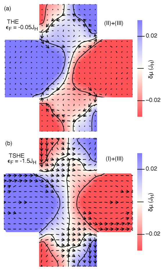
The TSHE discussed here is of similar magnitude as the SHE in broadly used Pt thin films [30]. However, the physical mechanism giving rise to the TSHE is fundamentally different from the one leading to the spin Hall effect in strong spin orbit coupled systems. In such systems, the spin Hall effect results from the topological property of the Bloch bands in momentum space. In contrast the TSHE results from the topological property of the skyrmion spin texture in real space. The real-space topology exerts opposite emergent Lorentz forces on different spins, which can induce the TSHE.
We thank the helpful discussions with Prof. Jing Shi at UCR and Dr. K. M. Masum Habib at Univ. of Virginia. This work was supported by the NSF (ECCS-1408168).
References
- [1] M. I. Dyakonov and V. I. Perel, Physics Letters A 35, 459 (1971a), ISSN 0375-9601, http://www.sciencedirect.com/science/article/pii/0375960171901964.
- [2] M. I. Dyakonov and V. I. Perel, Sov. Phys. JETP Lett. 13, 467 (1971b), http://www.jetpletters.ac.ru/ps/1587/article_24366.shtml.
- [3] A. A. Bakun, B. P. Zakharchenya, A. A. Rogachev, M. N. Tkachuk, and V. G. Fleisher, Sov. Phys. JETP Lett. (1984).
- [4] M. N. Tkachuk, B. P. Zakharchenya, and V. G. Fleisher, Sov. Phys. JETP Lett. (1986).
- [5] J. E. Hirsch, Phys. Rev. Lett. 83, 1834 (1999), http://link.aps.org/doi/10.1103/PhysRevLett.83.1834.
- [6] S. Murakami, N. Nagaosa, and S.-C. Zhang, Science 301, 1348 (2003), ISSN 0036-8075, 1095-9203, http://www.sciencemag.org/content/301/5638/1348.
- [7] J. Sinova, D. Culcer, Q. Niu, N. A. Sinitsyn, T. Jungwirth, and A. H. MacDonald, Phys. Rev. Lett. 92, 126603 (2004), http://link.aps.org/doi/10.1103/PhysRevLett.92.126603.
- [8] B. K. Nikolić, S. Souma, L. P. Zârbo, and J. Sinova, Phys. Rev. Lett. 95, 046601 (2005), http://link.aps.org/doi/10.1103/PhysRevLett.95.046601.
- [9] T. Grover and T. Senthil, Phys. Rev. Lett. 100, 156804 (2008), http://link.aps.org/doi/10.1103/PhysRevLett.100.156804.
- [10] J. Iwasaki, M. Mochizuki, and N. Nagaosa, Nature Communications 4, 1463 (2013), ISSN 2041-1723, http://www.nature.com/ncomms/journal/v4/n2/ncomms2442/metrics.
- [11] J. Wunderlich, B. Kaestner, J. Sinova, and T. Jungwirth, Phys. Rev. Lett. 94, 047204 (2005), http://link.aps.org/doi/10.1103/PhysRevLett.94.047204.
- [12] Y. K. Kato, R. C. Myers, A. C. Gossard, and D. D. Awschalom, Science 306, 1910 (2004), ISSN 0036-8075, 1095-9203, http://www.sciencemag.org/content/306/5703/1910.
- [13] J. Smit, Physica 21, 877 (1955), ISSN 0031-8914, http://www.sciencedirect.com/science/article/pii/S0031891455925969.
- [14] L. Berger, Phys. Rev. B 2, 4559 (1970), http://link.aps.org/doi/10.1103/PhysRevB.2.4559.
- [15] M. Onoda and N. Nagaosa, J. Phys. Soc. Jpn. 71, 19 (2002), ISSN 0031-9015, http://journals.jps.jp/doi/abs/10.1143/JPSJ.71.19.
- [16] N. Nagaosa, J. Sinova, S. Onoda, A. H. MacDonald, and N. P. Ong, Rev. Mod. Phys. 82, 1539 (2010), http://link.aps.org/doi/10.1103/RevModPhys.82.1539.
- [17] F. D. M. Haldane, Phys. Rev. Lett. 93, 206602 (2004), http://link.aps.org/doi/10.1103/PhysRevLett.93.206602.
- [18] G. E. Volovik, in AIP Conference Proceedings (AIP Publishing, 1989), vol. 194, pp. 136–146, http://scitation.aip.org/content/aip/proceeding/aipcp/10.1063/1.38806.
- [19] Y. Taguchi, Y. Oohara, H. Yoshizawa, N. Nagaosa, and Y. Tokura, Science 291, 2573 (2001), ISSN 0036-8075, 1095-9203, http://www.sciencemag.org/content/291/5513/2573.
- [20] P. Bruno, V. K. Dugaev, and M. Taillefumier, Phys. Rev. Lett. 93, 096806 (2004), http://link.aps.org/doi/10.1103/PhysRevLett.93.096806.
- [21] X. Z. Yu, Y. Onose, N. Kanazawa, J. H. Park, J. H. Han, Y. Matsui, N. Nagaosa, and Y. Tokura, Nature 465, 901 (2010), ISSN 0028-0836, http://www.nature.com/nature/journal/v465/n7300/full/nature09124.html.
- [22] S. Mühlbauer, B. Binz, F. Jonietz, C. Pfleiderer, A. Rosch, A. Neubauer, R. Georgii, and P. Böni, Science 323, 915 (2009), ISSN 0036-8075, 1095-9203, http://www.sciencemag.org/content/323/5916/915.
- [23] T. Schulz, R. Ritz, A. Bauer, M. Halder, M. Wagner, C. Franz, C. Pfleiderer, K. Everschor, M. Garst, and A. Rosch, Nat Phys 8, 301 (2012), ISSN 1745-2473, http://www.nature.com/nphys/journal/v8/n4/full/nphys2231.html?WT.ec_id=NPHYS-201204#ref5.
- [24] Y. Li, N. Kanazawa, X. Z. Yu, A. Tsukazaki, M. Kawasaki, M. Ichikawa, X. F. Jin, F. Kagawa, and Y. Tokura, Phys. Rev. Lett. 110, 117202 (2013), http://link.aps.org/doi/10.1103/PhysRevLett.110.117202.
- [25] N. Kanazawa, Y. Onose, T. Arima, D. Okuyama, K. Ohoyama, S. Wakimoto, K. Kakurai, S. Ishiwata, and Y. Tokura, Phys. Rev. Lett. 106, 156603 (2011), http://link.aps.org/doi/10.1103/PhysRevLett.106.156603.
- [26] A. Neubauer, C. Pfleiderer, B. Binz, A. Rosch, R. Ritz, P. G. Niklowitz, and P. Böni, Phys. Rev. Lett. 102, 186602 (2009), http://link.aps.org/doi/10.1103/PhysRevLett.102.186602.
- [27] S. X. Huang and C. L. Chien, Phys. Rev. Lett. 108, 267201 (2012), http://link.aps.org/doi/10.1103/PhysRevLett.108.267201.
- [28] S. Datta, Quantum Transport: Atom to Transistor (Cambridge University Press, Cambridge, UK; New York, 2005), 2nd ed., ISBN 9780521631457.
- [29] G. Yin, Y. Li, L. Kong, R. K. Lake, C. L. Chien, and J. Zang, arXiv:1411.7762 [cond-mat] (2014), arXiv: 1411.7762, http://arxiv.org/abs/1411.7762.
- [30] L. Liu, T. Moriyama, D. C. Ralph, and R. A. Buhrman, Phys. Rev. Lett. 106, 036601 (2011), http://link.aps.org/doi/10.1103/PhysRevLett.106.036601.