A collinear, two-color optical Kerr effect shutter for ultrafast time-resolved imaging
Harsh Purwar,1,∗ Saïd Idlahcen,1 Claude Rozé,1 David Sedarsky,2 and Jean-Bernard Blaisot1
1CORIA-UMR 6614-Normandie Université, CNRS-Université et INSA de Rouen, Campus Universitaire du Madrillet, 76800 Saint Etienne du Rouvray, France
2Applied Mechanics, Chalmers University of Technology, Hörsalsvägen 7B, 41296 Göteborg, Sweden
∗harsh.purwar@coria.fr
OCIS codes: (170.6920) Time-resolved imaging; (190.3270) Kerr effect; (280.2490) Flow diagnostics; (290.7050) Turbid media.
References and links
- [1] R. R. Alfano, S. G. Demos, and S. K. Gayen, “Advances in optical imaging of biomedical media,” Ann. NY. Acad. Sci. 820, 248–271 (1997).
- [2] L. Wang, Y. Liu, P. P. Ho, and R. R. Alfano, “Ballistic imaging of biomedical samples using picosecond optical Kerr gate,” Proc. SPIE 1431, 97–101 (1991).
- [3] M. Linne, “Imaging in the optically dense regions of a spray: A review of developing techniques,” Prog. Energ. Combust. 39, 403–440 (2013).
- [4] E. Berrocal, D. L. Sedarsky, M. E. Paciaroni, I. V. Meglinski, and M. A. Linne, “Laser light scattering in turbid media Part I: Experimental and simulated results for the spatial intensity distribution,” Opt. Express 15, 10649–10665 (2007).
- [5] C. Calba, L. Méès, C. Rozé, and T. Girasole, “Ultrashort pulse propagation through a strongly scattering medium: simulation and experiments,” J. Opt. Soc. Am. A 25, 1541–1550 (2008).
- [6] E. Berrocal, D. L. Sedarsky, M. E. Paciaroni, I. V. Meglinski, and M. A. Linne, “Laser light scattering in turbid media Part II: Spatial and temporal analysis of individual scattering orders via Monte Carlo simulation,” Opt. Express 17, 13792 (2009).
- [7] D. Newns, B. Elmegreen, X. Hu Liu, and G. Martyna, “A low-voltage high-speed electronic switch based on piezoelectric transduction,” J. Appl. Phys. 111, 084509 (2012).
- [8] M. D. Duncan, R. Mahon, L. L. Tankersley, and J. Reintjes, “Time-gated imaging through scattering media using stimulated Raman amplification,” Opt. Lett. 16, 1868–1870 (1991).
- [9] K. M. Yoo, Q. Xing, and R. R. Alfano, “Imaging objects hidden in highly scattering media using femtosecond second-harmonic-generation cross-correlation time gating,” Opt. Lett. 16, 1019–1021 (1991).
- [10] S. Idlahcen, C. Rozé, L. Méès, T. Girasole, and J.-B. Blaisot, “Sub-picosecond ballistic imaging of a liquid jet,” Exp. Fluids 52, 289–298 (2011).
- [11] L. Wang, P. Ho, C. Liu, G. Zhang, and R. Alfano, “Ballistic 2-d imaging through scattering walls using an ultrafast optical Kerr gate,” Science 253, 769–771 (1991).
- [12] R. Alfano, ed., Semiconductors probed by ultrafast laser spectroscopy (Academic, 1984, vol. II).
- [13] W. Tan, Y. Yang, J. Si, J. Tong, W. Yi, F. Chen, and X. Hou, “Shape measurement of objects using an ultrafast optical Kerr gate of Bismuth glass,” J. Appl. Phys. 107, 043104 (2010).
- [14] I. A. Heisler, R. R. B. Correia, T. Buckup, S. L. S. Cunha, and N. P. da Silveira, “Time-resolved optical Kerr-effect investigation on CS2/polystyrene mixtures,” J. Chem. Phys. 123, 054509 (2005).
- [15] J.-Y. Tong, W.-J. Tan, J.-H. Si, F. Chen, W.-H. Yi, and X. Hou, “High Time-resolved imaging of targets in turbid media using ultrafast optical Kerr gate,” Chinese Phys. Lett. 29, 024207 (2012).
- [16] S. Idlahcen, L. Méès, C. Rozé, T. Girasole, and J.-B. Blaisot, “Time gate, optical layout, and wavelength effects on ballistic imaging,” J. Opt. Soc. Am. A 26, 1995–2004 (2009).
- [17] International Standard ISO 12233, Photography - Electronic still-picture cameras - Resolution measurement, ISO, 2000.
- [18] T. Li, H. Feng, Z. Xu, X. Li, Z. Cen, and Q. Li, “Comparison of different analytical edge spread function models for MTF calculation using curve-fitting,” Proc. SPIE 7498, 74981H (2009).
Abstract
Imaging with ultrashort exposure times is generally achieved with a crossed-beam geometry. In the usual arrangement, an off-axis gating pulse induces birefringence in a medium exhibiting a strong Kerr response (commonly carbon disulfide) which is followed by a polarizer aligned to fully attenuate the on-axis imaging beam. By properly timing the gate pulse, imaging light experiences a polarization change allowing time-dependent transmission through the polarizer to form an ultrashort image. The crossed-beam system is effective in generating short gate times, however, signal transmission through the system is complicated by the crossing angle of the gate and imaging beams. This work presents a robust ultrafast time-gated imaging scheme based on a combination of type-I frequency doubling and a collinear optical arrangement in carbon disulfide. We discuss spatial effects arising from crossed-beam Kerr gating, and examine the imaging spatial resolution and transmission timing affected by collinear activation of the Kerr medium, which eliminates crossing angle spatial effects and produces gate times on the order of ps. In addition, the collinear, two-color system is applied to image structure in an optical fiber and a gasoline fuel spray, in order to demonstrate image formation utilizing ballistic or refracted light, selected on the basis of its transmission time.
1 Introduction
The non-intrusive nature of optical diagnostics make them essential tools for the study of physical systems, which are often easily perturbed. However, many real-world applications and phenomena of interest are intrinsically linked to turbid environments where light scattering and attenuation strongly limit the efficacy of optical methods. In a wide range of applications, from imaging in biological tissues [1, 2], to measurements in turbulent multiphase flows [3], key information is scrambled by the distortion imparted to the light signal as it transits the measurement volume [4]. Informative optical diagnostics in such media require detailed understanding of the light source, propagation and scattering in the measurement volume, and a detection arrangement tailored to select the meaningful parts of the transmitted light signal.
To this end, ultrafast time-gating can provide an effective means of segregating high integrity portions of the collected signal from light disturbed by scattering interactions. On average, photons which participate in more interaction events traverse a more circuitous path through the medium and are statistically more likely to be distorted or redirected from their original trajectories. This difference in optical path length results in a temporal spreading of the light intensity such that heavily distorted signal components arrive at later times. Time gating (time-based filtering) allows selection of the optical signal within a short temporal window and can be applied to separate the light that is scrambled due to multiple interactions from the optical signal that retains high-fidelity information of the object characteristics [5].
However, this requires that the time window of the gating must be short – on the order of ’s of picoseconds, or shorter. Assuming a fs input pulse and a cm turbid measurement volume, the typical transmitted pulse duration will be on the order of - ps, with most of the informative signal present in the first fs of the transmitted signal [6].
Practical electronic modulation is generally limited to nanosecond timescales, though advances in piezo-electronic devices have shown that it may be possible to gate at a few hundreds of picoseconds in specialized applications [7]. Thus, even the fastest electronically controlled gating schemes fall short of the performance demanded by most time-resolved imaging applications in turbid media.
2 Picosecond time-gated imaging
Over the past two decades, a number of nonlinear optical processes have been exploited to form sub-picosecond gating mechanisms, including stimulated Raman [8], second harmonic generation (SHG) [9, 10], and the optical Kerr effect (OKE) [11]. In terms of imaging applications, the latter approach remains the most popular in the literature and has generated renewed interest for imaging high-speed transient phenomena in scattering environments [3]. OKE gating arrangements typically achieve precise timing control by splitting the energy of an ultra-short laser pulse and adjusting the path length difference between the two beams in a pump/probe scheme to control the nonlinear interaction. The probe, or imaging pulse is used to illuminate the volume of interest, and the pump pulse is delayed and used to drive the nonlinear optical process for light selection. Thus, the temporal width of the gate window depends on the pump pulse duration and the relaxation time of the nonlinear optical effect. Figure 1 illustrates the working principle of such a pump-probe arrangement used to form an OKE time-gate using the commonly employed crossed-beam geometry. Since OKE time-gating is the focus of the present work, the operational details of this typical arrangement will be discussed in slightly more detail.


In the crossed-beam OKE gating arrangement, an off-axis gating pulse induces a time-dependent birefringence in a medium exhibiting a strong OKE response (commonly carbon disulfide) which is coupled with a polarizer positioned to fully attenuate the linearly polarized imaging beam which is aligned to propagate along the optical axis of the system. By setting the delay of the gate pulse, a selected portion of the imaging light within a short time window experiences a polarization change which allows this selected light to transit the polarizer to form an ultrashort image. Here, the polarization change experienced by the image pulse is contingent on the precise overlap of the pump and probe pulses in the Kerr medium. In this crossed-beam configuration, perfect spatial and temporal overlap of the pulses is not possible; due to the crossing angle of the beams the temporal selection carried out by the pump pulse varies across the width of the imaging beam (see Fig. 2). When the time-gate duration is on the order of a few picoseconds this spatial error is generally small, but the error becomes more significant for shorter gate times, larger imaging beam widths, or steeper crossing angles. Figure 3 shows the temporal profiles for the CS2 based optical time-gate in this arrangement for different crossing angles between the pump and the probe beams.

One approach for mitigating the spatio-temporal variation across the image beam is to reduce the crossing angle of the pump and image beam paths. Unfortunately , this increases forward-scattering of the pump pulse energy into the imaging path, and it becomes necessary to employ some additional scheme to separate the weak imaging light from the intense background. Extending this approach to its logical conclusion, if one is able to separate the pump and imaging pulses by some other means, the spatial overlap of the pulses can be maximized by reducing the crossing angle to zero.
This work presents a collinear time-gated OKE imaging arrangement in carbon disulfide (CS2), where type-I frequency doubling is employed to spectrally differentiate the imaging light from the pump pulse energy. The following sections discuss the imaging spatial resolution achieved by the collinear OKE system and the light transmission timing resulting from collinear activation of the Kerr medium. This system is then applied to two imaging situations where the OKE gate is adjusted to capture refracted and ballistic light images in order to demonstrate the light selection capabilities of the two-color system.
3 Collinear OKE time-gating
Figure 4 shows a schematic of the collinearly pumped OKE time-gated imaging system used in this work. The femtosecond laser pulse used to generate the image and pump pulses is supplied by a regenerative amplifier (Coherent Libra) seeded by a mode-locked Titanium-Sapphire oscillator (Coherent Vitesse). This system generates laser pulses with pulse width fs centered at wavelength of nm and a peak power of GW at a kHz repetition rate. Each laser pulse from the amplifier is directed into the optical system where it is split into pump and imaging beam paths by a : beamsplitter.
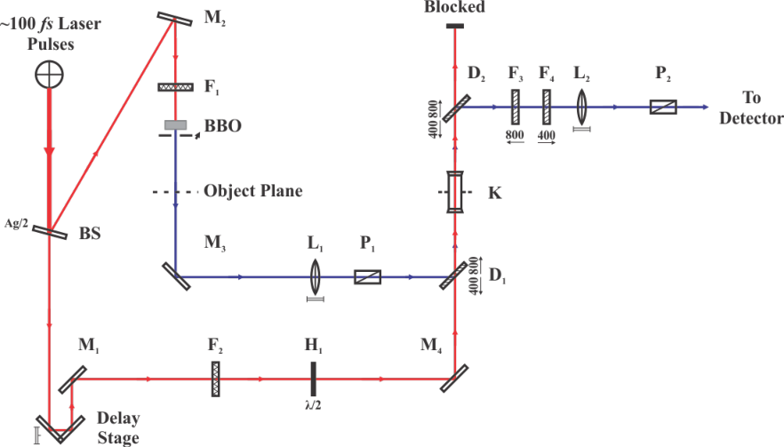
The imaging pulse passes through an ND filter, and is frequency doubled by means of type-I second harmonic generation (SHG) in a beta-barium borate (BBO) crystal to produce imaging light with a center wavelength of 400 nm. The conversion efficiency of the SHG process is on the order of . After interaction with the measurement volume the imaging pulse is directed through a polarizer, and on to the CS2 cell by a dichroic mirror. This dichroic element transmits the nm pump pulse while reflecting the nm imaging pulse, effectively combining the image and pump beam paths to enable collinear propagation into the Kerr medium. Here, the collinear arrangement was selected to allow optimal spatial overlap of the pulses within the CS2.
The Kerr medium (CS2) was placed at the image plane of the lens so that the spatial frequencies are gated equally through the optical gate, thereby producing an image with better resolution compared to the case where the Kerr medium is place at the Fourier plane of . Although, this requires the switching or pump beam to be more homogeneous and large enough to encompass the image formed by at its image plane. This can be achieved easily in this collinear configuration since the temporal characteristics of the optical gate do not depend on the spatial size of the switching beam. In case the switching beam is not homogeneous throughout in space, the resulting time-gated images would also not be transmitted homogeneously through the optical gate.
The pump pulse is directed from the beamsplitter through a computer controlled delay stage with a minimum step-size of m, corresponding to a minimum temporal delay step of fs. The time delay imparted by the delay stage is adjusted to reconcile the path lengths of the pump and probe beam paths such that the pump and imaging pulses arrive at the Kerr medium simultaneously, allowing careful overlap of the pulses in space and time. A neutral density (ND) filter is used to set the power of the pump beam and a half waveplate is used to rotate its polarization with respect to the imaging light. This adjustment is necessary to maximize the induced birefringence in the Kerr medium to fully utilize the transmission efficiency of the time-gate. The transmission of imaging light through the OKE gate is given by [12]:
where is the phase shift experienced by the imaging pulse, and is the angle between the imaging and pump beam polarization states.
After interaction with the Kerr medium, the imaging beam path continues through a second dichroic mirror and band pass filter to eliminate the nm pump light, and through a bandpass filter designed to transmit the nm imaging light. The filtered imaging light then crosses a second polarizer aligned to block the original polarization of the imaging pulse (before interaction with the Kerr medium) to arrive at the detector forming a time-gated image.
Note that the pump beam nm (derived directly from the laser beam) and probe beam nm (frequency doubled using BBO crystal) are chosen in this fashion and not the other way round because the average power (or energy) required to introduce a significant OKE in the Kerr medium (CS2) would not be enough due to the losses during SHG or otherwise an even higher power fs laser source would be required. Also, it has been observed that the high-power laser beam at nm tends to damage the CS2 by forming a brown precipitate over a very short duration of time. It is also for this reason that the CS2 should not be placed at the Fourier plane of the lens in this dual-color configuration.
The detector used in the imaging measurements was an EM-CCD camera (Hamamatsu C9100-02). Supplementary intensity measurements and scans for system characterization were carried out using a high-resolution power meter (Ophir, Nova-II).


Most of the OKE time-gated imaging setups discussed in the literature employ a crossed-beam geometry in order to spatially separate the pump and image light [13, 14, 15, 16]. The spatial overlap of the pump beam on the probe beam covers an area inside the Kerr medium corresponding to a constant time. This solves the problem of mixing of spatial and temporal information carried by the probe as it passes through the optical gate. Hence, the output images for various delays between the pump and the probe pulses have spatial information pertaining to the same time event in this collinear approach. Figure 5 shows the average line profiles of the probe beam through the optical time-gate with non-collinear and collinear incidence of the incoming pump and probe beams at the Kerr medium for different delay between them. Since the overlap between the pump and probe pulses when incident collinearly is uniform in space, there is no shift in the intensity profile with delay in this case. This makes it more suitable for applications in ultrafast time gated imaging, since the information carried by the probe is not corrupted as it passes through the optical gate.
4 Results
4.1 Characterization of the optical time-gate
The spatial resolutions and temporal profiles for the proposed OKE based time-gate presented above were measured with liquid carbon disulfide (CS2) as Kerr medium known to produce measurable Kerr effect due to its high non-linear refractive index (n2). Figure 6 shows the temporal profile of the optical time-gate for three different thicknesses of the CS2 cell - 10 mm, 2.0 mm and 1.0 mm, without any object/sample placed in the probe beam’s path. The gate duration (time for which the optical time-gate is open or allows a part of the probe pulse to pass through the crossed polarizer arrangement) is least in case of a 1.0 mm CS2 cell.

The dependence of the optical gate duration on the thickness of the Kerr medium is not observed in classical single wavelength OKE-based time-gates. Indeed, in this case, the pump and the probe beams intersect within the Kerr medium, overlapping over a constant temporal width, in and out of the medium as they always travel with the same speeds. In the proposed dual wavelength configuration, since the wavelengths of both the beams are different ( nm for probe and nm for pump), they propagate with different group velocities () inside the Kerr medium (). So, even if a delay is imposed between these pulses outside the Kerr medium, the pump pulse catches up with the probe while traveling through the medium. An overlap occurs for a short duration and induces a polarization change of the probe beam, resulting in its transmission through the second polarizer, giving one point of the curves plotted in Fig. 6. The range of possible overlapping is limited by the thickness of the Kerr medium. Nevertheless, a too thin Kerr medium leads to a poor efficiency of the optical time-gate. A more detailed discussion on the use of two wavelengths in optical gating may be found in ref. [16]. Figure 6 shows that a cell thickness of mm is a good compromise: it gives a temporal resolution of ps (full width at half maximum) and allows one to recover the relaxation time of CS2.


Apart from the temporal resolution, another critical parameter for an optical gate is the quality of the measured images, and particularly spatial resolution, which may be estimated using the normalized modulation transfer function (MTF). The MTF for the present optical setup was measured using slanted-edge method (ISO 12233 standard for MTF measurement of electronic still-picture cameras [17]). The MTF and edge-spread function (ESF), are related as follows,
| (1) |
where is the spatial frequency in lines/mm, is the abscissa along an axis orthogonal to the slanted edge (or knife). In other words, MTF is the Fourier transform of the derivative of the ESF, which is also the line-spread function. It should be noted that while calculation of MTF from the over-sampled ESF data, the differentiation along the slanted edge is very sensitive to the high-frequency noise and in order to avoid amplifying this noise during the computation of the derivative, the averaged over-sampled ESF is fitted using the Logistic (Fermi) function [18],
| (2) |
where , , and are the desired fit parameters. Figure 7 shows the fitted ESF and normalized MTF calculated using eq. (1) for dual-color, collinear configuration with the Kerr medium (CS2) placed at the image plane of the lens . For comparison Fig. 7(b) also shows the normalized MTF for the traditional single-color, non-collinear configuration with CS2 placed at the Fourier plane of . The achievable imaging spatial resolution from the MTF curve (inverse of Nyquist frequency) with CS2 as the Kerr medium placed at the image plane of for collinear configuration was found to be lines/mm and for the non-collinear configuration with the same Kerr medium placed at the Fourier plane of it was found to be lines/mm.
4.2 Examples of application
Beyond the development and characterization of the proposed optical time-gate setup, an application of the technique for ballistic imaging is shown for different objects. Figure 8 shows images of a micro-structured optical fibre LMA-25 from NKT Photonics with an overall average diameter of m (with coating) obtained using mm CS2 optical gate. In Fig. 8(a), the delay line is adjusted to select only ballistic light, i.e. light which has not interacted with the object. When the delay between the probe and pump is increased, ballistic light disappears and the hidden microstructures inside the optical fibre as in Fig. 8(b) are revealed by the refracted light, though the intensity of the refracted light is very low as compared to the ballistic light.


Figure 9 shows an application of the mm CS2 optical time-gate to a liquid spray, produced by a single orifice injector (diameter m). The injection pressure was MPa, and the resulting velocity about m/s. The fluid used in the measurements was a calibration oil (Shell NormaFluid, ISO 4113) with thermophysical properties similar to that of diesel fuel, and a refractive index of . The images were taken close to the injector and the first millimeter from the nozzle is visible. Again, the delay between the pump and the probe was adjusted so that detection time coincides with ballistic light Fig. 9(a). When the delay was increased, ballistic light disappeared and a small fluctuating bright line appeared at the center of the jet, corresponding to the refracted light (Fig. 9(b)), showing that at a few hundreds of micrometers from the nozzle, the liquid jet shape is still close to a cylinder.

It should be noticed that the gate duration for mm CS2 based time-gate is about ps, and seems not short enough to separate the ballistic and the refracted light signals: the m diameter corresponds to a fs time delay between them. However, the separation of the refracted and the ballistic light signals is possible even by a time gate of much larger duration, by imposing an appropriate delay between the pump and the probe pulses (Fig. 10). Since the ballistic light is much more intense compared to the refracted light, for an appropriate delay (blue, solid line curve of Fig. 10) even a small transmission through the time-gate is sufficient to produce a high contrast ballistic image at the detector. The contribution of the refracted light becomes negligible at this delay. And then by preciously increasing the delay between the pump and the probe pulses (blue, dashed line curve of Fig. 10), it is possible to obtain a similar image with contribution mainly from the refracted light.
5 Conclusions
A collinear, dual wavelength OKE based time-gate has been proposed to overcome the drawbacks of the classical single wavelength, crossed-beam arrangement. The idea of using different wavelengths for pump and probe beams reduces the noise due to the scattering of the high power pump beam towards the detector. It opens the possibility to combine the pump and the probe pulses into a collinear beam, removing the mixing of spatial and temporal information on the images. The achievable spatial resolution estimated from MTF calculation was found to be lines/mm with Kerr medium (CS2) placed at the image plane of the lens . The time resolution was about ps, limited by the relaxation time of CS2. The developed optical time-gate was found to be capable of separating ballistic and refracted light from a static object (a microscopic optical fiber) and a dynamic one (a liquid spray).
Acknowledgments
This work was supported by NADIA-Bio program, with funding from the French Government and the Haute-Normandie region, in the framework of the Moveo cluster (”private cars and public transport for man and his environment”).