Signature of snaking states in the conductance of core-shell nanowires
Abstract
We model a core-shell nanowire (CSN) by a cylindrical surface of finite length. A uniform magnetic field perpendicular to the axis of the cylinder forms electron states along the lines of zero radial field projection, which can classically be described as snaking states. In a strong field, these states converge pairwise to quasidegenerate levels, which are situated at the bottom of the energy spectrum. We calculate the conductance of the CSN by coupling it to leads, and predict that the snaking states govern transport at low chemical potential, forming isolated peaks, each of which may be split in two by applying a transverse electric field. If the contacts with the leads do not completely surround the CSN, as is usually the case in experiments, the amplitude of the snaking peaks changes when the magnetic field is rotated, determined by the overlap of the contacts with the snaking states.
pacs
73.63.Nm, 73.22.DjIntroduction.—The transport properties of semiconductor nanostructures subjected to an external magnetic field remains a topic of intense research to this day. A recently conceived heterostructure is the core-shell nanowire (CSN) [1, 2, 3, 4]. It consists of a thin layer (shell) surrounding a core in a tubular geometry, which may be engineered such that carriers are confined to the shell, e. g. a conductive InAs shell surrounding a GaAs core [5]. By piercing them with a longitudinal magnetic flux, CSNs have been applied to study the Aharonov-Bohm effect [6, 7, 8], which manifests as flux-periodic oscillations in e. g. magnetoconductance [3, 9].
Fascinating physics also manifests if a perpendicular magnetic field is applied. In this case, orbital electron motion is governed by the radial field projection, such that the magnetic field becomes effectively inhomogeneous. Hence, such systems are comparable to the older topic of a planar electron gas in an inhomogeneous magnetic field [10, 11, 12, 13]. In Ref. 14, transport measurements were performed on segments of cylinders, and a notable asymmetry in the magnetoresistance was observed with respect to field orientation. Furthermore, simulations of a cylindrical electron gas immersed in a perpendicular field predicted the formation of states with distinct characteristics, localized in different regions around the circumference [15, 16]. Propagating states tend to be localized in narrow channels, where the magnetic field is parallel to the surface, laterally confined by a Lorentz force. On the other hand, states with small wave numbers are condensed into a highly-degenerate Landau level, localized in regions where the field and surface are perpendicular, similar to a planar two-dimensional electron gas (2DEG). In Ref. 17, a semiclassical analysis was applied to identify these states as snaking and cyclotron states, respectively. More recent work saw the simulation of CSNs with hexagonal cross sections, which is more realistic than a circular one. The same qualitative behavior was observed, but with added localization effects due to the corners [18, 19]. Indeed, in Ref. 19, magnetoconductance calculations are presented, but to our knowledge, the manifestations of snaking and cyclotron states in the transport characteristics of CSNs have not been reported.
In this paper, we calculate the electron states on a cylindrical surface of finite length, immersed in a perpendicular magnetic field, and analyze the transport signatures of said states by coupling the cylinder to leads using a Green’s function method. Emphasis is on the snaking states and how they manifest in transport. We probe the experimentally relevant effects of a nonzero shell thickness, and of nonuniform coupling by allowing the contacts with the leads to connect to the cylinder over restricted angular intervals, and/or to its interior. At large magnetic fields, the states essentially fall into three categories, each located in a different part of the cylinder, namely cyclotron states condensed into a Landau level, edge states localized at the cylinder ends, and snaking states, which are the energetically lowest ones. The transport signature of each state type is interpreted in terms of its distribution in the finite system and overlap with the contacts. In particular, there is a visible asymmetry in the snaking conductance peaks, which appear at low chemical potential, depending on whether the contacts overlap with the snaking states or not, which in practice can be changed by rotating the magnetic field.

Model.—The system under consideration consists of noninteracting electrons confined to a cylindrical surface of radius and length , narrow enough to be treated as infinitely thin, with hard-wall boundary conditions imposed at the edges. In a transverse magnetic field , electron orbital motion is governed by the radial projection . It is nonuniform around the cylinder circumference, breaking the rotational symmetry of the system, as is clear from the vector potential . Figure 1 shows a sketch of the system. The single-electron Hamiltonian is
| (1) |
where the orbital part is the kinetic energy term
| (2) |
with , and the effective electron mass . Electron spin is included through the Zeeman term
| (3) |
where is the effective electron g-factor and the free electron mass. The orbital part of the time-independent Schrödinger equation, , is diagonalized in the basis of eigenstates of with T.
To evaluate the transport properties of the finite cylinder, we couple it to two leads via contacts, shown schematically in Fig. 1, and apply a Green’s function formalism to calculate the phase-coherent conductance in the linear-response regime [20, 21, 22, 23, 24, 8]. It follows from the spin-resolved Landauer formula
| (4) |
where is the Fermi-Dirac function, evaluated at the chemical potential and temperature , both of which are assumed constant throughout the coupled system. Here, is the inverse retarded Green’s operator of the coupled central cylinder, where the left () and right () leads enter through the self-energies , which are generally complex and result in level broadening in the central part, characterized by the operators [20, 25]. The operators in Eq. (4) act on the central system subspace and are constructed in the basis of eigenstates of [Eq. (1)]. By assuming coupling terms between the central part and the leads at each junction, the self-energies assume the form
| (5) |
where couples lead to the finite cylinder and is the inverse retarded Green’s operator of the uncoupled lead, described by the Hamiltonian . While states in the leads and the central part have no spatial overlap, the transmission of electrons is facilitated through the coupling terms in the self-energy matrix elements by introducing a nonlocal coupling kernel, which in turn models the contacts. Applying in Eq. (5) the closure relation for the isolated lead eigenstates, which satisfy , one obtains the matrix element
| (6) |
In coordinate representation, the overlap matrix elements are [, ]
| (7) |
where the two spatial integrals, which extend over the finite cylinder () and lead , couple through the kernel . We use a kernel which decays exponentially with distance from the junction, and may couple the leads to the central part uniformly over the circumference or over restricted angular intervals (Fig. 1), the latter of which models the nonuniform application of contacts in experiment. A possible shift of the kernel away from the cylinder edges is also included, to model the application of contacts to the interior, as is typical in experiment [3, 9]. In this case, only the central system part of the kernel is shifted, leaving the kernel overlap with states in the leads unchanged. Technically, the leads are taken as semi-infinite cylindrical continuations of the central part with hard-wall boundary conditions imposed at the junctions with the finite system [8]. However, we limit ourselves to weak coupling, which ensures that the particular form of the kernel and the leads is not paramount, as should be governed by the properties of the finite cylinder itself, i. e. by in Eq. (1). The present model for the contacts has been used to qualitatively replicate experimental results [8]. Alternative models, e. g. Ref. 26, would only result in a minor change in level broadening.
Results and discussion.— Let nm and nm for an aspect ratio , such that multiple axial levels enter the spectrum per angular mode. Material parameters are taken for InAs, i. e. and . In this work, we neglect the effects of surface defects and impurities. This is a reasonable approximation, because the measured mean free path of InAs surface inversion layers is of the order nm, and the cylinder under consideration is therefore close to the ballistic limit [27, 28]. From a semiclassical point of view [10, 17], lateral confinement by the Lorentz force is expected to produce snaking electron states where the radial field projection vanishes (), while cyclotron states condensed into a Landau level are expected where the radial projection is maximum ( and ). In these regions, is parallel and perpendicular to the cylinder surface, respectively, and we refer to them as the snaking and cyclotron regions. The two types of states become localized in their respective regions and clearly discernible if .
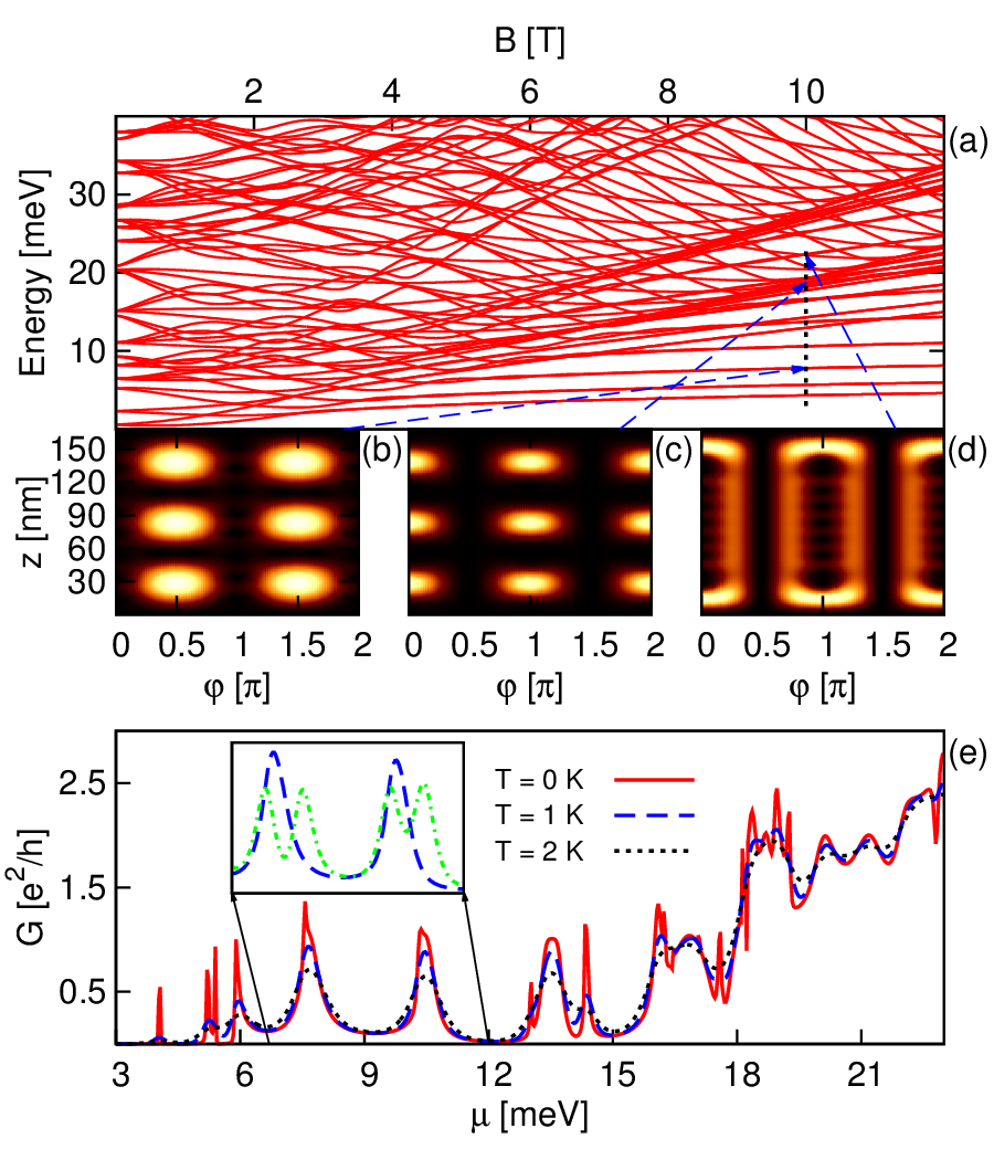
Figure 2(a) shows the spectrum of the finite cylinder, uncoupled to leads, as a function of . At large (e. g. T), the electron states roughly fall into three categories. The energetically lowest states converge pairwise into quasidegenerate levels, all of which are localized in the snaking regions, as exemplified in Fig. 2(b), which shows the probability density of one such state. Hence, we identify them as snaking states. The quasidegeneracy arises due to the symmetry between the snaking regions, as the magnetic confinement does not distinguish between them. The energy difference between the quasidegenerate snaking states is very small, unresolvable along the vertical dotted line in Fig. 2(a), and it tends to vanish with increasing magnetic field strength. The quasidegeneracy can be lifted e. g. by applying a transverse electric field, to explicitly break the symmetry between the snaking regions. A similar, but exact, degeneracy arises on a CSN of infinite length, where the degenerate states correspond to longitudinal propagation in opposite directions along the cylinder axis [16]. Moving up in energy in the spectrum, the density of states rises abruptly in a narrow energy interval. The relevant states are localized in the cyclotron regions, as the example in Fig. 2(c) illustrates. Accordingly, these are cyclotron states condensed into a Landau level [15, 18, 16]. Observe that the Landau level is split into spin up and down branches by the Zeeman term. If spin splitting is neglected, its energy approximately coincides with the lowest Landau level of a planar 2DEG, . The final category consists of states that are all primarily localized at the cylinder ends, as the example in Fig. 2(d) shows, and hence we refer to them as edge states. Their energies are woven into a net-like structure, reminiscent of the flux-periodic oscillations that arise when wave functions enclose a magnetic flux [29, 30]. Here, the net-like structure manifests because the electron wave functions enclose a magnetic flux perpendicular to the curved cylinder surface. Lastly, we mention that if Zeeman splitting is neglected, the aforementioned categories become segregated in energy, such that the snaking states are energetically lowest, followed by the Landau level, and then by the edge states. Here, this separation is lost because of the large g-factor in InAs, but it would still be present in a material with a smaller g-factor, e. g. GaAs. Regardless, the energetically-lowest states are still snaking states, with the spin down branch setting in around meV at T, among the snaking states of the spin up branch.
The various state categories previously discussed manifest differently in transport. In Fig. 2(e), we show [Eq. (4)] with T as a function of at various temperatures. The corresponding energy range is marked with a vertical dotted line in Fig. 2(a). Roughly, peaks when intersects with an energy level of the finite cylinder, with level broadening and energy shift arising due to the self-energies , both of which are small ( meV) because the systems are weakly coupled. Another effect is thermal broadening due to smearing of the Fermi function, as the conductance curves illustrate. Sweeping through the values of , we see a number of conductance peaks at low energies corresponding to the snaking states in the finite cylinder ( meV). They vary in size and shape because the corresponding states on the finite cylinder couple differently to the contact kernel, resulting in different self-energy matrix elements, and hence level broadening. Here, nm, and the contacts are applied uniformly over the cylinder circumference ( in Fig. 1), so it is primarily the difference in the states’ longitudinal distribution that causes different broadening. For example, the first peak ( meV) corresponds to a state which is localized around the cylinder center. Hence, it has significantly less overlap with the contact kernel, which is localized at the edges, than the state corresponding to the peak around meV, the distribution of which is similar to the one in Fig. 2(b). As discussed in the preceding paragraph, each snaking conductance peak arises due to a pair of quasidegenerate snaking states in the closed system. In Fig. 2(e), the inset shows how two of the snaking peaks ( K) are affected by a weak electric field of strength eV/nm, oriented along the axis. This breaks the symmetry between the snaking regions, splitting the quasidegenerate snaking states in energy, which in turn splits each conductance peak in two by an amount proportional to the electric field strength, as the dash-dotted curve shows. Around meV, the spin up Landau level sets in, resulting in a sharp increase in . The Landau level is furthermore characterized by a sequence of narrow conductance peaks at K, each corresponding to a cyclotron state, which are washed out and combined by thermal broadening at and K. Above the Landau level ( meV), we observe a number of peaks that are significantly more broadened than the lower-energy peaks, even at K. These correspond to the edge states in the closed system, which are primarily localized at the cylinder ends [e. g. Fig. 2(c)]. Accordingly, such states overlap more with the contacts than the other types, and therefore their broadening is more substantial.
The assumption of an infinitely narrow surface is an idealization of the shell, which in reality has some thickness. To gauge the validity of our model, let us consider a shell with nonvanishing thickness . The kinetic energy term is the same as in Eq. (2), but with replaced by the radial coordinate , and the added term . Here, is the canonical radial momentum operator, with . Imposing hard-wall boundary conditions at and , we diagonalize the radial part of the Hamiltonian in the basis of eigenstates of , namely
| (8) |
whose eigenvalues are the familiar infinite square well energies. The thickness is implemented in the leads analogously. Intuitively, an infinitely narrow surface should be a good approximation if the lowest radial mode in Eq. (8) dominates in the energy range of interest, namely . We performed calculations with chosen such that the mean radius is equivalent to given above. Our results (not shown here) with nm and nm show the same qualitative behaviour as observed in Fig. 2. For the former, , which is realistic from an experimental point of view [9, 31]. In both cases, the energy difference between the two lowest states in Eq. (8) is much larger than ( meV at T), such that the lowest radial mode is dominant. Indeed, the relevant states are all localized around , and snaking and cyclotron states remain spatially separated. Furthermore, the energy spectra are nearly indistinguishable from the case with an infinitely narrow shell, and although there are minor differences in the finer structure of individual conductance peaks, the same trends as in Fig. 2(e) are present, namely isolated snaking peaks followed by the onset of the spin split Landau level.

The transport signature of a particular state is primarily determined by its overlap with the coupling kernel. Furthermore, snaking, cyclotron, and edge states are all principally localized in their respective regions on the finite cylinder. Combining this with a restricted application of the contacts, over limited parts of the circumference, we can tailor the transport signatures of the various types of states. Figure 3 shows the conductance of the coupled system as a function of with T and K. The values are chosen such that the conductance peaks correspond to snaking states, whose energies in the closed system are marked with vertical dash-dotted lines [see also Fig. 2(a)]. Both leads are coupled identically to the central part with nm, over an angular interval , centered at a cyclotron region (solid line) or a snaking region (dashed line). By parity invariance, it does not matter to which of the two snaking or cyclotron regions the contacts are applied. The conductance peaks shown are significantly more pronounced in the latter case than in the former, because the snaking states’ overlap with the coupling kernel is greater when the contacts connect to a snaking region than when they connect to a cyclotron region, resulting in a visible asymmetry between the two cases. Similarly, the cyclotron states are more prominent if the contacts are applied to a cyclotron region (not shown).
Typically, contacts are not applied to the sample edges as we have assumed, but to the interior [3, 9]. In Fig. 3, the dotted curve shows obtained with nm, using contacts placed over a snaking region, and the same parameters as in the preceding paragraph. Intuitively, the increased overlap with states in the central part should yield larger self energies, resulting in more prominent level broadening and energy shift. Indeed, the peaks are more broadened and shifted, as compared to the dashed curve, which is identical but with nm. Nevertheless, the two curves exhibit the same qualitative behavior.
Conclusions.— We have performed calculations for electrons on a cylindrical surface, to simulate a CSN, and seen the formation of snaking, cyclotron, and edge states in a large, perpendicular magnetic field. Each state type has a different transport signature, with broadening primarily governed by its overlap with the contacts. In particular, the snaking states manifest as peaks at low chemical potentials. Each snaking peak can be split in two by breaking the symmetry between the two snaking regions, e. g. with a transverse electric field. Such a field can be created with lateral gates attached to the CSN. However, in a realistic system, it is possible that nonuniform application of contacts around the nanowire could induce intrinsic fields, which might break the symmetry between the snaking regions, splitting the snaking conductance peaks, even in the absence of a transverse electric field. Regardless, a weak electric field might still be used to tune the spacing between the peaks, possibly even to recombine them. Our results hold even in the presence of a nonzero shell thickness. We have furthermore shown that if the contacts only connect to restricted parts of the nanowire, the snaking conductance peaks exhibit a pronounced asymmetry with varying contact placement along the circumference, depending on the snaking states’ overlap with the contacts. Moving the contacts in such a manner relative to the snaking regions may be achieved experimentally by rotating the magnetic field in the plane perpendicular to the axis of the cylinder.
Acknowledgements.
We thank Thomas Schäpers for enlightening discussions. This work was supported by the Research Fund of the University of Iceland and the Icelandic Research and Instruments Funds.References
- [1] Y. Li, F. Qian, J. Xiang, and C. M. Lieber, Materials Today 9, 18 (2006).
- [2] C. Thelander, P. Agarwal, S. Brongersma, J. Eymery, L. Feiner, A. Forchel, M. Scheffler, W. Riess, B. Ohlsson, U. Gösele, and L. Samuelson, Materials Today 9, 28 (2006).
- [3] M. Jung, J. S. Lee, W. Song, Y. H. Kim, S. D. Lee, N. Kim, J. Park, M.-S. Choi, S. Katsumoto, H. Lee, and J. Kim, Nano Letters 8, 3189 (2008).
- [4] B. M. Wong, F. Léonard, Q. Li, and G. T. Wang, Nano Letters 11, 3074 (2011).
- [5] T. Rieger, M. Luysberg, T. Schäpers, D. Grützmacher, and M. I. Lepsa, Nano Letters 12, 5559 (2012).
- [6] Y. Tserkovnyak and B. I. Halperin, Phys. Rev. B 74, 245327 (2006).
- [7] V. N. Gladilin, J. Tempere, J. T. Devreese, and P. M. Koenraad, Phys. Rev. B 87, 165424 (2013).
- [8] T. O. Rosdahl, A. Manolescu, and V. Gudmundsson, Phys. Rev. B 90, 035421 (2014).
- [9] O. Gül, N. Demarina, C. Blömers, T. Rieger, H. Lüth, M. I. Lepsa, D. Grützmacher, and T. Schäpers, Phys. Rev. B 89, 045417 (2014).
- [10] J. E. Müller, Phys. Rev. Lett. 68, 385 (1992).
- [11] I. S. Ibrahim and F. M. Peeters, Phys. Rev. B 52, 17321 (1995).
- [12] P. D. Ye, D. Weiss, R. R. Gerhardts, M. Seeger, K. von Klitzing, K. Eberl, and H. Nickel, Phys. Rev. Lett. 74, 3013 (1995).
- [13] S. D. M. Zwerschke, A. Manolescu, and R. R. Gerhardts, Phys. Rev. B 60, 5536 (1999).
- [14] K.-J. Friedland, R. Hey, H. Kostial, A. Riedel, and K. H. Ploog, Phys. Rev. B 75, 045347 (2007).
- [15] G. Ferrari, A. Bertoni, G. Goldoni, and E. Molinari, Phys. Rev. B 78, 115326 (2008).
- [16] A. Manolescu, T. Rosdahl, S. Erlingsson, L. Serra, and V. Gudmundsson, The European Physical Journal B 86, 445 (2013).
- [17] S. Bellucci and P. Onorato, Phys. Rev. B 82, 205305 (2010).
- [18] G. Ferrari, G. Goldoni, A. Bertoni, G. Cuoghi, and E. Molinari, Nano Letters 9, 1631 (2009).
- [19] M. Royo, A. Bertoni, and G. Goldoni, Phys. Rev. B 87, 115316 (2013).
- [20] S. Datta, Electronic Transport in Mesoscopic Systems (Cambridge University Press, 1995).
- [21] M. Brandbyge, J.-L. Mozos, P. Ordejón, J. Taylor, and K. Stokbro, Phys. Rev. B 65, 165401 (2002).
- [22] K. S. Thygesen, M. V. Bollinger, and K. W. Jacobsen, Phys. Rev. B 67, 115404 (2003).
- [23] T. Tada, M. Kondo, and K. Yoshizawa, The Journal of Chemical Physics 121, 8050 (2004).
- [24] M. Paulsson, (2008), arXiv:cond-mat/0210519v2 [cond-mat.mes-hall].
- [25] S. Kurth, G. Stefanucci, C.-O. Almbladh, A. Rubio, and E. K. U. Gross, Phys. Rev. B 72, 035308 (2005).
- [26] V. Gudmundsson, C. Gainar, C.-S. Tang, V. Moldoveanu, and A. Manolescu, New Journal of Physics 11, 113007 (2009).
- [27] T. Matsuyama, R. Kürsten, C. Meißner, and U. Merkt, Phys. Rev. B 61, 15588 (2000).
- [28] S. Chuang, Q. Gao, R. Kapadia, A. C. Ford, J. Guo, and A. Javey, Nano Letters 13, 555 (2013).
- [29] Y. Aharonov and D. Bohm, Phys. Rev. 115, 485 (1959).
- [30] N. Byers and C. N. Yang, Phys. Rev. Lett. 7, 46 (1961).
- [31] T. Wenz, M. Rosien, F. Haas, T. Rieger, N. Demarina, M. I. Lepsa, H. Lüth, D. Grützmacher, and T. Schäpers, Applied Physics Letters 105, 113111 (2014).