The silicon matrix for the prototype of the Dark Matter Particle Explorer
Abstract
A new generation detector for the high energy cosmic ray - the DAMPE(DArk Matter Particle Explorer) is a satellite based project. Its main object is the energy measurement of the cosmic ray nuclei from 100GeV to 100TeV, the high energy electrons and gamma ray from 5GeV to 10TeV. A silicon matrix detector described in this paper, is employed for the sea level cosmic ray energy and position detection while the prototype testing of the DAMPE. It is composed by the 180 silicon PIN detectors, which covers an area of . The primary test result shows a good MIPs discrimination.
Keywords:
Dark matter , silicon matrix , cosmic ray1 Introduction
With the results of AMS-02[1], ATIC[2], PAMELA[3] and FERMI[4], more and more proofs pointed the electron excess of cosmic electrons. With a requirement of higher and more precise energy measurement, a dark matter search satellite project DAMPE has been put forward.
The main scientific objective of DAMPE is to measure electrons and photons with much higher energy resolution and energy reach than achievable with existing space experiments in order to identify possible Dark Matter signatures. It has also great potential in advancing the understanding of the origin and propagation mechanism of high energy cosmic rays, as well as in new discoveries in high energy gamma astronomy.
There are four sub-detector in the DAMPE system, the plastic scintillator(PSD), the silicon tracker(STK), the BGO electromagnetic calorimeter(BGO) and the neutron detector.(see Figure 1)

The plastic scintillator and silicon tracker are employed to charge particles’ discrimination and reconstruction the track. The silicon tracker with tungsten convertors can also distinguish the gamma ray and electrons. The STK is followed by an imaging calorimeter of about 31 radiation lengths thickness, made up of 14 layers of BGO bars in a hodoscopic arrangement. A layer of neutron detectors is added to the bottom of the calorimeter for the proton/electron discrimination. The total thickness of the BGO calorimeter and the STK correspond to about 33 radiation lengths, making it the deepest calorimeter ever used in space.
For electrons and photons, the detection range of the DAMPE is 5 GeV - 10 TeV, with an energy resolution of about 1% at 800 GeV. For cosmic rays, the detection range is 100 GeV - 100 TeV, with an energy resolution better than 40% at 800 GeV. The geometrical factor is about for electrons and photons, and about for cosmic rays. The angular resolution is 0.1∘ at 100 GeV.
During the DAMPE prototype testing, a silicon matrix built by the Institute of High Energy Phsics(IHEP), the Chinese Academy of Sciences(CAS), serves as the silicon tracker. Followed chapters describe the details of the silicon matrix construction and test.
2 The detector structure
2.1 the silicon matrix
In accordance of the required sensitive area, the matrix is composed of 180 large area silicon PIN detectors(see Figure 2 d). Each of them has an active area of and 0.5mm thickness. The full depletion voltage for the selected detectors is 40 V, while the operation voltage is 60 V. The measure leak current of detectors is under 100 nA. The detector after selection is attached on a ceramic chip in a Kovar package.

To achieve a better detection efficiency of incident particles over 60∘ , every detector has a small overlap to the neighbor ones.(see Figure 2 c) The overlap is determined by the calculation and confirmed by the fast simulation.
While the assembling, the detector is fixed on the readout PCB and an aluminum frame via four screws. The detectors on top and on bottom are combined in two layers respectively. Figure 3 shows the photograph of the top layer matrix. As this structure, the silicon matrix can achieved an active area up to .

2.2 the electronics
As shown in Figure 4, the readout electronics system of the matrix consists an ASIC PCB and a control PCB. A aluminum box is employed to shield the detectors and the front-end electronics(FEE) from the surrounding light and the electro-magnetic interference. A VA140 readout PCB is mounted on the back of each layer. The signals through the flex are read out by six VA140 chips, which are controlled by an FPGA. The DAQ communicated with the computer via the USB bus.
The VA140 is a 64-channel, low noise and high dynamic range charge measurement ASIC designed by IDEADS (Norway)[5]. It is an updated version of the VA64HDR9A ASIC, which is used by AMS[6], implemented in 0.35um process for lower power consumption and better radiation tolerance. Each channel contains a charge sensitive preamplifier, a shaper circuit and a sample-hold circuit. Since the primary package can only afford 32 pins output, we used the half of all the 64 channels to readout signals in every VA140.

The control board is used for the VA140 control, the analog signal digitalization and the data communication. It contains a power module (the HV and the regulator), a controlling FPGA(XC3S500E), a 14-bit 3MSPS ADC(AD9243) and a USB interface chip(CY7C68013). A level shift circuit from to is used in the control board, due to the mismatched level voltage between the FPGA and the VA140.
The DAQ is based on a LabWindows GUI online software, while the offline data analysis is undertaken with the ROOT framework. In the test of electronics, An 100Hz random trigger is induced in to acquire the pedestals of every channel. We get an average noise of the channels is about 0.35 fC.
3 The cosmic ray test
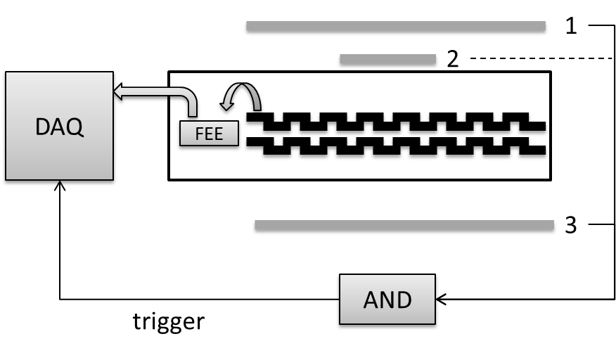
There are two requirements of this matrix, giving the particle charge information and the track reconstruction. The test in laboratory is completed with the sea level cosmic ray. In this test, we can get the unit charge response(MIPs) and an approximately position distribution.
A simple telescope system is set up for the test, which can be seen in Figure 5. The grey box labeled 1,2,3 stand for plastic scintillators. The area of scintillator 1 and 3 is , which covers the whole surface of the matrix. The silicon matrix is placed in the middle of the plastic scintillators. When the incident particle pass through, this two plastic scintillators give the coincidence trigger to the DAQ. With a long time test, the MIPs energy spectrum can be obtained in readout channels. To get a position sensitive plot, a smaller scintillator 2 with a area of is inserted into the scintillator 1 and 3 as the indicator.


After 10 hours cumulating, the spectrum of each channel is obvious. Because of the angle’s effect, the charge resolution can’t be directly derived from these spectrums. We still get clear views of the MIPs’ peak in 175 channels(97%). Figure 6 shows the first 4 channels’ cumulate spectrums.
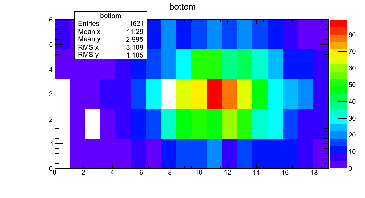
In the position sensitive testing, we got the MIPs counts map both of the top and the bottom layer(see Figure 7). In the plot, the X and Y axis unit is the readout channel. The color shows different counts of the MIPs in each detector. In the figure, we can see that except 5 bad channels in the bottom layer(the white pixels), the gravity of two layers is almost same in X axis. An offset about half of Y unit exists in the Y axis, because of the detector structure(see Figure 2). The spot covers an area about 5*3, which is in accord with the small-sized scintillator.
4 Conclusion
With the cosmic ray test, the matrix can distinguish the MIPs signal from the electronics noise clearly, while the position can be confirmed by the channel sequence. Through a long time running, the matrix is optimized for the DAMPE prototype. The results of the DAMPE prototype test will be presented in near future.
5 Acknowledgements
This work is supported by the Chinese Strategic Priority Research Program in Space Science, CAS. The authors also greatly appreciated the collaboration with the DAMPE colleagues from the University of Science and Technology of China(USTC) and the Purple Mountain Observatory(PMO) during the electronics and the DAMPE prototype test.
References
- [1] M. Aguilar et al., Phys. Rev. Lett. 110, 141102(2013)
- [2] J. Chang, J. H. Adams, H. S. Ahn et al, Nature 456, 362-365 (2008)
- [3] O. Adrianiet al., Nature 458, 607 (2009)
- [4] M. Ackermann et al., Phys. Rev. Lett. 108, 011103(2012)
- [5] VA140 documentation - V0R1
- [6] G. Ambrosi, Nuclear Instruments and Methods in Physics Research A 435 (1999) 215-223