Excitation of fountain and entrainment instabilities at the interface between two viscous fluids using a beam of laser light
Abstract
We report on two instabilities called viscous fountain and viscous entrainment triggered at the interface between two liquids by the action of bulk flows driven by a laser beam. These streaming flows are due to light scattering losses in turbid liquids, and can be directed either toward or forward the interface. We experimentally and numerically investigate these interface instabilities and show that the height and curvature of the interface deformation at the threshold and the jet radius after interface destabilization mainly depend on the waist of the laser beam. Analogies and differences between these two instabilities are characterized.
pacs
43.25.Qp, 42.50.Wk.

When the bottom fluid is pumped through a tube above a horizontal interface separating two immiscible fluids, the upper fluid is withdrawn
and a jet occurs above a threshold flow rate. This phenomenon, called selective withdrawal before the threshold and viscous entrainment after it, has been intensively investigated
in the last decades [1, 2, 3] and find applications in vulcanology [4], encapsulation [5] or emulsification [6].
The opposite configuration, called capillary fountain, where a bottom liquid is pushed through a tube,
into a top fluid (usually air) has also been investigated numerically and experimentally even though focusing on inviscid flows [7, 8].
While the flows at the origin of these interface instabilities and jets were induced mechanically, we show that it is possible to produce contactless similar flows using focused light.
It is well known that a laser beam propagating through two-layer liquid systems can induce interface deformations and hydrodynamic flows of different natures.
While non homogeneous heating in absorbing liquids produces Marangoni and thermo-convection flows [10, 9, 11, 12], radiation pressure effects
occur at the interface separating fluids with different refractive indices [13, 14, 15].
Besides, considering non absorbing turbid liquids, optical streaming flows can be generated by transfer of linear momentum to the liquid in the bulk due to the scattering
of the incident beam [16]. The resulting viscous stress
exerted by the streaming flow can as well deform a soft liquid interface which adopts various shapes depending on the beam power.
When the beam power is low, the viscous stress deforms the interface into a steady wide
hump that have first been reported in Schroll et al. [17] and which properties have been investigated numerically in Chraibi et al. [19].
Above a beam power threshold, the hump destabilizes producing an unsteady cylindrical jet.
While these jets were observed experimentally [17, 20] in the case where the viscous stress due
to optical streaming and radiation pressure act in the same
direction (as in Fig.1 (a1)), making difficult to separate the exact contribution of each effect, we demonstrate here,
experimental jetting instabilities exclusively due to optical streaming (Fig.1 (a2, a3)) where radiation pressure and viscous stress are in opposition. These results are supported by
numerical predictions.
In this letter, we demonstrate that two kind of instabilities called fountain and entrainment respectively, can be produced at the
interface between two liquids by the action of optical streaming flow depending whether this flow is directed toward or forward the interface.
We experimentally and numerically investigate the transition between the steady hump configuration and the unsteady jet in term of optical power and characteristic
lengths at the threshold. Once the jet is formed, we characterize the dependence of its radius to
the beam power and to the capillary length. Analogy with the viscous selective withdrawal [1] is discussed.
The experimental apparatus consists in a continuous Gaussian laser beam at wavelength in vacuum, of power and beam waist , propagating through two liquid systems with different configurations.
Configurations (1) and (2) (Fig.1) were performed in a Winsor III equilibrium of n-Dodecane and brine with a small amount of AOT surfactant [21].
Sodium chloride is used to screen electrostatic repulsion between surfactant heads allowing for a significant reduction of the interfacial tension (up to ). The transparent aqueous phase and
the turbid sponge-like phase at equilibrium are set in contact to form a liquid-liquid system separated by a soft interface. Configuration (3) was performed in a near-critical two-phase microemulsion
(described in Ref. [22]) where we can control the turbidity by varying the difference between the sample temperature and the critical temperature of the system.
Figure shows the three different configurations used in this investigation. The interface can be either pushed (Fig.1 (a1, b1, c1)), pulled (Fig.1 (a2, b2, c2)) or both pushed and pulled (Fig.1 (a3, b3, c3)) by
the viscous stress. At low beam powers (b1, b2, c2), steady wide humps are obtained, while increasing the beam power induces a jetting instability (a1, a2, a3).
Figure 1 (c1, c2, c3) show the variation of the steady hump height as a function of the beam power . When increasing the beam power, we first observe a linear regime (described in Ref. [19])
followed by a sudden increase of the deformation amplitude. The last symbol represented in each figure corresponds to the last stable hump height before the instability threshold.
In order to characterize this instability and to perform quantitative comparisons with numerical results, we solve the hydrodynamic problem using a numerical algorithm based on the Boundary Element Method, detailed in Ref. [19] and summarized hereafter.
The numerical procedure consists in solving the axisymmetric two-phase Stokes equations, in addition to mass conservation :
| (1) |
The gravitational force is included in the corrected pressure term defined as , being the pressure in fluid . is the fluid velocity and the viscosity.
We have introduced the cylindrical coordinate system with orthonormal basis .
is the body force density resulting from light scattering and due to momentum conservation in each liquid (). is the forward momentum
attenuation coefficient ( for a transparent liquid) and the refractive index. is the celerity of light in vacuum and the Gaussian light intensity of the weakly focused laser beam.
As our investigation is dedicated to optical streaming, radiation pressure is not modeled in the numerical simulation, therefore we set .
Indeed, the effects of the optical streaming are not well understood, and the role of the present numerical simulations is to show its influence on the interface without adding the
complexity of secondary effects due to radiation pressure.
The hydrodynamic stress balance on the interface (described by its height ) involving interfacial tension and gravity effects is written as
| (2) |
is
the corrected hydrodynamic stress tensor and is the unit vector normal to
the interface directed from fluid 1 (bottom) to fluid 2 (top).
is the double mean curvature of the axisymmetric
interface in cylindrical coordinates.
Marangoni effects due to the laser heating were neglected as justified in a previous investigation [18].
The motion of the interface follows a Lagrangian approach and we assume continuity of the velocity at the interface with no slip at the boundaries.
We define the capillary length as .
For the sake of simplicity, and in adequation with the experiments, we consider in the numerical resolution and
where and are respectively the thicknesses and the radial extension of the liquid layers. We also
define the capillary number such as [19]. , and respectively correspond to the cases where the interface is pushed, pulled or both pushed and pulled (pp).

Numerical results showing the interface profile for and for the three configurations are reported in figure 2.
Below the instability threshold (Fig. 2 (b)), we notice that the interface adopts a steady hump shape showing small differences between the three configurations.
When the interface is destabilized (Fig. 2 (a)) an unsteady elongated shape emerges. The radius of these nearly cylindrical shapes depends on the chosen configuration. The variations of the deformation amplitude versus are shown
for the three configurations in the inset of Fig. 2 (a). Beyond the linear regime (up to ), depends on the configurations.
This asymmetry is also observed on the evolution of the tip curvature in figure 3.
When the interface is pushed, the increase of the dimensionless tip curvature with
is slower than the increase of the dimensionless hump height and saturates when approaching the threshold value ().
Conversely, when the interface is pulled, or both pushed and pulled (pp), increases much more rapidly than and a logarithmic behavior
is observed . This logarithmic behavior is very similar to the results of viscous selective withdrawal when is large compared to the tube diameter of the pumping [1].
This is probably because in both cases the interface is pulled by the viscous stress exerted by the flow of the top liquid. In the viscous selective withdrawal, it is
sucked through a tube while in our case it is induced by a beam centered bulk force.


A comparison between experimental and numerical results near the instability threshold is provided in figure 4 for the push-pull configuration ;
data from push and pull configurations (figure 1) are too scarce and too scattered near threshold to be presented due
to the high beam power required for interface deformation in Winsor phases.
Numerical results for the push (fountain) and pull (entrainment) configurations are also presented.
For the push-pull case, we first observe, a universal behavior for numerical data for
all beam waists investigated when plotting as a function of where and
are respectively the amplitude of the deformation and the capillary number at the instability threshold.
The inset of figure 4 shows a log-log representation of the previous results. A power law fit was performed on the numerical results ;
The best fit exponents are respectively for the push, pull and pp configurations with an uncertainty of .
In order to understand the transition of the interface shape near the threshold, we investigated the dependence of
its characteristic lengths (threshold height and curvature ) and force balance (represented by ) as a function of
which compares hydrodynamic and optical characteristic length scales.

Figure 5 (a) shows the variation of the dimensionless threshold hump height versus . A qualitative agreement between the experimental and the numerical results is observed. The inset of this figure, indicates that the dimensionless curvature is almost independent of , therefore when the interface is pushed and when the interface is pulled, showing the highest tip curvature in the pull configuration. Figure 5 (b) represents the variation of as a function of . We also notice a very small dependence of versus showing that for the numerical results. This means that the interface is destabilized when the vertical viscous stress becomes larger than , i.e. when . Indeed, below the threshold, the vertical viscous stress is small enough to ensure that on the interface, while at the threshold, the vertical stress becomes so important that no steady solution is achievable (i.e. on the interface), leading to the instability.
Nonetheless, a discrepancy is noticed when comparing the experimental results to the numerical simulations. It is attributed to radiation pressure which is experimentally present and act in the present case in opposition to the viscous stress.
Radiation pressure was not modelled because of non trivial wave guiding effects [15] and in order to focus on optical streaming.
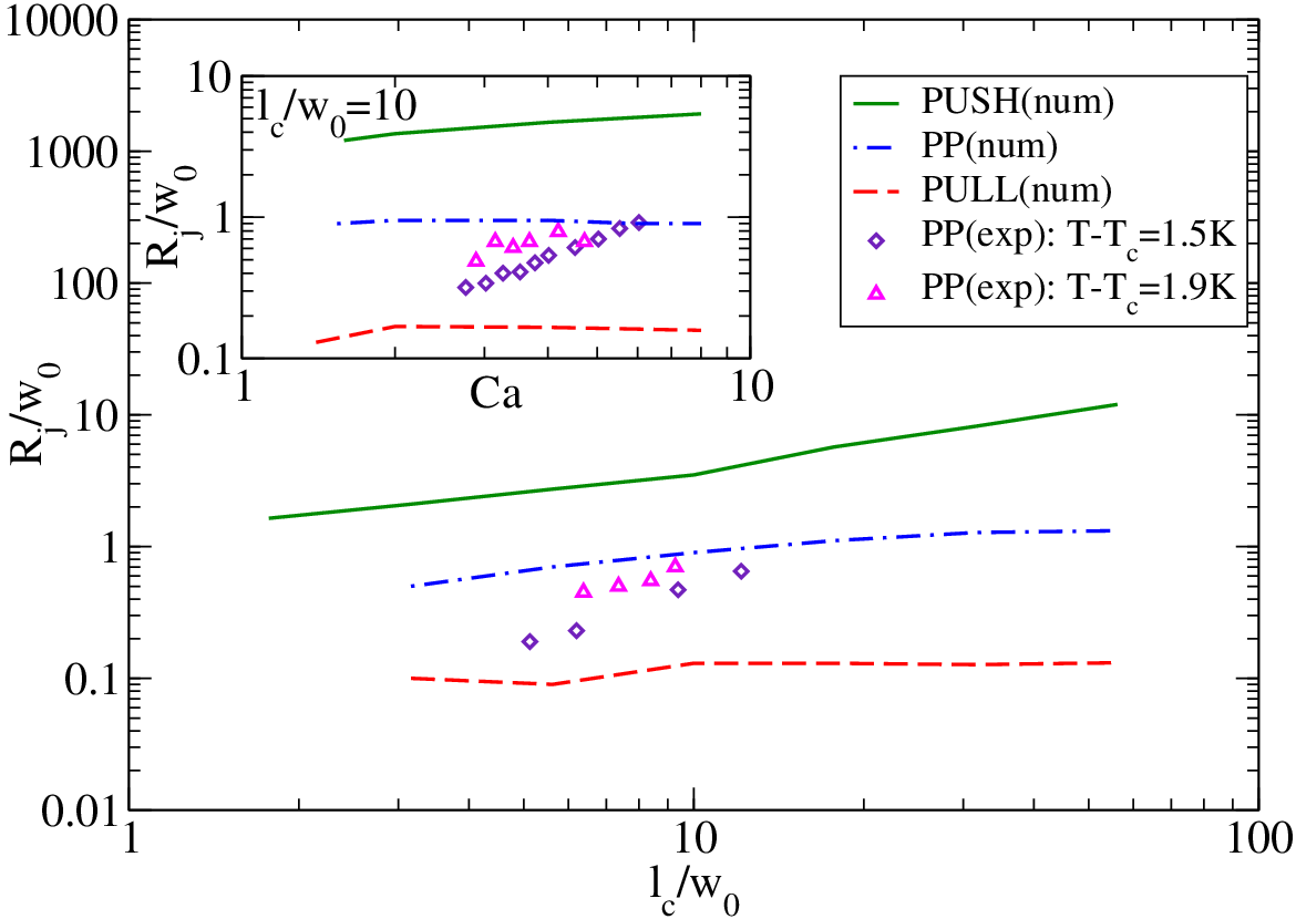
The characteristics of the jet are presented in figure 6. It reports the variation of the dimensionless jet radius as a function of . We can first
notice that the radius of the jet has a very different value depending on whether the interface is pushed () or pulled ().
This demonstrates that the shape of the jet strongly depends on the mechanism that led to its formation. Therefore, as the fluid is injected by the light beam towards the interface, a viscous fountain has a larger radius
than an entrained jet where the fluid is sucked by the beam. Figure 6 also points out a small increase of with , a qualitative agreement between numerical results and experiments can be seen as well.
Finally, the influence of the capillary number on the jet radius is reported in the inset of figure 6, showing a small increase of with .
To conclude, we evidenced two new interface instabilities, optical viscous fountain and entrainment, both based on the transfer of linear momentum from a light beam to turbid viscous liquids due to light scattering. We showed that
depending on the amplitude of the viscous stress generated by the optical streaming, the interface can adopt either a steady bell shape or the form of an unsteady jet. Different configurations were investigated, as the interface can be pushed, pulled or both pushed and pulled by the viscous stress. When the interface
is pulled, our results emphasized a logarithmic coupling between the deformation amplitude and the tip curvature which is very similar to viscous withdrawal behaviors [1].
In addition, we demonstrated that when the characteristic lengths of the problem are well separated (i.e. a container of very large size comparing to the capillary length and to
the beam waist) the tip curvature at the threshold is inversely proportional to the beam waist while the jet radius is nearly proportional to it. Finally, we showed that the tip curvature at the threshold is the smallest and the jet radius the largest
when the interface is pushed compared to the other configurations. Therefore, the mechanisms of withdrawing the fluid (producing viscous entrainment) or pushing it towards the interface (to form a viscous fountain) produce
an interesting asymmetry which reveals important features that could find many concrete applications such as the contactless actuation of microfluidic flows [23].
* Corresponding authors’ e-mails : h.chraibi@loma.u-bordeaux1.fr, jp.delville@loma.u-bordeaux1.fr
References
- [1] M. K. Berkenbusch, I. Cohen & W. W. Zhang, J. Fluid Mech., 613, 171, 2008
- [2] S. C. Case & S. R. Nagel, Phys. Rev. Lett., 98, 114501, 2007
- [3] F. Blanchette & W. W. Zhang, Phys. Rev. Lett., 102, 144501, 2009
- [4] S. Blake & G. N. Ivey, J. Vulc. and Geoth. Res., 27, 153-178, 1986
- [5] I. Cohen, H. Li, J. L. Hougland, M. Mrksich, and S. R. Nagel, Science 292, 265 (2001).
- [6] J. Eggers, Phys. Rev. Lett. 86, 4290 (2001).
- [7] R. M. S. M. Schulkes, J. Fluid. Mech., 261, 223-252 (1994).
- [8] C. Clanet, J. Fluid. Mech., 366, 333-350 (1998).
- [9] M. F. Schatz & G. P. Neitzel., Ann. Rev. of Fluid Mech., 33, 93, 2001.
- [10] J. P. Longtin, K. Hijikata, & K. Ogawa, Int. J. Heat Mass Transfer, 42, 85, 1999.
- [11] I. V. Marchuk, Jour. of Eng. Thermophysics, 18(3), 227, 2009.
- [12] H. Chraïbi & J.-P. Delville, Phys. Fluids , 24, 032102, 2012
- [13] A. Ashkin & J. M. Dziedzic, Phys. Rev. Lett., 30, 139, 1973
- [14] J. Z. Zhang & R. K. Chang, Opt. Lett., 13, 916, 1988
- [15] N. Bertin, H . Chraïbi, R. Wunenburger, J.-P. Delville & E. Brasselet, 109, 244304, 2012
- [16] A. Y. Savchenko, N. V. Tabiryan & B. Y. Zeldovich, Phys. Rev. E, 56, 4773, 1997
- [17] R. D. Schroll, R. Wunenburger, A. Casner, W. W. Zhang & J.-P. Delville, Phys. Rev. Lett., 98, 133601, 2007
- [18] H. Chraïbi, D. Lasseux, E. Arquis, R. Wunenburger & J.-P. Delville, Eur. J. Mech./B Fluids, 27, 419, 2008
- [19] H. Chraïbi, R. Wunenburger, D. Lasseux, J. Petit & J.-P. Delville, J. Fluid Mech., 688, 195, 2011
- [20] R. Wunenburger, B. Issenmann, E. Brasselet, C. Loussert, V. Hourtane & J.-P. Delville, J. Fluid Mech., 666, 273, 2010
- [21] H. Kellay & J. Meunier, J. Phys. Condens. Matter, 8, A49, 1996
- [22] A. Casner & J.-P. Delville, Phys. Rev. Lett., 87, 054503, 2001
- [23] D. Baigl, Lab. Chip, 12 (19) , 3637-3653, 2012