Protected quantum computing:
Interleaving gate operations with dynamical decoupling sequences
Abstract
Implementing precise operations on quantum systems is one of the biggest challenges for building quantum devices in a noisy environment. Dynamical decoupling (DD) attenuates the destructive effect of the environmental noise, but so far it has been used primarily in the context of quantum memories. Here, we present a general scheme for combining DD with quantum logical gate operations and demonstrate its performance on the example of an electron spin qubit of a single nitrogen-vacancy center in diamond. We achieve process fidelities 98% for gate times that are 2 orders of magnitude longer than the unprotected dephasing time .
pacs
03.67, 33.35, 76.70Realizing the potential of quantum computation [1, 2] hinges on the implementation of fault-tolerant systems that complete the computational process with high fidelity even in the presence of unavoidable environmental perturbations. Quantum error correction (QEC) offers this possibility, at the cost of an overhead in the number of qubits, provided that the error per gate can be kept sufficiently low [3] and the preparation of the initial states is achieved with sufficiently high fidelity [4, 5]. Achieving these goals requires additional techniques for eliminating the effect of perturbations both between and inside the quantum operations. Ideally, these additional measures should require little or no additional resources.
Dynamical decoupling (DD) is an attractive approach for protecting the qubit system against unwanted environmental interactions, which may be static or time-dependent. It relies on a sequence of control operations applied to the system, which refocus the system-environment interaction. It does not require additional qubits, and DD sequences can be designed such that they work reliably even in the presence of unavoidable experimental imperfections [6, 7]. Experimental tests of DD have demonstrated this potential by reducing decoherence rates in different systems by several orders of magnitude [8, 9, 10, 11, 12, 13, 14].
While most of these tests demonstrated the protection of single qubits in quantum memories, environmental noise also degrades the fidelity of quantum gate operations during computational processes[15]. If the relaxation mechanism is known it is possible to design protected quantum gates by optimal control techniques [16]. If the system environment is not characterized, it may be still possible to use DD technique for protecting quantum gate operations. In the simplest case, quantum operation can be made robust against static noise by refocusing them in a similar manner to a Hahn echo [17]. In the case of a general fluctuating environment, the Hahn Echo must be replaced by DD methods. Initial experiments demonstrating decoherence protected quantum gates have been made recently on Nitrogen Vacancy (NV) Centers [18] , semiconductor quantum dots [19] and solid state nuclear spins [15].
Possible approaches to build DD protected gates were proposed by several groups [15, 20, 21, 22, 23, 24, 25]. The simplest way to combine DD and gate operations consists of applying the operations between two consecutive DD cycles. It was theoretically shown that this approach can lower the resource requirements for QEC [22]. However, if the duration of a single gate operation is comparable to or longer than the decoherence time of the system, this approach will fail. It becomes then necessary to apply protection schemes in parallel to the gate operation. This must be done in such a way that the DD, which is designed to eliminate the effect of interactions with the environment, does not eliminate the interaction between the qubits and the control fields driving the gate operation.
In this Letter we demonstrate how it is possible to modify general logical gate operations in such a way that they can be interleaved with DD sequences without using auxiliary or encoded qubits. Our method removes the system-environment interaction for any gate operation at least to first order and it allows one to combine arbitrary DD sequences with any type of quantum gate operations.
We consider a system governed by the Hamiltonian
where describes the internal Hamiltonian of the qubit, is a time-dependent control Hamiltonian driving the logical gates, is the interaction of the qubit with the environment, and describes the evolution of the environmental degrees of freedom. Our goal is to implement gate operations protected against environmental noise. Our target operation is a unitary gate that is not affected by the system-environment interaction :
Here, the gate operation is a pure system operator, is the Dyson time ordering operator and is the duration of the gate operation.

Protecting the system from the environmental noise while simultaneously driving logical gate operations can be achieved by using a standard DD sequence and inserting a suitably adapted gate operation in short increments in the free precession periods of the DD sequence. Figure 1 illustrates this for the XY-4 DD sequence: in the free precession periods between the DD pulses, we insert a control Hamiltonian , where indicates the period for which this Hamiltonian is active. The evolution of the system can then be written as
| (1) |
where is the number of pulses of the DD sequence ( in the case of XY-4), is the propagator describing the DD inversion pulse, the cartesian component of the spin operator and is the evolution between two DD pulses. We assume that these periods are short and the control Hamiltonians are time-independent within each period. We treat the DD pulses as ideal rotations.
To find the required control Hamiltonians , we re-write eq. (1) in the form
where the Hamiltonians
describe the control fields in the so-called toggling frame [26] of the DD sequence, which is defined by the transformations
which include the limiting cases (identity). This approach guarantees first order protection to any operation interlaced with a suitable dynamical decoupling sequence.
As a specific example, we choose the XY-4 and XY-8 DD sequences to protect the gate operations NOOP (no operation, i.e, identity), NOT, Hadamard and Phase gate, which can be represented as
To protect these gates, we first split them up into segments that can be interleaved with the DD sequence. A possible decomposition is
with time running from left to right. Here, denotes a pulse with flip angle and phase . The transformation into the toggling frame changes the phases to
The lower part of Fig. 2 shows the resulting sequence, combining the gate operation and the DD cycle, together with the red pulse that generates the initial condition, and the readout pulse (blue).

While we have discussed the example of the XY-4 sequence, the scheme is equally applicable to other DD schemes. In the case of the XY-8 DD sequence, the protected operation has the general form
where the flip angles and phases are listed in Table 1 and and implement the DD pulses.
| NOT | |||||||||
| Hadamard | 0 | 0 | 0 | ||||||
| Phase | |||||||||
| NOT | 0 | 0 | 0 | 0 | 0 | ||||
| Hadamard | 0 | 0 | 0 | ||||||
| Phase | 0 | 0 | 0 | 0 | 0 |
For the experimental test, we used the nitrogen-vacancy (NV) centre of diamond [27], which has an electronic spin . Here we use the subsystem consisting of the and as a single qubit. We apply a magnetic field along the NV symmetry axis to lift the degeneracy of the states. In the secular approximation, we can write an effective Hamiltonian for the two-level system as
Here and denote the electron and nuclear spin operators, and their resonance frequencies, the hyperfine coupling between the electron and the nuclear spin, and the dipolar coupling within the nuclear spin bath that generates the environmental noise.
In the experiment, we optically address a single NV center using a green solid-state laser and a home-built confocal microscope. An acousto-optical modulator with 58 dB extinction ratio and 40 ns rise-time generates the laser pulses from the CW laser and a 4 GS/s arbitrary waveform generator (AWG) synthesizes the microwave (MW) pulses at a carrier frequency of 400 MHz. The output of the AWG is then up-converted by mixing it with the signal from an MW synthesizer operating at 2.4 GHz. The upper sideband is extracted by a suitable band pass filter, which attenuates the lower sideband by 40 dB. The pulses are sent through an 8 W amplifier and a 20 copper wire attached to the diamond surface.
Figure 2 illustrates the pulse sequence for implementing a NOT gate protected by an XY-4 cycle and measuring the performance. The first laser pulse initializes the spin into state . The second laser pulse implements the measurement of the population of state . The MW pulse sequence is applied between the two laser pulses. The first MW pulse initializes the state into the input state required for the process tomography, and the last pulse implements the required readout.
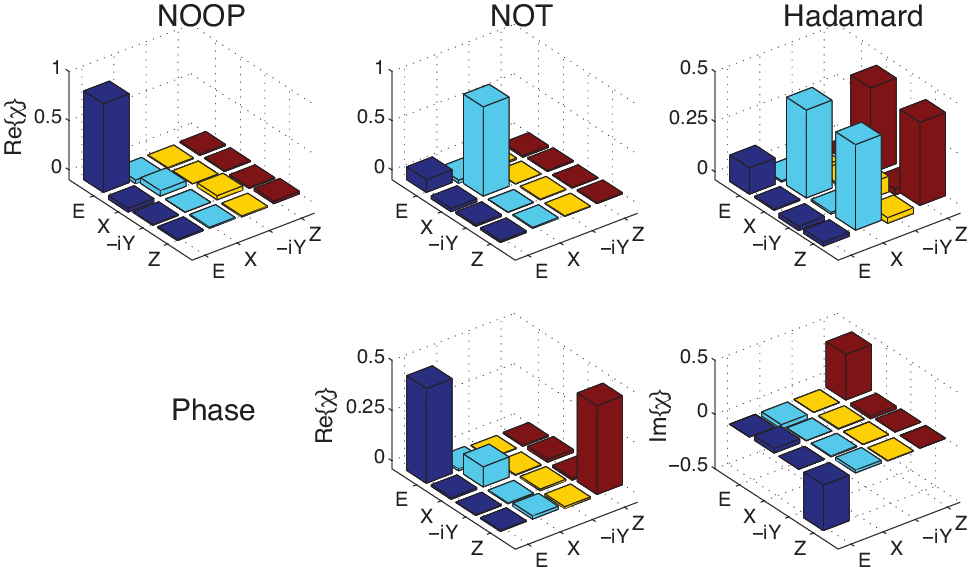
For a quantitative evaluation of the effectiveness of our scheme, we used quantum process tomography [20] to describe the process as , where the basis operators are and , and represent Pauli operators. For each protected gate, we prepared four states , , and as the input states. To analyze the output states, we used quantum state tomography, which requires four readout operations. Here, we used , , and . Figure 3 shows the measured matrices for all four gate operations protected by the XY-8 sequence, each for a gate duration of s. For the first three gates, where the -matrices of the ideal gates are real, we only show the real part. The imaginary parts have rms values of , and , respectively.
These matrices prove that the experimentally implemented gates agree well with the targeted gate operation. We thus conclude that our method of interleaving gate operations with DD sequences works and avoids destructive interference between the gate operation and the DD sequence.

To compare the efficiency of the protection schemes quantitatively, we determined the gate fidelity from the matrices as [28]
| (2) |
where and denote the theoretical and experimental matrices, respectively. For the matrices represented in Fig. 3, the measured gate fidelities are , , , for the protected NOOP, NOT, Hadamard and Phase gates. In figure 4, we show how the gate fidelity changes with increasing gate duration. While the fidelity of the unprotected gates drops sharply on a timescale of , the protected gates retain fidelities of the order of % for up to 80 - clearly demonstrating that the protection against environmental noise works well also for the gate operations.
| Gate | DD cycle | [] | ||
|---|---|---|---|---|
| NOOP | - | 1.01 | 0.19 | 2.6 |
| XY-4 | 0.99 | 38.2 | 17.0 | |
| XY-8 | 0.99 | 71.3 | 18.2 | |
| NOT | - | 0.99 | 0.36 | 2.9 |
| XY-4 | 0.99 | 29.8 | 9.6 | |
| XY-8 | 0.99 | 74.7 | 7.9 | |
| Hadamard | - | 0.99 | 0.36 | 3.9 |
| XY-4 | 0.98 | 32.4 | 6.9 | |
| XY-8 | 0.97 | 77.3 | 6.6 | |
| Phase | - | 0.99 | 0.32 | 3.5 |
| XY-4 | 0.98 | 33.2 | 4.6 | |
| XY-8 | 0.98 | 83.4 | 6.3 |
For a quantitative evaluation, we fit the experimental data with the function [12, 29]. Table 2 lists the parameters obtained from this fit. Within experimental uncertainty, the amplitude of all gates is very close to 1.0. The most important parameter for assessing the effectiveness of the scheme is the decay time of the gate fidelity. Compared to the unprotected gates, the gates protected by XY-4 extend this lifetime by factors of , , and , for NOOP, NOT, Hadamard and Phase gates, respectively, and the XY-8 scheme achieves factors of , , and .
The decay of the gate fidelity in the NV center is dominated by the hyperfine interaction with the 13C nuclear spins, which are present at 1.1 % of the sites in diamond (natural abundance). In addition, the electron spin is also coupled to the 14N nuclear spin (I=1) of the NV center, through a hyperfine interaction of . In contrast to the nuclear spin bath, this single spin represents a time-independent perturbation, which also affects the gate performance, and the coupling strength is significantly larger than that of the 13C nuclear spins. In the data shown in Fig. 4, we eliminated its effect by an appropriate choice of the delays between the pulses. In Fig. 5, we explicitly show its effect for the example of the Hadamard gate. The data shown here correspond to an expanded scale of the data also represented in the lower left panel of Fig. 4, but with higher resolution and using a linear scale. The oscillations visible in the experimental as well as the simulated data are due to the hyperfine interaction between the electronic and the 14N nuclear spins. The damping of the experimental oscillations, which is not visible in the simulated data, can be attributed to the interaction with the 13C nuclear spin bath, which was not considered in the simulations. Clearly, the protection scheme is also helpful for this type of interaction. In the inset of the figure, we show how this effect can be eliminated by increasing the Rabi frequency of the control pulses.

In conclusion, we have introduced a scheme for protecting quantum logical gate operations against environmental noise by segmenting the gate operations and interleaving it with a pulse cycle for dynamical decoupling. The interleaving process requires that the segments of the gate operations are modified in such a way that the DD pulses effectively transform them into the operations required by the algorithm. In the experimental example, using the NV center of diamond, we demonstrated that protected gates retain high fidelity for durations that are more than two orders of magnitude longer than for unprotected gates. In future work, we plan to extend this work to other DD sequences and to multiqubit systems.
We gratefully acknowledge experimental assistance from J.H. Shim and useful discussions with G.A. lvarez. This work was supported by the DFG through grant Su 192/27-1.
References
- [1] M. A. Nielsen and I. L. Chuang, Quantum Computation and Quantum Information (Cambridge University Press, Cambridge, England, 2000).
- [2] J. Stolze and D. Suter, Quantum Computing: A Short Course from Theory to Experiment (Wiley-VCH, Berlin, 2008), 2nd ed.
- [3] E. Knill, R. Laflamme and W. H. Zurek, Science, 279, 342 (1998).
- [4] S. Bravyi and A. Kitaev, Phys. Rev. A 71, 022316 (2005).
- [5] A. M. Souza, J. Zhang, C. A. Ryan, and R. Laflamme, Nat. Comm. 2 , 169 (2010).
- [6] A. M. Souza, G. A. lvarez, and D. Suter, Phil. Trans. R. Soc. A 370, 4748 (2012).
- [7] M. A. Ali Ahmed, G. A. lvarez, and D. Suter, Phys. Rev. A 87, 042309 (2013).
- [8] M. J. Biercuk, H. Uys, A. P. VanDevender, N. Shiga, W. M. Itano, and J. J. Bollinger, Nature 458, 996 (2009).
- [9] J. Du, X. Rong, N. Zhao, Y. Wang, J. Yang, and R. B. Liu, Nature 421, 1265 (2009).
- [10] G. A. lvarez, A. Ajoy, X. Peng, and D. Suter, Phys. Rev. A 82, 042306 (2010).
- [11] G. deLange, Z. H. Wang, D. Risté, V. V. Dobrovitski, and R. Hanson, Science 330, 60 (2010).
- [12] C. A. Ryan, J. S. Hodges, and D. G. Cory, Phys. Rev. Lett. 105, 200402 (2010).
- [13] A. M. Souza, G. A. lvarez, and D. Suter, Phys. Rev. Lett. 106, 240501 (2011).
- [14] A. Ajoy, G. A. lvarez, and D. Suter, Phys. Rev. A 83, 032303 (2011).
- [15] A. M. Souza, G. A. lvarez, and D. Suter, Phys. Rev. A 86, 050301 (2012).
- [16] T. Schulte-Herbruggen, A. Sporl, N. Khaneja, and S. J. Glaser, J. Phys. B: At. Mol. Opt. Phys. 44, 154013 (2011).
- [17] M. D. Shulman, O. E. Dial, S. P. Harvey, H. Bluhm, V. Umansky, and A. Yacoby, Science 336, 202 (2012).
- [18] T. van der Sar, Z. H.Wang, M. S. Blok, H. Bernien, T. H. Taminiau, D. M. Toyli, D. A. Lidar, D. D. Awschalom, R. Hanson, and V. V. Dobrovitski, Nature 484, 82 (2012).
- [19] C. Barthel, J. Medford, C. M. Marcus, M. P. Hanson, and A. C. Gossard, Phys. Rev. Lett. 105, 266808 (2010).
- [20] K. Khodjasteh and L. Viola, Phys. Rev. Lett. 102, 080501 (2009).
- [21] K. Khodjasteh, D. A. Lidar, and L. Viola, Phys. Rev. Lett. 104, 090501 (2010).
- [22] J. R. West, D. A. Lidar, B. H. Fong, and M. F. Gyure, Phys. Rev. Lett. 105, 230503 (2010).
- [23] K. Khodjasteh and L. Viola, Phys. Rev. A 80, 032314 (2009).
- [24] H.-K. Ng, D. A. Lidar, and J. Preskill, Phys. Rev. A 84, 012305 (2011).
- [25] P. Cappellaro, L. Jiang, J. S. Hodges, and M. D. Lukin, Phys. Rev. Lett. 102, 210502 (2009).
- [26] U. Haeberlen, in Advances in magnetic resonance, edited by J. Waugh (Acad. Press, New York, 1976), Advances in magnetic resonance, Supplement 1.
- [27] J. Wrachtrup and F. Jelezko, J. Phys.: Condens. Matter 18, S807 (2006).
- [28] X. Wang, C.-S. Yu, and X. Yi, Phys, Lett. A 373, 58 (2008).
- [29] J. Shim, I. Niemeyer, J. Zhang, and D. Suter, Eur. Phys. Lett. 99, 40004 (2012).