Optimized Parallel Transmission in Elastic Optical Networks to Support High-Speed Ethernet
Abstract
The need for optical parallelization is driven by the imminent optical capacity crunch, where the spectral efficiency required in the coming decades will be beyond the Shannon limit. To this end, the emerging high-speed Ethernet services at 100 Gbps, have already standardized options to utilize parallel optics to parallelize interfaces referred to as Multi-lane Distribution (MLD). OFDM-based optical network is a promising transmission option towards the goal of Ethernet parallelization. It can allocate optical resource tailored for a variety of bandwidth requirements and that in a fundamentally parallel fashion with each sub-carrier utilizing a frequency slot at a lower rate than if serial transmission was used. In this paper, we propose a novel parallel transmission framework designed for elastic (OFDM-based) optical networks to support high-speed Ethernet services, in-line with IEEE and ITU-T standards. We formulate an ILP optimization model based on integer linear programming, with consideration of various constraints, including spectrum fragmentation, differential delay and guard-band constraints. We also propose a heuristic algorithm which can be applied when the optimization model becomes intractable. The numerical results show the effectiveness and high suitability of elastic optical networks to support parallel transmission in high-speed Ethernet. To the best of our knowledge, this is the first attempt to investigate the parallel transmission in elastic optical networks to support standardized high-speed Ethernet.
I Introduction
The need for optical parallelization is driven by the imminent optical capacity crunch [1], which has gained significant attention after studies have shown that capacity upgrades of conventional single-mode fiber systems have slowed down from about per year to about per year since 2002 [1][2]. Given the massive growth of Internet data, it became clear that optical communications had to shift towards spectral efficiency, i.e., transmitting more information over the fundamentally limited bandwidth of optical amplifiers. It has become apparent that without parallelization, the spectral efficiency of about 20b/s/Hz required in the coming decades, will be beyond the Shannon limit [2]. As a consequence, the high-speed Ethernet has resorted to a parallel solution as standardized in IEEE802.3ba, especially for 40/100 Gigabit Ethernet (40/100GE) and beyond, to overcome the Shannon limit without an expense on reduced transmission distance. Instead of using high-speed serial interfaces, 40GE and 100GE utilize parallel optics to split traffic across multiple lanes with lower rates, which is referred to as Multi-lane Distribution (MLD) [3]. To this end, it has been specified that 40 Gbps Ethernet (40GE) and 100 Gbps Ethernet (100GE) can utilize 4 lanes and 10 lanes, respectively, with each lane running at 10.3125 Gbps [3]. To this end, ITU-T has extended the Optical Transport Network (OTN) information structure especially for 40GE and 100GE traffic. As it is, the concept of parallel transmission for high speed Ethernet presents a myriad of new challenges in the optical layer.
We believe that recently proposed elastic optical networks based on Orthogonal Frequency Division Multiplexing (OFDM) technology carry the promise of a potentially transformative parallel transmission solution in the optical layer, due to its fundamental parallel nature. With OFDM, optical spectrum is actually sliced or parallelized into a sequence of frequency slots and signals are modulated on frequency slots in form of sub-carriers. Since the sub-carriers are orthogonal in the frequency domain, signals modulated on them can be received in parallel without interference. Hence, the OFDM-based elastic optical networks can efficiently support parallel transmission of high-speed Ethernet by modulating traffic on a group of parallel sub-carriers, with each sub-carrier at a lower data rate. High-speed Ethernet can thus take full advantage of Optical Virtual Concatenation (OVC) protocol in OTNs for parallel transmission over spectrum bands in OFDM networks, where a spectrum band is composed of a group of consecutive sub-carriers. With OVC protocol, Ethernet lanes are carried by sub-carriers in multiple spectrum bands as though they were virtually contiguous. At the same time, parallel transmission can easily alleviate the fundamental trade-off between bit rate and the optical reach, as it is known that all-optical transmission distance falls as the serial bit rate increases. This is due to the imperfections in the optical fibers, such as transmission loss, non-linear effects, group velocity dispersion (GVD), polarization mode dispersion (PMD), etc.

We present an illustrative example in Fig.1, where spectrum on each fiber is sliced or, as we also refer it to as parallelized into 10 sub-carriers (dashed lines are the subcarriers already ”allocated”). OTN layer acts as an adaptation layer mapping the Ethernet traffic onto optical frames (ODUs). Here, 100Gbps Ethernet (100GE) signal is firstly distributed into 10 lanes in a round-robin fashion in the Ethernet layer, each lane carrying a 10Gbps Ethernet signal. After that, each lane is mapped onto Optical channel Data Unit (ODU) of appropriate size, i.e., ODU2e, which are then mapped into Optical channel Transport Unit (OTU2e) at speed of approximately 11.09Gbps. In the optical layer, data carried on each OTU2e channel is modulated to optical signal and transmitted on sub-carriers in the elastic optical network. The number of sub-carriers depends on the high-speed Ethernet transmission rate and capacity per sub-carrier. Assume each sub-carrier can support one OTU2e channel, 10 sub-carriers are required in this example. We define a group of concecutive sub-carriers as a Spectrum Band (SB). A connection may be set up using multiple spectrum bands, depending on the spectrum availability. For instance, three spectrum bands are used in Fig.1, i.e., SB1, SB2 and SB3.
In this paper, we investigate the suitability of OFDM-based networks to support parallel transmission in high speed Ethernet, and address the imminent challenges in its implementation. First, we address the issue spectrum fragmentation [4][5]. Most of Routing and Spectrum Assignment (RSA) methods focu on allocating sub-carriers required by a connection in a consecutive spectrum range, which can not take full advantage of parallel nature of elastic optical networks. We show that optimization methods can be used to minimize the spectrum fragmentation. Second, we show that also the differential delay issue can be effectively addressed, as it normally occurs when traffic is distributed into sub-carriers across diverse fibers. Specifically, we not only optimize the differential delay, but we also show that it can be bounded according to the requirements in the current standards and commercial products11 1 ITU-T G.709 [6] suggests that the realignment process has to be able to compensate a differential delay of at least 125. In terms of commercial products, it has been reported that a commercial framer device can support differential delay using internal memory and up to using off-chip Synchronous Dynamic Random Access Memory (SDRAM)[7][8].. We formulate a novel optimization model based on Integer Linear Programming (ILP) to find an optimal set of sub-carriers which are used in the parallel transmission, while minimizing overall usage of optical spectrum. In addition, we propose a heuristic algorithm which can be applied in the scenarios where the optimization model becomes infeasible. The numerical results show the effectiveness and high suitability of elastic optical networks to support parallel transmission in high-speed Ethernet. To the best of our knowledge, this is the first attempt to investigate the parallel transmission in elastic optical networks to support standardized high- speed Ethernet.
The rest of the paper is organized as follows. Section II present a background overview, including the differential delay issue, spectrum fragmentation and key technologies as well as the implications of the assumptions we make. In Section III, we present the ILP model and a heuristic algorithm. We show the numerical results in Section IV. Section V provides a literature review. We conclude the paper in Section VI.
II Background
II-A Key Technologies
The feasibility of parallel transmission problem studied in this paper stems from the inherent parallelism in the high-speed Ethernet and elastic OFDM-based optical layers, as specified in the current standards. Traditionally, Gigabit Ethernet transmission relies on duplex fiber cabling with one fiber deployed for each direction. The high-speed Ethernet standard, i.e., IEEE 802.3ba, specified Multiple Lane Distribution (MLD) to split high-speed serial Ethernet data into multiple virtual lanes in a round-robin fashion, as it was shown earlier in Fig.1. As a result, the parallel optics systems are used in every Ethernet cabling solution. For instance, the 40Gbps Ethernet calls for a solution of 12-fiber cabling, with each channel featuring four dedicated fibers for transmitting and receiving respectively, while saving the remaining four fibers as dark fibers for reliability [3] .
In the optical layer, the built-in inverse multiplexing protocol in OTN, i.e., optical virtual concatenation (OVC), has been proposed to enable parallel transmission in optical networks precisely. As standardized in ITU-T G.709, OTN defines a set of optical wrappers with different size [9]. The client traffic is mapped into an optical wrapper of appropriate size and transmitted at corresponding line rates, referred to as OTU. The OTN information structure supports line rates varying from approximately 2.5Gbps () to 112 Gbps (). Of note is that the OTN information structure has been recently updated in order to support the new emerging high-speed Ethernet services, in particular for 40Gbps and 100Gbps Ethernet. Two new optical wrappers are defined, referred to as, OTU3e2 (44.58Gbps) and OTU4 (112Gbps) respectively [6]. The technological maturity of OTN layer, including synchronization, error correction, framing and differential delay compensation, can be utilized to facilitate the parallel transmission in elastic optical networks to support high-speed Ethernet. Moreover, elastic optical networks with OFDM technologies enables the mapping between the optical wrappers and sub-carriers enabling parallel transmission without complicated data processing.
II-B Differential Delay in Parallel Transmission in OFDM-based Optical Networks
In general, parallel transmission in OFDM-based networks falls under two categories: (i) single spectrum band transmission, (ii) multiple spectrum bands transmission. In the first scenario, the required number of sub-carriers can be allocated within a single spectrum band from source to destination. In the second scenario, multiple spectrum bands are allocated to support the high-speed Ethernet transmission. The multiple spectrum bands can be transmitted over the same or diverse fibers from source to destination. In either category, each sub-carrier generally experiences different end-to-end delay, i.e., even when transmitted over the same fibers and within the same spectrum band. For instance, in Fig.1, the sub-carriers in spectrum bands and can experience the delay difference resulting from the imperfections in optical fibers, even if transmitted over the same optical path or different paths with the same length. Thus, we distinguish between two main types of differential delay in parallel transmission in OFDM-based networks: (i) fiber effects caused differential delay, and (ii) path diversity caused differential delay.
II-B1 Fiber effects caused differential delay
The main fiber effect to cause differential delay is the Group Velocity Dispersion (GVD), which is caused by the fact that sub-carriers on different frequencies travel (in form of waves) at different speeds. The longer wave travels faster than the shorter waves, resulting in different propagation delay even in the same spectrum band. According to the principle of GVD, the maximum delay difference caused by GVD in a spectrum band can be approximated as:
| (1) |
where is the fiber dispersion at the central frequency; and are the highest frequency and smallest frequency of the spectrum band, see [10]; and is the transmission distance. The condition of Eq.(1) is that the central frequency is much larger than . The OFDM-based optical networks follow the same spectrum dimension as it is in “fix grid” [11], i.e., the central frequency is = 193.1 THz, which is much larger than the frequency difference value in any spectrum band. Hence, the approximation presented in Eq.(1) can be directly applied. As an example, we assume that 100GE utilizes a spectrum band composed of 10 consecutive sub-carriers for parallel transmission and also assume that each frequency slot is 50GHz22 2 A frequency slot is generally smaller than 50GHz. Here, we assume the standardized channel spacing, i.e., 50GHz as an example. , i.e., channel spacing is 0.4nm. The fiber dispersion of a Single Mode Fiber (SMF) is 17 ps/nm/km at the the central frequency [10]. Hence, the maximum differential delay caused by dispersion in the parallel transmission is 0.68 for a connection with physical distance of .
II-B2 Path diversity caused differential delay
Another, and more commonly considered, type of differential delay in parallel transmission is caused by the path diversity. When spectrum bands used in the parallel transmission traverse different fiber-level paths, the different transmission distance along different paths also lead to the differential delay. The differential delay caused by the path diversity can be simply calculated as , where is the signal propagation speed in the path and is the path length. Considering the standard SMF where the signal propagation speed is , for a connection with length of , the maximum differential delay between spectrum bands would be .
II-C Spectrum Fragmentation

As previously mentioned, the nature of connection demands from high-speed Ethernet, which can be fine and coarse grained, may exacerbate the so-called spectrum fragmentation. To better understand this problem, we show an example in Fig.2, where optical spectrum on each fiber link is assumed to be sliced into 16 frequency slots, with one sub-carrier on each frequency slot. The traffic demand is defined as , where , and denote source, destination, and the number of required sub-carriers, respectively. In this example, 2 sub-carriers are assigned as the guard-band (typically used to insulate the adjacent spectrum bands). As it can be seen in Fig.2, the spectrum on all fiber links are fragmented after the allocation of 6 spectrum bands, i.e., . Upon the arrival of , the request is rejected if it is only allowed to set up a single spectrum path with four consecutive sub-carriers. In fact, under current network condition, any traffic demand requesting more than 3 sub-carriers will be blocked, even though there are sufficient sub-carriers available in the network. This phenomena is particularly pronounced in case of high-speed Ethernet services with a transmission rate of 40/100 Gbps which require a large number of consecutive sub-carriers. However, this issue can be effectively resolved by distributing Ethernet traffic into non-consecutive parallel spectrum paths. In the example shown in Fig.2, can be accommodated by allocating two spectrum bands, i.e., and , with two sub-carriers per band.
II-D Assumptions and Discussion
In this paper we assume all sub-carriers have the same transmission rate. In OFDM-based optical networks, however, it has been shown that the capacity per sub-carrier can be adaptively managed by using different modulation formats for different transmission distances [12][13]. For instance, in our Fig.1, spectrum band 1 (SB1) would use a transmitter at higher transmission speed with a higher level modulation format. In this paper, however, we stay with the assumption that all sub-carriers have the same transmission rate for practical implementation. This assumption simplifies the mapping between OTN frames and sub-carriers, thus facilitating the actual implementation of optical parallel transmission in practice.
The analysis of differential delay issue shown earlier has indicated that the main factor of differential delay in parallel transmission is path diversity. Considering the same transmission distance, the maximum differential delay caused by the GVD among sub-carriers is insignificant comparing with the delay difference caused by propagation, e.g., vs. . Therefore, our results for heuristic evaluation will only consider the differential delay caused by path diversity. However, the optimization model proposed in the next section can account for the issue of differential delay among sub-carriers, which maybe useful for new materials inducing new fiber propagation properties. Finally, we assume that the differential delay is compensated in the OTN layer in the our architecture.
III Parallel Transmission Algorithms
In this section, we first present the preliminaries and provide definitions of basic concepts used. After that, we present the optimization model based on Integer Linear Programming (ILP) and a heuristic algorithm which can find single or multiple spectrum paths for parallel transmission upon the arrival of a connection request from high-speed Ethernet.
III-A Preliminaries
For an easy understanding of the proposed algorithms, we first summarize the notations in Table I and clarify the terminologies as follows:
- •
Sub-carrier: Alike wavelength in WDM networks, a sub-carrier is a channel which carries signals in OFDM based elastic optical networks. Sub-carriers are orthogonal to each other; spacing between their central frequencies is , where is a frequency slot. [14]
- •
Guard-band (GB): We define a guard band is the spectrum necessary to insulate two spectrum bands.
- •
Spectrum path: A spectrum path is composed of a spectrum band continuous from source to destination, i.e., it is composed of a group of consecutive sub-carriers with same index from the source to the destination node.
- •
Fiber-level path: A fiber-level path is a route from source to destination, including all the fiber links in between, over which one or multiple spectrum bands can be allocated in either non-consecutive fashion.
The terms that are specially defined for parallel transmission scenarios are given as follows:
Definition 1.
Spectrum band (SB): We define the Spectrum Band as a group of spectrally consecutive sub-carriers allocated to the same spectrum path. A spectrum path can not take two spectrum bands on the same link.
Definition 2.
Maximum acceptable differential delay: The maximum differential delay between two spectrum paths used in the parallel transmission. It depends on the electronic layers, e.g., OTN layer in our case, where the electronic buffer is available. It is denoted as in this paper.
| Symbol | Description |
|---|---|
| A graph represents an elastic optical network with nodes in set and edges in set | |
| A sub-carrier with index | |
| The size of a frequency slot | |
| An ordered set contains all frequency slots (sub-carriers) on a link, | |
| A set contains available frequency slots on link | |
| Delay of the link , integer value | |
| Length of link | |
| A connection demand, where , and are source, destination, the required number of sub-carriers, respectively | |
| GB | One or multiple sub-carriers assigned to insulate two adjacent spectrum paths |
| Maximum acceptable differential delay | |
| A spectrum path composed of a group of consecutive sub-carriers | |
| A fiber-level path which is a sequence of fiber links between source and destination | |
| A path set that contains all the spectrum paths computed for the connection | |
| A path set that contains all the fiber-level paths computed for connection | |
| Maximum number of fiber-level paths can be used, |
| Symbol | Description |
|---|---|
| Binary variable; it equals to 1 if a spectrum path is used by the connection demand, otherwise it is 0 | |
| Binary variable; it equals to 1 if a spectrum path uses , otherwise it equals to 0 | |
| Binary variable; it equals to 1 if a spectrum path uses sub-carrier , otherwise it equals 0 | |
| Binary variable; it is 1 if a spectrum path uses sub-carrier on link , otherwise it is 0 | |
| Binary variable; it equals to 1 if spectrum paths and share at least one link, otherwise it is 0 | |
| Integer variable; it denotes delay of spectrum path | |
| Integer variable; it denotes the number of sub-carriers allocated to the spectrum path | |
| Integer variable; it denotes the differential delay caused by GVD on the spectrum path |
III-B ILP Optimization Model
We define the objective of the ILP model as minimizing the usage of sub-carriers for a spectrum allocation request, i.e.,
| (2) |
The proposed ILP model relies on the variables summarized in Table II and subject to the constraints defined as follows:
Routing constraints:
Eq.(3) ensures that traffic on the routed path can be added and dropped only at source and destination nodes, respectively. Constraint defined in Eq.(4) guarantees that a spectrum path starts from the source node and ends at the destination node. Finally, Eq.(5) eliminates the loops at source and destination nodes.
| (3) |
| (4) | ||||
| (5) |
Spectrum continuity constraint: In this paper, we restrict that all spectrum paths to be all-optical between source and destination nodes [15], i.e., restricted by spectrum continuity constraint. Eq.(7) indicates that sub-carrier with index is assigned to the spectrum path from the source node. Eq.(8) specifies that a spectrum path can only use sub-carriers with same index on all fiber links it traverses.
| (7) |
| (8) |
Spectrum consecutive constraints: For efficient modulation, consecutive sub-carriers are required in a spectrum band when it is assigned to a spectrum path [11]. The spectrum consecutive constraints are defined in Eq.9 and Eq.10. Eq.(9) determines the number of sub-carriers allocated to path .
When two sub-carriers with index and are used for , the right-hand side of Eq.(10) equals to . This constraint ensures that the gap between two sub-carriers should be equal to or less than .
When and are not used at the same time, the right-hand side of Eq.(10) results in an infinite value, which keeps Eq.(10) true.
| (9) |
| (10) |
Non-overlapping constraints: To avoid collision, a sub-carrier can not be assigned to multiple spectrum paths at the same time. The binary variable is defined to denote if two spectrum paths and have at least one common link. The value of is determined by Eq.(11) and Eq.(12). When path and share at least one fiber link, equals to 1, otherwise, equals to 0. Eq.(13) specifies that a spectrum slot can not be assigned to and at the same time if two paths have common links, i.e., either or can be equal to 1 when . Finally, Eq.(14) defines that spectrum assignment only happens when a path is used by the connection demand.
| (11) | ||||
| (12) | ||||
| (13) | ||||
| (14) |
The constraint defined in Eq.(12) is non-linear. We define a new binary variable denoted as , hence Eq.(12) is linearized as follows:
| (15) | ||||
| (16) | ||||
| (17) | ||||
| (18) |
Guard-band constraint:
The constraint defined in Eq.(19) specifies that the spectrum assignment only happens when the available sub-carriers are sufficient to meet the guard-band requirement. When a sub-carrier is allocated to a path , a sub-carrier within the range cannot be allocated to other paths, i.e., all sub-carriers within the range are excluded from the available spectrum set of link for other paths.
Eq.(20) ensures that a guard-band exists between two spectrum paths and , if they share at least one common link. When and have no
common link, equals to 0, which guarantees that Eq.(20) is always true.
| (19) |
| (20) |
Bandwidth constraint: This constraint ensures that the number of sub-carriers assigned to all the spectrum paths for connection demand is equal to the traffic demand ,
| (21) |
Differential delay constraint: Differential delay in OFDM-based networks are mainly caused by the fiber effects and path diversity, as it is discussed in Sec.II B. We denote the maximum differential delay caused by the GVD on path as . is calculated based on the Eq.(1). As shown in Eq.(22), is the gap between the highest frequency and the lowest frequency of a spectrum band. calculates the length of the path .
| (22) |
Note that Eq.(22) is non-linear. We hence define an integer variable, denoted as , . The GVD constraint can be linearized as shown in Eq.(23).
| (23) |
The variable is restricted by the constraints defined in Eq.(24) Eq. (25) and Eq.(26), which determine that the value of is either zero or equal to . The delay of a path is defined in Eq.(27). Hence the total differential delay is defined in Eq.(28), which can not exceed the buffering capacity of the electronic layers. i.e., the differential delay between any two spectrum paths used for a connection can not exceed (Eq.(28)).
| (24) |
| (25) |
| (26) |
| (27) |
| (28) |
Discussion:
III-B1 Problem Size
The complexity of an ILP formulation is known to be exponential, i.e. , where is the number of variables. Thus the proposed ILP model for multiple path computation and spectrum assignment for parallel transmission has an exponential complexity with in , where is the number of used paths, and are number of links and number of sub-carriers respectively. It makes the optimization model computationally expensive and rather infeasible in practice. Take a simple example, for a network of size , , there are node pairs. For each node pair, there are instances of . Assume four paths are used in the connection, i.e., , we have 13440 variables. Other variables can be calculated in a similar way. Thus, the total number of variables in the ILP model is very high even for small networks.
III-B2 Complexity Reduction
The problem size can be reduced by pruning the variables. A common method used in the literature is to compute a set of paths in advance and use them as input to the ILP model. However, the solutions are limited in the pre-computed path set in this case and the complexity of the advance path computation should also be considered.
III-C Heuristic Algorithm
In this section, we propose a heuristic algorithm which decomposes the parallel transmission problem into two sub-problems, i.e., multipath computation and spectrum assignment, as shown in Alg.1. The objective and constraints of ILP model are also considered in the heuristic algorithm. In addition, we limit the maximum number of fiber-level paths in order to reduce the complexity, i.e., maximum fiber-level paths are computed for a given traffic demand.
III-C1 Multipath Computation
The first phase of the proposed heuristic algorithm is to compute a set of fiber-level paths which are used as input to the spectrum assignment (phase 2 in Alg.1). The algorithm starts from collecting all paths originating from source node . All outgoing links from are placed in a set denoted as and sorted in an increasing order of path delay. The shortest path in , denoted as , is selected and extended to all the nodes connected to the sink node of , i.e., . Afterwards, the path set is updated with the extended links and the shortest path from current is selected. The same procedure is repeated till the shortest path in reaches the destination node . The computed path is placed in fiber-level path set and removed from . The algorithm continues to select the shortest path from the updated and repeats the path computation. It breaks when no path can be computed or fiber-level paths have been computed. In the worst case scenario, the phase 1 of Alg.1 has to visit all the nodes in the network to find a path between and . Assume the maximum node degree in the network is , the complexity of multipath computation phase of Alg.1 is in .
III-C2 Spectrum Assignment
In phase 2 of Alg.1, the computed path set, i.e., , is used as input. The algorithm tries to find a single path solution first. It identifies the spectrum path with maximum number of consecutive sub-carriers on each fiber-level path and compares the available bandwidth with . When it fails to find a single path solution, the algorithm continues to find a multipath solution, i.e., aggregating spectrum fragments from multiple spectrum paths. All spectrum paths in are sorted in the increasing order of delay and put in the set . Afterwards, the differential delay and bandwidth constraints are checked. If the differential delay between a spectrum path and the shortest path is no larger than , i.e., , is included in the solution. Note that the GVD caused differential delay is not considered here. The algorithm outputs a solution when bandwidth requirement is satisfied. In the worst case scenario, the phase 2 of Alg.1 has to check all the sub-carriers over all fiber links. Hence, the computational complexity of spectrum assignment phase is in .
IV Performance Evaluation
In this section, we evaluate the performance of the proposed parallel transmission algorithms, under the dynamic traffic conditions. The connection requests arrive following a Poisson process with an average arrival rate of and the holding time of each connection request follows the negative exponential distribution with an average value of time units; thus the traffic load in the network is quantified as in . In our study, the mean inter-arrival time of the connection requests is time unit and mean holding time is varying to achieve different network loads. The measure of blocking probability, as a common metric for assessing the performance, is defined as the percentage of blocked connection requests versus total connection requests. The source and destination pair is randomly selected in the network under study. Fig.3 shows the network topology used in this paper [16].
The ILP model is implemented in Gurobi Optimizer [17] and the heuristic algorithm is implemented with a Java event-driven simulator. We consider two representative values as the maximum acceptable differential delay, i.e., as suggested in ITU-T G.709 [6] and which can be supported by commercial framer mappers[8]. The main results shown in this section are evaluated on the US backbone topology as shown in Fig.3 and have a confidence interval of 95. We study the impact of different number of sub-carriers per fiber () and the maximum number of fiber-level paths () as well as maximum acceptable differential delay () on the proposed algorithms.

IV-A ILP Model Evaluation
Given the complexity issue of ILP optimization, we first evaluate the proposed ILP model in a scaled-down network scenario where an optimal solution can be obtained within a reasonable time. The number of sub-carriers per fiber link is 16; the maximum differential delay is and guard band is set to be one sub-carrier. The heuristic algorithm is also evaluated in the same experimental setting and compared with the ILP model. Afterwards, we study only the heuristic algorithm in a scenario where the ILP model becomes intractable and thus of little practical relevance. The traffic load is generated by the connection requests following Poisson process with bandwidth requirement uniformly distributed between 1 and 4 sub-carriers. When the network is stable at a certain network load, a connection demand requesting between 4 and 6 sub-carriers is sent to a randomly selected source and destination pair and an algorithm is invoked. The same experiment is repeated over 50 times to obtain a mean value.
Table III shows the percentage of blocked connections at each given network load. To study the impact of pre-computed path set, the maximum number of fiber-level paths that can be used in the parallel transmission in the heuristic is set to be 10 and 40, respectively. There is no limitation of number of fiber-level paths used in the ILP evaluation, it stops when the model either finds a solution, or it is time out. It can be seen that ILP model always outperforms the heuristic algorithm when the problem is tractable. For instance, none of the connection requests is blocked using ILP model when network load is . However, and connections are blocked using the heuristic algorithm with =10 and = 40, respectively. When the network load increases, the number of blocked connections increases with both the ILP model and the heuristic. However, the performance of proposed heuristic algorithm is getting close to the ILP model when the pre-computed paths are sufficient. For instance, mutipath routing with a set of 40 precomputed fiber-level paths leads to around blocking at while the ILP model leads to blocking at the same network load.
This set of results shows that the main disadvantage of the proposed heuristic is the issue of pre-computed paths set. However, the heuristics can always find a solution in a reasonable time, which may be single or multiple spectrum paths. At the same time, we have observed that the ILP becomes infeasible when high network load or with more sub-carriers per fiber link in the network.
| Load | Heuristic | Heuristic | ILP |
| () | (= 10) | (= 40) | |
| 30 | 16.0132% | 8.0723% | 0.000% |
| 35 | 24.823% | 10.419% | 6.025% |
| 40 | 34.392% | 18.362% | 14.025% |
| 45 | 40.015% | 22.753% | 20.902% |
IV-B Performance of the Heuristic Algorithm
In this section, we investigate the performance of proposed heuristic algorithm. The simulation parameters are summarized in Table IV. Connection requests are uniformly distributed on the randomly selected source and destination nodes. Average 20,000 connection requests are generated at every network load; and every experiment is repeated 5 times to obtain an average value. We distinguish two parallel transmission scenarios which are defined as follows:
Definition 3.
Parallel transmission on single spectrum path (ST): The required sub-carriers are allocated on the shortest spectrum path. Differential delay issue is hence not considered.
Definition 4.
Parallel transmission on multiple spectrum paths (PT): Here, the required sub-carriers are not restricted to a single spectrum path. In general, multiple spectrum bands from a single fiber, or from multiple fiber links can be used. In the results shown in this section, the heuristic algorithm with maximum allowable differential delay and are denoted as PT-1 and PT-2, respectively.
| F: number of frequency slots per link | 128 |
|---|---|
| GB: number of sub-carries as guard-band | 0-3 |
| : number of requested sub-carriers | 5,10,15 |
| : maximum number of fiber-level paths | 30 |
| PT-1: with large buffer | |
| PT-2: in line with ITU-T G.709 |
IV-B1 Blocking Probability vs. spectrum requirements and network loads
Fig.4 shows the blocking probability of parallel transmission with different spectrum requirements. Here, we assume there is no guard-band between adjacent spectrum paths, i.e., . It can be seen that allowing for multiple spectrum paths in the parallel transmission can increase the acceptance ratio of connection requests, leading to the reduction of blocking probability. With the increase of the spectrum requirement, the blocking probability also increases. For instance, the connection requests are blocked with restricted to a single spectrum path (ST) at traffic load of . With , maximum connection requests with SP at traffic load of . Regardless of the spectrum requirements and network loads, parallel transmission over multiple spectrum paths, i.e., PT-1 and PT-2, can always lead to a lower blocking probability, due to the fact that spectrum fragments are now aggregated instead of “wasted” in case of ST. When network load is very high, the performance of PT is also getting worse, especially when connection granularities are large. It will eventually result in the same performance as ST, as shown in Figs. 4(b) and 4(c).
IV-B2 Impact of Differential Delay Constraint
The compensation of differential delay in the upper layers can significantly affect the performance of parallel transmission in the underlying optical network. We define PT-1 and PT-2 with maximum acceptable differential delay as and , respectively. As it is discussed in Sec.II-A, for a connection with length of km, the maximum differential delay in a standard single mode fiber is only . Hence, the differential delay constraint of PT-1 is sufficient to cross the longest path in the studied network. It leads to the fact that PT-1 can utilize longer paths comparing with PT-2, thus leading to the lower blocking probability, as shown in Fig.4. With the same experimental settings, e.g., and , blocking probability of PT-1 is less comparing with PT-2. However, since PT-1 consumes more spectrum resources by using longer paths, and it will fail to find a solution for a request requiring large number of sub-carriers when network load is high. As shown in Fig.4(c), the blocking probability of PT-1 is higher than PT-2 at network load of .
IV-B3 Impact of Guard-band
When the guard-band is required, parallel transmission with multiple spectrum paths may consume more resources on guard-bands, counteracting its benefits. Fig.5 shows the performance of parallel transmission with single and multiple spectrum paths in terms of blocking probability. It can be seen that both PT-1 and PT-2 can still reduce blocking probability, comparing with single spectrum path only (ST). However, with increasing network load, the resource consumed by guard-bands required by multiple spectrum paths leads to the degradation of performance, despite the PT aggregating spectrum fragments. As shown in Fig.5(a) and Fig.5(b), PT-1 has the best performance when network load is low. When the network load is high, e.g., and with and , respectively, both PT-1 and PT-2 have almost the same blocking probability as the ST.
When spectrum requirements are high, e.g., , it is not easy to find spectrum paths for both ST and PT. While PT-1 tends to reserve more resources by allowing for long paths, it has the highest blocking probability with , as shown in Fig.5(c). However, PT-2 has very strict differential delay constraint, i.e., , it leads to the similar performance as SP with the increasing network load. It is due to the fact that PT-2 can only find a single spectrum path as the solution under this network condition.
IV-B4 Spectrum Fragments Aggregation Ratio
As it has been discussed before, the proposed parallel transmission algorithm tries to aggregate spectrum fragments when it can not find a single spectrum path. Hence, the fraction of connections that are served with multiple spectrum paths implies how often the spectrum fragments are aggregated.
Definition 5.
Spectrum fragments aggregation ratio is defined as the percentage of connection requests served with multiple spectrum paths when parallel transmission algorithms are applied. It is affected by the bandwidth requirements and differential delay constraints.
Fig. 6 presents measurements under three different loads (Erlang load * spectrum requirement ()). As it can be seen from Fig.6, the restrict differential delay constraint in PT-2 () results in less connections using multiple spectrum paths. At low and medium loads ( and 550, respectively), most requests ( 95 %) are served with a single spectrum path and in the case of PT-2, the remaining requests are served mostly ( 98 %) using only 2 spectrum paths. In case of medium load () with a large spectrum requirement(), PT-1 aggregates spectrum fragments more frequently comparing with PT-2. Around connection requests are served with 2 spectrum paths and connections are using 3 spectrum paths. connections are set up with 4 spectrum paths and the others use higher number of spectrum paths. In case of PT-1, maximum 10 spectrum paths were used for connection requests.

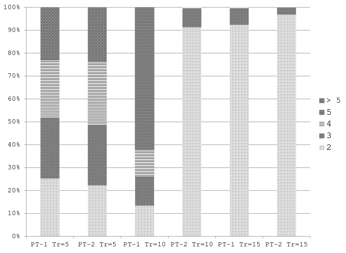
This behavior is even more pronounced at high network loads: the distribution of the requests served by multiple spectrum paths vs. the number of spectrum paths used is presented in Fig. 7. As it can be seen in Fig.7, PT-2 uses only 2 spectrum paths for most connection requests, while a small fraction of connections using 3 spectrum paths. However in the case of PT-1, as the requirement for spectrum slots increases, the fraction of connections using more spectrum paths also increases, with some connections also recorded using as many as 15 spectrum paths, each with a single spectrum slot. The unbounded nature of the number and length of the spectrum paths in PT-1 imply that algorithm can provision spectrum slots across disproportionately longer paths as compared to the single path algorithm (ST). As a result, it leads to blocking of future connection requests, thereby degrading the performance of the algorithm at high network loads.
IV-B5 Impact of Network Topologies
Finally, we evaluate the parallel transmission in a different network as shown in Fig.8. Fig.9 and Fig.10 show the blocking probability of connection requests requesting large number of sub-carriers (). It can be seen that parallel transmission over multiple spectrum paths can reduce blocking probability in general in a small network. While the small network limits the maximum path length in PT-1, the large differential delay constraint leads to the better performance in terms of the blocking probability. As shown in Fig.9, PT-1 can still reduce around blocking probability comparing with ST at high network loads (e.g., ), while PT-2 has almost the same performance as ST due to the strict differential delay constraint.

V Related Work
Since 2010, IEEE 802.3ba has standardized parallel transmission as the solution for high-speed Ethernet with ever increasing transmission rate which can be beyond 100Gbps in the near future [3]. In particular, 100GE has specified 10 parallel lanes, leveraging the mature 10Gbps technology in optical networks. To enable parallel transmission over Wide Area Network (WAN), the International Telecommunication Union-Telecommunication Standardization Sector (ITU-T), has augmented their G.709 OTN information structure for high-speed Ethernet at transmission of 40Gbps and 100Gbps [6].
It is no coincidence that about the same time, the optical network have started to approach the so-called optical capacity crunch [1], where the capacities of single-mode fiber were shown to be reaching the Shannon limit in a few years from now [18][2]. Optical parallel transmission was coined in [18] as the most promising solution for the optical capacity crunch. Optical spatial multiplexing and so-called photonic MIMO (Multiple Input Multiple Output) were proposed to explore the optical parallelism, which can multiplex multiple fiber strands or multiplexing multiple modes in a fiber [2].
In addition, optical networks are also shifting to improving spectral efficiency. It is known that conventional WDM networks have limit on the spectral efficiency. Therefore, it was easy for us to recognize that the inherent parallelism makes OFDM based optical networks a valid candidate for the high-speed Ethernet parallel transmission. Only by looking at early work SLICE proposed in [11], where optical spectrum is sliced into frequency slots, it can be seen that traffic is distributed to the parallel sub-carriers, each utilizes one frequency slot (in parallel). However, up to now, none of the existing work has addressed the issues of high-speed Ethernet parallel transmission in the context of elastic optical networks.
In [4], we presented a study of optimal algorithms for finding multiple parallel paths in elastic optical networks applicable to problems shown in this paper. Also, optical parallel transmission in support of high-speed Ethernet was investigated in our past paper [19] for the first time, where an optimized parallel transmission framework based on OTN/WDM networks was proposed. In parallel to our work, proposals have been presented also in [20] and [21]. In [20], the authors proposed a heuristic algorithm for dynamic multipath provisioning in OFDM based elastic optical networks. In [21], a hybrid single path and multipath routing scheme was proposed for flexible online service provisioning in elastic optical networks. The authors proposed two heuristic algorithms, with consideration of path computation on the fly and usage of pre-computed paths.
The present paper is different from the previous body of work, since it is an optimization framework for dynamic computations of parallel transmission paths in elastic optical networks, with consideration of differential delay bounds within the spectrum bands and also among the spectrum band. Thus, the model is complete from the point of view of parallelization. Moreover, this paper is entirely focused on optical parallel transmission to support high-speed Ethernet. This present paper, thus, for the first time, investigates the effectiveness and feasibility of using parallel OFDM-basedoptical networks to support high-speed Ethernet according to the current IEEE and ITU-T standards, widely accepted by the industry.
VI Conclusion
Parallel transmission has been standardized in IEEE 802.3ba as the solution for high-speed Ethernet with every increasing transmission rates, which poses new requirements to the optical layer, which on its own, is reaching the Shannon limits on capacity. OFDM-based optical networks carry potential to support high-speed Ethernet due to its inherent parallelism. In this paper, we investigated the technical feasibility of parallel transmission in OFDM based networks to support high-speed Ethernet and designed a novel framework which is in-line with current IEEE and ITU-T standards. We formulated an optimization model based on Integer Linear Programming (ILP) for dynamic computation of multiple parallel paths and spectrum assignment, with consideration of differential delay issue caused by path diversity and fiber effects. We also proposed an effective heuristic algorithm which can be applied for scenarios where the optimization model becomes intractable. The numerical results showed that differential delay issue of using multiple parallel paths is not an obstacle and parallel transmission in elastic optical networks is feasible. The parallel transmission framework proposed here can be used to effectively support high-speed Ethernet, while leveraging the maturity of low-speed optical technologies.
References
- [1] A. Chralyvy, “Plenary paper: The coming capacity crunch,” in 35th European Conference on Optical Communication, 2009. ECOC ’09.
- [2] P. Winzer, “Optical networking beyond wdm,” IEEE Photonics Journal, vol. 4, no. 2, pp. 647–651, 2012.
- [3] Carrier Sense Multiple Access with Collision Detection (CSMA/CD) Access method and Physical Layer Specifications, IEEE Std. 802.3ba, 2010.
- [4] X. Chen, A. Jukan, and A. Gumaste, “Multipath de-fragmentation: Achieving better spectral efficiency in elastic optical path networks,” in Mini Conference IEEE INFOCOM 2013, April 2013.
- [5] X. Chen, Y. Zhong, and A. Jukan, “Multipath routing in elastic optical networks with distance-adaptive modulation formats,” in IEEE ICC 2013, June 2013.
- [6] “Interfaces for the optical transport network (OTN),” ITU-T Recommendations. [Online]. Available: http://www.itu.int/rec/T-REC-G.709/e
- [7] “Cisco sl-series.” [Online]. Available: http://www.cisco.com/-en/US/products/hw/modules/ps2710/ps5479/index.html
- [8] “Intel ixf19301 datasheet.” [Online]. Available: http://www.intel.com/design/network/products/optical/tsp/IXF19301.htm
- [9] A. Gumaste and N. Krishnaswamy, “Proliferation of the optical transport network: A use case based study,” IEEE Communications Magazine, vol. 48, no. 9, pp. 54–61, Sept. 2010.
- [10] Y. Sun, T. Ono, A. Takada, and M. Tomizawa, “Wavelength-group-based optical virtual concatenation technique for data-intensive and latency-sensitive applications,” in IEEE International Conference on Communications Workshops, 2008, pp. 179–183.
- [11] M. Jinno, H. Takara, B. Kozicki, Y. Tsukishima, Y. Sone, and S. Matsuoka, “Spectrum-efficient and scalable elastic optical path network: architecture, benefits, and enabling technologies,” IEEE Communications Magazine, vol. 47, Nov. 2009.
- [12] K. Christodoulopoulos, I. Tomkos, and E. Varvarigos, “Elastic bandwidth allocation in flexible ofdm-based optical networks,” IEEE/OSA Journal of Lightwave Technology, vol. 29, no. 9, pp. 1354–1366, May 2011.
- [13] M. Jinno, B. Kozicki, H. Takara, A. Watanabe, Y. Sone, T. Tanaka, and A. Hirano, “Distance-adaptive spectrum resource allocation in spectrum-sliced elastic optical path network,” IEEE Communications Magazine, vol. 48, no. 8, pp. 138 –145, Aug. 2010.
- [14] W. and J. Djordjevic, OFDM for Optical Communications. Academic Press, Elsevier, 2010.
- [15] Y. Wang, X. Cao, and Y. Pan, “A study of the routing and spectrum allocation in spectrum-sliced elastic optical path networks,” in Proc.IEEE INFOCOM,, Apr. 2011, pp. 1503–1511.
- [16] “Sndlib.” [Online]. Available: http://sndlib.zib.de/home.action
- [17] “Gurobi optimizer.” [Online]. Available: http://www.gurobi.com/
- [18] P. J. Winzer, “Beyond 100g ethernet,” IEEE Communication Magazine, vol. 48, no. 7, pp. 26–30, Jul. 2010. [Online]. Available: http://dx.doi.org/10.1109/MCOM.2010.5496875
- [19] X. Chen and A. Jukan, “Optimized parallel transmission in otn/wdm networks to support high-speed ethernet with multiple lane distribution,” Optical Communications and Networking, IEEE/OSA Journal of, vol. 4, no. 3, pp. 248 –258, march 2012.
- [20] W. Lu, X. Zhou, L. Gong, M. Zhang, and Z. Zhu, “Dynamic multi-path service provisioning under differential delay constraint in elastic optical networks,” IEEE Communications Letters, vol. 17, no. 1, pp. 158 –161, Jan. 2013.
- [21] Z. Zhu, W. Lu, L. Zhang, and N. Ansari, “Dynamic service provisioning in elastic optical networks with hybrid single-/multi-path routing,” Journal of Lightwave Technology, vol. 31, no. 1, pp. 15 –22, Jan 2013.