CORE: Augmenting Regenerating-Coding-Based Recovery for Single and Concurrent Failures in Distributed Storage Systems
Abstract
Data availability is critical in distributed storage systems, especially when node failures are prevalent in real life. A key requirement is to minimize the amount of data transferred among nodes when recovering the lost or unavailable data of failed nodes. This paper explores recovery solutions based on regenerating codes, which are shown to provide fault-tolerant storage and minimum recovery bandwidth. Existing optimal regenerating codes are designed for single node failures. We build a system called CORE, which augments existing optimal regenerating codes to support a general number of failures including single and concurrent failures. We theoretically show that CORE achieves the minimum possible recovery bandwidth for most cases. We implement CORE and evaluate our prototype atop a Hadoop HDFS cluster testbed with up to 20 storage nodes. We demonstrate that our CORE prototype conforms to our theoretical findings and achieves recovery bandwidth saving when compared to the conventional recovery approach based on erasure codes.
Notes: A 6-page shorter conference version of this paper appeared in Proceedings of the 29th IEEE Conference on Massive Data Storage (MSST), May 2013 [29].
1 Introduction
To provide high storage capacity, large-scale distributed storage systems have been widely deployed in enterprises, such as Google File System [14], Amazon Dynamo [9], and Microsoft Azure [4]. In such systems, data is striped across multiple nodes (or servers) that offer local storage space. Nodes are interconnected over a networked environment, in the form of either clustered or wide-area settings.
Ensuring data availability in distributed storage systems is critical, given that node failures are prevalent [14]. Data availability can be achieved via erasure codes (e.g., Reed-Solomon codes [35]), which encode original data and stripe encoded data across multiple nodes. Erasure codes are defined by parameters (where ), such that if any subset of out of nodes fails, the original data remains accessible by decoding the encoded data stored in other surviving nodes. Erasure codes can tolerate multiple failures, while incurring less storage overhead than replication.
In addition to tolerating failures, another crucial availability requirement is to recover any lost or unavailable data of failed nodes. Recovery is performed in two scenarios: (i) when the failed nodes are crashed and the permanently lost data need to be restored on new nodes, and (ii) when the unavailable data needs to be accessed by clients before the failures are restored. The conventional recovery approach, which applies to any erasure codes, first reconstructs all original data to obtain the lost/unavailable data. Since the lost/unavailable data usually accounts for only a fraction of original data, previous studies explore how to optimize the recovery performance by minimizing the amount of data involved. One class of approaches is to minimize I/Os (i.e., the amount of data read from disks) based on erasure codes (e.g., [23, 27, 36, 43, 44]). Another class of approaches is to minimize the recovery bandwidth (i.e., the amount of data transfer over a network during recovery) based on regenerating codes [10], in which each surviving node encodes its stored data and sends encoded data for recovery. In the scenario where network capacity is limited, minimizing the recovery bandwidth can improve the overall recovery performance. In this work, we focus on exploring the feasibility of deploying regenerating codes in practical distributed storage systems.
However, most existing recovery approaches, including those for minimizing I/Os and bandwidth, are restricted to single failure recovery. Although single failures are common, node failures are often correlated and co-occurring in practice, as reported in both clustered storage (e.g., [13, 37]) and wide-area storage (e.g., [5, 18, 30]). To provide tolerance against concurrent (multiple) failures, data is usually protected with a high degree of redundancy. For example, Cleversafe [6], a commercial wide-area storage system, use (16,10) erasure codes (i.e., up to 6 out of 16 concurrent failures are tolerable) [32]. Some wide-area storage systems such as OceanStore [28] and CFS [7] employ erasure codes with even higher double redundancy . We believe that in addition to providing fault tolerance, minimizing the recovery bandwidth for concurrent failures will provide additional benefits for today’s large-scale distributed storage systems. In addition, concurrent failure recovery is beneficial to delaying immediate recovery [2]. That is, we can perform recovery only when the number of failures exceeds a tolerable limit. This avoids unnecessary recovery should a failure be transient and the data be available shortly (e.g., after rebooting a failed node). Given the importance of concurrent failure recovery, we thus pose the following questions: (1) Can we achieve bandwidth saving, based on regenerating codes, in recovering a general number of failures including single and concurrent failures? (2) If we can enable regenerating codes to recover concurrent failures, can we seamlessly integrate the solution into a practical distributed storage system?
In this paper, we propose a system called CORE, which supports both single and concurrent failure recovery and aims to minimize the bandwidth of recovering a general number of failures. CORE augments existing optimal regenerating codes (e.g., [33, 42]), which are designed for single failure recovery, to also support concurrent failure recovery. A key feature of CORE is that it retains existing optimal regenerating code constructions and the underlying regenerating-coded data. That is, instead of proposing new code constructions, CORE adds a new recovery scheme atop existing regenerating codes. Our idea is to treat all but one failed nodes as logical surviving nodes. CORE first reconstructs the “virtual” data to be generated by those logical surviving nodes. By combining the virtual data with the real data being generated by the real surviving nodes, CORE then reconstructs the remaining failed node using existing optimal regenerating codes. We apply the same idea for all failed nodes.
In summary, the contributions of this paper are three-fold.
- •
Theoretical analysis. We theoretically show that CORE achieves the minimum bandwidth for a majority of concurrent failure patterns. We also propose extensions to CORE to achieve sub-optimal bandwidth saving even for the remaining concurrent failure patterns. Our analytical study validates that CORE can recover concurrent failure patterns with significant bandwidth saving over conventional recovery based on erasure codes. For example, for (20,10), the bandwidth savings are 36-64% and 25-49% in the optimal and sub-optimal cases, respectively. We also show via reliability analysis that CORE has significantly longer mean-time-to-failure (MTTF) than conventional recovery.
- •
Implementation. We implement a prototype of CORE and demonstrate the feasibility of deploying CORE in a practical distributed storage system. As a proof of concept, we choose the Hadoop Distributed File System (HDFS) [41] as a starting point. CORE sits as a layer atop HDFS and supports recovery for a general number of failures. We build CORE atop HDFS by modifying the source code of HDFS and its erasure coding extension HDFS-RAID [20]. We also adopt a pipelined implementation that parallelizes and speeds up the recovery process.
- •
Experiments. We experiment CORE on an HDFS testbed with up to 20 storage nodes. Our experiments take into account a combination of different factors including network bandwidth, disk I/Os, encoding/decoding overhead. We justify that minimizing bandwidth in recovery plays a key role in improving the overall recovery performance. We show that compared to erasure codes, CORE achieves recovery throughput gains with up to for single failures and up to for concurrent failures. Our experimental results conform to our theoretical findings. We also evaluate the runtime performance of MapReduce jobs under node failures. We show that CORE can reduce the runtime of a MapReduce job in both single and concurrent failures when compared to erasure codes. Furthermore, our prototype maintains the performance of striping replicas into encoded data, an operation that is included in original HDFS-RAID, when regenerating codes are used.
The rest of the paper proceeds as follows. Section 2 first formulates our system model. Section 3 motivates how CORE reduces bandwidth of conventional recovery. Section 4 describes the design of CORE and presents our theoretical and analysis findings. Section 5 describes the implementation details of CORE. Section 6 presents experimental results. Section 7 reviews related work. Section 8 discusses several open issues of CORE, and finally, Section 9 concludes this paper.
2 System Model
We formulate the recovery problem in a distributed storage system. We also provide an overview of regenerating codes, and show how they can improve the recovery performance.
2.1 Basics
We first define the terminologies and notation. Table 1 summarizes the major notation used in this paper. We consider a distributed storage system composed of a collection of nodes, each of which refers to a physical storage device. The storage system contains nodes labeled by , in which nodes (called data nodes) store the original (uncoded) data and the remaining nodes (called parity nodes) store parity (coded) data. The coding structure is systematic, meaning that the original data is kept in storage.
Figure 1 shows an example of a distributed storage system, which is also consistent with the erasure-coded design of HDFS-RAID [20]. Each node stores a number of blocks. A block is the basic unit of read/write operations in a storage system. It is called a data block if it holds original data, or a parity block if it holds parity data. To store data/parity information, each block is partitioned into fixed-size strips, each of which contains symbols. A symbol is the basic unit of encoding/decoding operations. A stripe is a collection of strips on data nodes and the corresponding encoded strips on parity nodes. A data (parity) block contains all strips of data (parity) symbols. For load balancing reasons the identities of the data/parity nodes are rotated so that the data and parity blocks are evenly distributed across nodes [27, 32].
| number of nodes | |
|---|---|
| the -th node () | |
| number of data nodes | |
| number of symbols per strip | |
| number of concurrent failures () | |
| size of original data stored in a stripe | |
| the -th stored symbol in a stripe of node (, ) | |
| encoded symbol from surviving node used to recover lost data of failed node () |
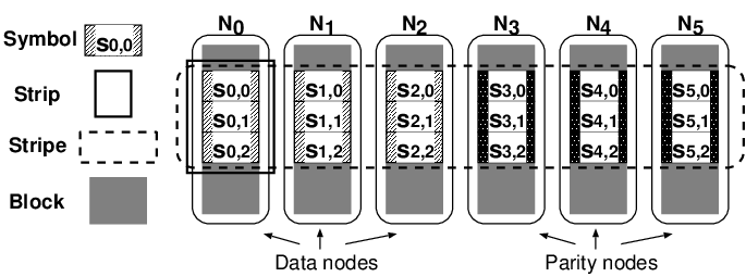
Each stripe is independently encoded. Our discussion thus focuses on a single stripe and our recovery scheme will operate on a per-stripe basis. Let be the total amount of original uncoded data stored in a stripe. Let be a stored symbol of node at offset in a stripe, where and . Each stripe contains stored symbols, which can be formed by multiplying an generator matrix by a vector of original data symbols based on the Galois field arithmetic, whose implementation details can be found in the prior study [16]. In this work, we focus on the arithmetic operations over the Galois field GF(). Note that our recovery scheme applies to the failures of both data and parity nodes. It treats each stored symbol the same way regardless of whether it is a data or parity symbol.
For data availability, we have the storage system employ an code that is maximum distance separable (MDS), meaning that the stored data of any out of the nodes can be used to reconstruct the original data. That is, an MDS-coded storage system can tolerate any out of concurrent failures. MDS codes also ensure optimal storage efficiency, such that each node stores units of data per stripe. Reed-Solomon (RS) codes [35] are a classical example of MDS codes. RS codes can be implemented with strip size to minimize the generator matrix size.
2.2 Recovery
Our recovery addresses two types of node failures. The first type is the recovery from permanent failures (e.g., due to crashes) where data is permanently lost. In this case, we reconstruct the lost data of the failed nodes on new nodes to minimize the window of vulnerability. Another type is degraded reads to the temporarily unavailable data during transient failures (e.g., due to system reboots or upgrades) or before the permanent failures are restored. The reads are degraded as the unavailable data needs to be reconstructed from the available data of other surviving nodes. In our discussion, we use “lost data” to refer to both permanently lost data and temporarily unavailable data.
We consider the scenario where the storage system activates recovery of lost data when there are a number of failed nodes. Clearly, we require , or the original data will be unrecoverable. We call the set of failed nodes the failure pattern. The lost data will be reconstructed by the data stored in other surviving nodes.
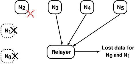
Our recovery builds on the relayer model, in which a relayer daemon coordinates the recovery operation. Figure 2 depicts the relayer model. During recovery, each surviving node performs two steps: (i) I/O: it reads its stored data, and (ii) encode (for regenerating codes only): it combines the stored data into some linear combinations. The relayer daemon performs three steps: (i) download: it downloads the data from some other surviving nodes, (ii) reconstruction: it reconstructs the lost data, and (iii) upload: it uploads the reconstructed data to the new nodes (for recovery from permanent failures) or to the client who requests the data (for degraded reads). We assume that the relayer is reliable during the recovery process.
We argue that the relayer model can be easily fit into practical distributed storage systems. In the case of recovering permanent failures, we can deploy the relayer daemon in different ways, such as in one of the new storage nodes that reconstructs all lost data, in every storage node that reconstructs a subset of lost data, or in separate servers that run outside the storage system. In the case of degraded reads, we can deploy the relayer daemon in each storage client. We note that this relayer model is also used in prior studies in the contexts of peer-to-peer storage [2], data center storage [23], and proxy-based cloud storage [21]. In Section 5, we elaborate how the relayer model can be integrated into a distributed storage system.

To improve the recovery performance of a distributed storage system with limited network bandwidth, it is important to minimize the amount of data transferred over the network. If the number of failed nodes is small, the amount of data being downloaded from the surviving nodes is larger than the amount of reconstructed data being uploaded to new nodes (or clients). If we pipeline the download and upload steps (see Section 5.2), then the download step becomes the bottleneck. Thus, we focus on optimizing the download step in recovery. Formally, we define the recovery bandwidth as the total amount of data being downloaded per stripe from the surviving nodes to the relayer during recovery. Our goal is to minimize the recovery bandwidth.
2.3 Regenerating Codes
When an erasure-coded system sees failures, conventional recovery is used, meaning that the relayer downloads data from any surviving nodes to first reconstruct all original data and then return the lost data. The amount of data being downloaded is equal to the amount of original data being stored (i.e., per stripe). Note that some proposals allow less data to be read for some erasure codes under specific conditions (see Section 7). However, conventional recovery applies to any MDS erasure code and any number of failures no more than . In this paper, when we refer to erasure codes, we assume that conventional recovery is used.
We consider a special class of codes called regenerating codes [10] that enables the relayer to transfer less than the amount of original data being stored. Regenerating codes build on network coding [1], in which during recovery, surviving nodes send encoded symbols that are computed by the linear combinations of their stored symbols, and then the encoded symbols are used to reconstruct the lost data. It is shown that regenerating codes lie on an optimal tradeoff curve between storage cost and recovery bandwidth [10]. There are two extreme points: minimum storage regenerating (MSR) codes, in which each node stores the minimum amount of data on the tradeoff curve, and minimum bandwidth regenerating (MBR) codes, in which the bandwidth is minimized. Note that MSR codes have the same optimal storage efficiency as MDS erasure codes such as RS codes, while MBR codes minimizes bandwidth at the expense of higher storage overhead. In this work, we focus on MSR codes.
Existing optimal MSR codes are designed for recovering a single failure, as described below. First, the strip size has symbols to achieve the minimum possible bandwidth. During recovery, the relayer downloads one encoded symbol from each of the surviving nodes11 1 There are MSR code constructions (e.g., [42, 33]) that can download encoded symbols from less than surviving nodes at the expense of higher recovery bandwidth. In this work, we only focus on the case where surviving nodes are connected.. Let be the encoded symbol downloaded from node and used to reconstruct data for the failed node . Each encoded symbol is a function of the symbols stored in the surviving node , and has the same size as each stored symbol. Using the encoded symbols, the relayer reconstructs the lost symbols of the failed node . MSR codes achieve the minimum recovery bandwidth (denoted by ) for single failure recovery given by [10]:
| (1) |
However, existing studies on regenerating codes are limited in different aspects, which we further discuss in Section 7. To summarize, most recovery approaches focus on single failures. If more than one node fails, the optimal MSR code constructions cannot achieve the saving shown in Equation (1) by connecting to surviving nodes. To recover concurrent failures, a straightforward approach is to resort to conventional recovery and download the size of original data from any surviving nodes. This paper explores if we can achieve recovery bandwidth saving for concurrent failures as well.
3 Motivating Example
Before we describe the design of CORE, we first motivate via an example how CORE reduces the recovery bandwidth over conventional recovery for concurrent failures. The design details of CORE will be refined in Section 4.
We consider an MDS code with and . Suppose that we store a data object of size that corresponds to a stripe of original data symbols. For erasure codes, the strip size is symbol, and the symbol size is . For regenerating codes, the strip size is set to symbols, and hence the symbol size is . Suppose now both nodes and fail. Our goal is to reconstruct their lost data.
We first consider conventional recovery based on erasure codes, whose idea is to first reconstruct all original data. Thus, the relayer downloads the size of original data from any nodes (e.g., ). Figure 3(a) shows the conventional recovery, in which the relayer reconstructs all three original symbols to regenerate the data for the two failed nodes simultaneously. Thus, the total amount of data downloaded is .
We now discuss how CORE applies concurrent failure recovery. Here, we consider the baseline approach of CORE (see Section 4.1). Figure 3(b) shows the main idea, in which the relayer now downloads two encoded symbols and from each of the four surviving nodes (), such that CORE form a system of equations in ’s and ’s to reconstruct the lost data of nodes and . The total amount of data downloaded is , which is one symbol size less than that of conventional recovery. We point out that the bandwidth saving of CORE can be even higher for some parameters. In general, when the baseline approach of CORE applies concurrent failure recovery for failures, the relayer downloads encoded symbols from each of the surviving nodes. We elaborate the details in the next section.
 |
 |
|---|---|
| (a) Conventional recovery (based on erasure codes) | (b) CORE (see Section 4) |
4 Design of CORE
CORE builds on existing MSR code constructions that are designed for single failure recovery with parameters . CORE has two major design goals. First, CORE preserves existing code constructions and stored data. That is, we still have data striped and stored with existing MSR code constructions, while CORE sits as a layer atop existing MSR code constructions and enables efficient recovery for both single and concurrent failures. The optimal storage efficiency of MSR codes is still preserved. Second, CORE aims to minimize recovery bandwidth for a variable number of concurrent failures, without requiring to be fixed before a code is constructed and the data is stored.
In this section, we first describe the baseline approach of CORE, in which we extend the existing optimal solution of single failure recovery to support concurrent failure recovery (Section 4.1). We note that the baseline approach of CORE is not applicable in a small proportion of failure patterns, so we propose a simple extension that still provides bandwidth reduction for such cases (Section 4.2). We present theoretical results showing that CORE can reach the optimal point for a majority of failure patterns (Section 4.3). Finally, we analyze the recovery bandwidth saving (Section 4.4) and reliability (Section 4.5) of CORE.
4.1 Baseline Approach of CORE
We first provide the background of existing MSR code constructions on which CORE is developed. We then define the building blocks of CORE, and explain how CORE uses these building blocks to support concurrent failure recovery.
Background. CORE can build on existing optimal MSR code constructions including Interference Alignment (IA) codes [42] and Product-Matrix (PM) codes [33]. We here provide a high-level overview of how IA codes work, while PM codes have a similar idea. IA codes extend the idea of aligning interference signals in wireless communication into failure recovery in distributed storage systems. Recall that each stripe in regenerating codes contains original data symbols (see Section 2.1). Each stored symbol is a linear combination of the original data symbols. Suppose that a data node fails (the similar idea also applies for parity nodes). The surviving nodes compute the encoded symbols (denoted by ). The relayer downloads the encoded symbols and reconstructs the lost data symbols (denoted by ) of the failed node. There are other data symbols (denoted by ) that do not need to be regenerated and can be viewed as interference signals. We can express as a system of equations in and as:
for some coefficient matrices and of sizes and , respectively. By elementary row operations, we can transform the system of equations into:
for transformed vector and transformed matrices and of sizes and , respectively. Note that IA codes ensure that there exists some transformation that makes an invertible matrix, so that (i.e., the lost symbols) can be uniquely solved.
IA codes design the generator matrix that satisfies the above properties. PM codes have a similar idea using a different generator matrix design. We refer readers to [42, 33] for their mathematical details on the generator matrix design.
Note that both IA and PM codes have parameter constraints. IA codes require , and PM codes require . In this work, we mainly focus on the double redundancy , which is also considered in state-of-the-art distributed storage systems such as OceanStore [28] and CFS [7]. While the redundancy overhead is higher than traditional RAID-5 and RAID-6 codes for large (,), it remains less than traditional 3-way replication used in production storage systems such as GFS [14] and HDFS [41].
Building blocks. Our observation is that any optimal MSR code construction can be defined by two functions. Let Enc be the encoding function that is called by node to generate an encoded symbol for the failed node using the stored symbols in node as inputs; let Rec be the reconstruction function that returns the set of stored symbols of a failed node using the encoded symbols from the other surviving nodes as inputs. Both Enc and Rec define the operations of linear combinations of the stored symbols ’s, depending on the specific code construction. From the above discussion, Enc is to construct the encoded symbols , while Rec is to reconstruct the lost symbols .
CORE works for any construction of optimal MSR codes, as long as the functions Enc and Rec are well-defined. The two functions Enc and Rec form the building blocks of CORE.
Main idea of the baseline approach. We consider two types of encoded symbols to be downloaded for recovery: real symbols and virtual symbols. To recover each of the failed nodes, the relayer still operates as if it connects to nodes, but this time it represents the symbols to be downloaded from the failed nodes as virtual symbols, while still downloading the symbols from the remaining surviving nodes as real symbols. Now, using Enc and Rec, we reconstruct each virtual symbol as a function of the downloaded real symbols. Finally, using the downloaded real symbols and the reconstructed virtual symbols, we can reconstruct the lost stored symbols in the failed nodes.

Example. We depict our idea using Figure 4, which shows a (6,3) code and has failures and . The two encoded symbols and are virtual symbols, and the rest are real symbols. We can express and based on the functions Enc and Rec for single failure recovery as:
The encoded symbol is computed by encoding the stored symbols , , and , all of which can be reconstructed from other encoded symbols , , , , and based on single failure recovery. Thus, can be expressed as a function of encoded symbols. The encoded symbol is expressed in a similar way. Now, we have two equations with two unknowns and . If these two equations are linearly independent, we can solve for and . Then we can apply Rec0 and Rec1 to reconstruct the lost stored symbols of and . In general, to recover failed nodes, we have a total of virtual symbols. We can compose equations based on the above idea. If these equations are linearly independent, we can solve for the virtual symbols. A subtle issue is that the system of equations may be unsolvable. We explain how we generalize our baseline approach for such an issue in the next subsection.
4.2 Recovering Any Failure Pattern
We seek to express the virtual symbols as a function of real symbols by solving a system of equations. However, we note that for some failure patterns (i.e., the set of failed nodes), the system of equations cannot return a unique solution. A failure pattern is said to be good if we can uniquely express the virtual symbols as a function of the real symbols, or bad otherwise. Our goal is to reduce the recovery bandwidth even for bad failure patterns.
We first evaluate the likelihood of having bad failure patterns for different choices of parameters. Given an code and failures, there are possible failure patterns. We enumerate all such possible failure patterns and check if each of them is bad. In practice, each stripe has a limited number of nodes (i.e., will not be too large) [27, 32], so we can feasibly enumerate all possible failure patterns and identify the bad ones in advance. We conduct our enumeration for both IA and PM codes.
Figure 5 shows the proportions of bad failure patterns for different combinations of and . We observe that among all parameters we consider, bad failure patterns only account for a small proportion, with at most 0.9% and 1.6% for IA and PM codes, respectively. Also, for some sets of parameters, we do not find any bad failure patterns. Nevertheless, we would like to reduce the recovery bandwidth for such bad failure patterns even though they are rare.
 |
 |
| (a) IA codes | (b) PM codes |
We now extend our baseline approach of CORE to deal with the bad failure patterns, with an objective of reducing the recovery bandwidth over the conventional recovery approach. For a bad failure pattern , we include one additional surviving node and form a virtual failure pattern , such that and . Then the relayer downloads the data from the nodes outside needed for reconstructing the lost data of , although actually only the lost data of needs to be reconstructed. Figure 6 shows an example of how we use a virtual failure pattern for recovery. If is still a bad failure pattern, then we include an additional surviving node into , and repeat until a good failure pattern is found. Note that the size of must be upper-bounded by , as we can always connect to surviving nodes to reconstruct the original data due to the MDS code property.
4.3 Theoretical Results
We present two theorems. The first one shows the lower bound of recovery bandwidth. The second one shows that CORE achieves the lower bound for good failure patterns. The proofs are in Appendix.
Theorem 1
Suppose that we recover failed nodes. The lower bound of recovery bandwidth is:
Theorem 2
CORE, which builds on MSR codes for single failure recovery, achieves the lower bound in Theorem 1 if we recover a good failure pattern.
Since most failure patterns are good (with at least 99.1% and 98.4% for IA and PM codes, respectively), we conclude that CORE minimizes recovery bandwidth for a majority of failure patterns. In the next subsection, we show the actual bandwidth saving of CORE in both good and failure patterns.
4.4 Analysis of Bandwidth Saving
We now study the bandwidth saving of CORE over conventional recovery. We compute the bandwidth ratio, defined as the ratio of recovery bandwidth of CORE to that of conventional recovery. We vary and the number of failed nodes to be recovered.
We first consider good failure patterns. For CORE, the recovery bandwidth achieves the lower bound derived in Theorem 1, and we can directly apply the theoretical results. For conventional recovery, the recovery bandwidth is the amount of original data being stored. Figure 7(a) shows the bandwidth ratio. We observe that CORE achieves bandwidth saving in both single and concurrent failures. For single failures (i.e., ), CORE directly benefits from existing regenerating codes, and saves the recovery bandwidth by 70-80%. For concurrent failures (i.e., ), CORE also shows the bandwidth saving, for example by 44-64%, 25-49%, and 11-36% for , and , respectively. The bandwidth saving decreases as increases, since more lost data needs to be reconstructed and we need to retrieve nearly the amount of original data stored. On the other hand, the bandwidth saving increases with the values of . For example, the saving is 36-64% in (20,10) when .
We now study how CORE performs for bad failure patterns. Recall from Section 4.2 for each bad failure pattern , CORE forms a virtual failure pattern that is a good failure pattern. We compute the recovery bandwidth for based on our theoretical results in Section 4.3. Figure 7(b) shows the bandwidth ratio. We find that in all cases we consider, it suffices to add one surviving node into (i.e., ) and obtain a good failure pattern. Thus, the recovery bandwidth of CORE for a bad -failure pattern is always equivalent to that for a good -failure pattern. From the figure, we still see bandwidth saving of CORE over conventional recovery. For example, the saving is 25-49% in (20,10) when .
 |
 |
| (a) Good failure patterns | (b) Bad failure patterns |
4.5 Analysis of Reliability
We conduct reliability analysis on CORE and conventional recovery using the Markov model. Let be the random variable representing the time elapsed until the data of a storage system becomes unrecoverable. We define the mean-time-to-failure (MTTF) as the expectation of . Prior studies have also used the Markov model to analyze the reliability of systems with replication (e.g., [13]) and erasure codes (e.g., [15, 23, 36]). Here, we focus on modeling the reliability of CORE when concurrent failure recovery is used.
Figure 8 shows the Markov model of codes. Let state , where , denote that the storage system has failures, and state denote that the storage system has more than failures and its data becomes unrecoverable. To simplify the problem, we assume that node failures occur independently and have constant rates as in prior studies (e.g., [13, 15, 23, 36]). Let denote the failure rate of a single node. Thus, the transition rate from state (where ) to state is . In concurrent recovery (assuming the relayer model in Section 2.2 is used), every state (where ) transitions to state 0 at rate , which depends on the recovery scheme being used. To compute , let be the transfer rate of downloading data from surviving nodes for recovery, and be the storage capacity of a single storage node (i.e., the amount of original data is ). To recover failures, CORE downloads units of data in most cases (see Theorems 1 and 2)22 2 Recall that we assume (see Section 4.1), and hence and we can apply Theorem 1. and hence ; conventional recovery downloads units of data and hence . Once the Markov model is constructed, we can obtain the MTTF by calculating the expected time to reach the absorbing state . In the interest of space, we refer readers to [15] for the detailed derivations of the MTTF.
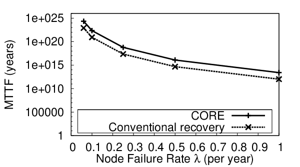
We use as an example to compare the MTTFs of CORE and conventional recovery. MTTF is determined by three variables: storage capacity of each node , transfer rate and node failure rate . First, we fix the mean failure time 4 years [36] and 1TB, and evaluate the impact of on the MTTFs. Figure 9(a) shows the MTTF results. With the increasing transfer rate, the recovery rate and hence the MTTFs of both CORE and conventional recovery increase. Next, we fix Gbps and 1TB, and evaluate the impact of on the MTTFs. Figure 9(b) shows the results. Both CORE and conventional recovery see a decreasing MTTF as increases. From both Figures 9(a) and 9(b), CORE has a larger MTTF than conventional recovery (by 10-100 times), since it has a higher recovery rate with less recovery bandwidth. For example, considering 1TB, 1Gbps and 0.25, the MTTF of CORE is 26 of that of conventional recovery.

 |
 |
| (a) MTTF vs. transfer rate | (b) MTTF vs. node failure rate |
5 Implementation
We complement our theoretical analysis with prototype implementation. As a proof of concept, we implement CORE as an extension to the Hadoop Distributed File System (HDFS) [41]. We modify the source code of HDFS and its erasure code module HDFS-RAID [20]. We point out that CORE is also applicable for general large-scale distributed storage systems.
5.1 Overview of HDFS-RAID
By default, HDFS uses 3-way replication to achieve data availability. To provide data availability with smaller storage overhead, HDFS-RAID is designed to convert replicas into erasure-coded data and stripe the erasure-coded data across different nodes. We call it the striping operation.
HDFS-RAID uses a distributed RAID file system (DRFS) that manages the erasure-coded data stored in HDFS. In the original HDFS design, the basic data unit of the read/write operation is called a block (see Section 2.1). There are a single NameNode and multiple DataNodes. The NameNode stores the metadata for HDFS blocks, while the DataNodes store HDFS blocks. On top of HDFS, HDFS-RAID adds a new node called the RaidNode, which performs the striping operation. It also periodically checks any lost blocks, and if needed, performs the recovery operation for those blocks. Also, HDFS-RAID provides a client-side interface called DRFS client, which handles all read/write requests for the erasure-coded data stored in HDFS. If a lost block is requested, then it performs degraded reads to the lost block. Both the RaidNode and the DRFS client have an ErasureCode module, which performs the encoding/decoding operations for the erasure-coded data.
The striping operation is carried out as follows. For a given , the RaidNode first downloads a group of blocks (from one of the replicas for each block). It then encodes the blocks into blocks on a per-stripe basis (see Section 2.1). The blocks are then placed on DataNodes. Unused replicas of the blocks will later be removed from HDFS. The RaidNode repeats the same process for another group of blocks.
5.2 Integration into HDFS-RAID
To integrate our relayer model into HDFS-RAID, we can simply deploy a relayer daemon in the RaidNode and the DRFS client for failure recovery and degraded reads, respectively. CORE is implemented on HDFS release 0.22.0 with HDFS-RAID enabled. We modify both the RaidNode and the DRFS client accordingly to support concurrent recovery. Since regenerating codes need DataNodes to generate encoded symbols during recovery, we add a signal handler in each DataNode to respond to the request of encoded symbols. During recovery, the RaidNode or the DRFS client notifies the surviving DataNodes about the identities of the failed nodes, and the DataNodes accordingly generate the encoded symbols.
Optimizations of coding. In our current prototype, we implement RS codes [35] and IA codes [42] as candidates of erasure codes and regenerating codes, respectively. We implement them in the ErasureCode module of HDFS-RAID. To minimize the computational overhead of the encoding/decoding operations, we implement the coding schemes in C++ using the Jerasure library [32], and have the ErasureCode module execute a specific coding scheme through the Java Native Interface (note that HDFS-RAID is written in Java). For each code we implement, we add XOR transformation [3], which changes all encoding/decoding operations into purely XOR operations, and XOR scheduling [19], which reduces the number of redundant XOR operations during encoding/decoding. Both XOR transformation and XOR scheduling are available in the Jerasure library [32].
Pipelined model. The original HDFS-RAID uses a single-threaded implementation. For further speedup, we implement a pipelined model that leverages multi-threading to parallelize the encoding/decoding operations. Figure 10 shows the implementation of our pipelined design in CORE, assuming that a single failure is to be recovered. The RaidNode requests metadata from the NameNode (Steps 1-2) and downloads blocks from the surviving nodes (Steps 3-4). Then the RaidNode reconstructs the lost data using the pipelined implementation, which is composed of three stages. First, we have an input thread that collects data from the surviving DataNodes. The input thread then dispatches the data via a shared ring buffer to the worker thread, which reconstructs the lost data for the failed nodes. In the case of regenerating codes, the worker thread fetches the encoded symbols of one stripe from the ring buffer. It decodes the encoded symbols corresponding to the stripe and reconstructs the lost strips for the failed nodes. It sends the reconstructed strips to an output thread, and processes another stripe. The output thread then collects all reconstructed stripes and uploads the resulting blocks (Step 5).

6 Prototype Experiments
We experiment CORE on a distributed storage system testbed. A major deployment issue is that the overall recovery performance is determined by a combination of factors including network bandwidth, disk I/Os, encoding/decoding overhead. We address the following questions: (i) Does minimizing recovery bandwidth play a key role in improving the overall recovery performance (see Section 6.1)? (ii) Can CORE preserve the performance of the normal striping operation offered by HDFS-RAID (see Section 6.2)? (iii) How much can CORE improve the performance of recovery, degraded reads, and MapReduce (see Sections 6.3-6.5)?
We conduct our experiments on an HDFS testbed with one NameNode and up to 20 DataNodes being used. Each node runs on a quad-core PC equipped with an Intel Core i5-2400 3.10GHz CPU, 8GB RAM, and a Seagate ST31000524AS 7200RPM 1TB SATA harddisk. All machines are equipped with a 1Gb/s Ethernet card and interconnected over a 1Gb/s Ethernet switch. They all run Linux Ubuntu 12.04.
We compare RS codes [35], which use conventional recovery, and CORE, which builds on IA codes [42] (see Section 5.2). Both codes are implemented in C++ and compiled with GCC 4.6.3 with the -O3 option. Our microbenchmark results (see Section 6.1) are averaged over 10 runs, while other macrobenchmark results are averaged over five runs.
 |
 |
 |
| (a) RS, | (b) RS, | (c) RS, |
 |
 |
 |
| (d) CORE, | (e) CORE, | (f) CORE, |
6.1 Microbenchmark Studies
In this subsection, we conduct microbenchmark studies on the recovery operation. We first evaluate the encoding/decoding performance versus the symbol size. We then provide a breakdown analysis on different recovery steps.
Encoding/decoding performance in reconstruction. To evaluate the computational encoding/decoding overhead of RS codes and CORE in recovery, we measure how fast the relayer decodes the symbols downloaded from surviving nodes and reconstructs the lost data. Since the encoding/decoding operations are performed over symbols (see Section 2.1), our goal here is to study how the symbol size affects the encoding/decoding performance in reconstruction.
We vary the symbol size from 8 bytes to 32KB. Our evaluation operates on 30 stripes of data for different sets of . To stress test the computational encoding/decoding performance, we eliminate the impact of disk I/Os by first loading the data that is to be downloaded by the relayer for recovery into memory. We then measure the time for performing all encoding/decoding operations on the in-memory data for reconstruction. We compute the reconstruction throughput, which is defined as the size of the lost data divided by the reconstruction time.
Figure 11 shows the reconstruction throughput for one to three failures for RS codes and CORE. Larger implies more failures can be tolerated, but has smaller reconstruction throughput since the generator matrix becomes larger and there is higher encoding/decoding overhead. Note that the throughput trend versus the symbol size also conforms to the results of different erasure codes in the study [32]. The throughput initially increases with the symbol size, and reaches maximum when the symbol size is around 4KB to 8KB. When the symbol size further increases, the throughput drops because of cache misses [32].
RS codes have higher reconstruction throughput than CORE (which builds on IA codes). The reason is that the strip size of regenerating codes is (see Section 2.3), while we can implement erasure codes with . For the same , the generator matrix of regenerating codes is larger than that of erasure codes (see Section 2.1). Nevertheless, in all cases we consider, CORE has at least 500MB/s of reconstruction throughput at symbol size 8KB. Our following benchmark results show that the reconstruction performance is not the bottleneck in the recovery operation.
Breakdown analysis. Recall from Figure 2 that a recovery operation can be decomposed into five different steps. We now conduct a simplified analysis on the expected performance of each recovery step in RS codes and CORE. Our goal is to identify the bottleneck, and hence justify the need of minimizing recovery bandwidth.
We fix the storage capacity of each node to be 1GB. Suppose that we recover failed nodes with a total of GB of data, and that is used. We collect the system parameters based on the measurements on our testbed hardware, and derive the expected time for each recovery step as shown in Table 2. We elaborate our derivations as follows.
- •
I/O step. In both RS codes and CORE, each surviving node reads all its stored data. For our disk model, our measurements (using the Linux command hdparm) indicate that the disk read speed is 116MB/s. Suppose that all surviving nodes read data in parallel. In the I/O step, both schemes take 1GB116MB/s 8.83s.
- •
Encode step. In RS codes, surviving nodes do not perform encoding, while in CORE, surviving nodes encode their stored data. Suppose that all surviving nodes perform the encode step in parallel. Our measurements indicate that the encoding time on an i5-2400 machine is no more than 0.4 seconds for 1GB of raw data.
- •
Download step. The relayer downloads data from other surviving nodes via its 1Gb/s interface, so its effective transfer rate must be upper bounded by 1Gb/s (or 125MB/s). For RS codes, the relayer always downloads the same amount of original data, which is 1GB = 10GB. For CORE, we consider only the good failure patterns, which account for the majority of cases (see Section 4.4). From Theorem 1, the relayer downloads GB of data (where ). We can derive the (minimum) download times for RS codes and CORE accordingly. In reality, the effective transfer rate is lower than 1Gb/s and the download times will be higher.
- •
Reconstruction step. We fix the symbol size at 8KB, in which both RS codes and CORE can achieve high reconstruction throughput according to our previous experiments. The reconstruction throughput values of RS codes are 594-789MB/s, while those of CORE are 523-585MB/s. We derive the reconstruction times by dividing GB by the reconstruction throughput for failures.
- •
Upload step. The relayer uploads GB of reconstructed data via its 1Gb/s interface. We derive the upload times as in the download step.
From our derivations, we see that the download step uses the most time among all operations. Since we can pipeline the download, reconstruction, and upload steps in the relayer, we can see that the download step is the bottleneck. This justifies the need of minimizing recovery bandwidth, which we define as the amount of data transferred in the download step.
| time(s) | RS | RS | RS | CORE | CORE | CORE |
|---|---|---|---|---|---|---|
| I/O | 8.83 | 8.83 | 8.83 | 8.83 | 8.83 | 8.83 |
| Encode | 0 | 0 | 0 | 0.12 | 0.23 | 0.35 |
| Download | 81.92 | 81.92 | 81.92 | 15.56 | 29.49 | 41.78 |
| Reconstruct | 1.30 | 2.75 | 5.17 | 1.75 | 3.69 | 5.87 |
| Upload | 8.19 | 16.38 | 24.58 | 8.19 | 16.38 | 24.58 |
6.2 Striping
We now evaluate the striping operation that is originally provided by HDFS-RAID when encoding replicas with RS codes and IA codes (used by CORE). We also compare our pipelined implementation with the original single-threaded implementation in HDFS-RAID. Our goal is to show that CORE, when using IA codes, maintains the striping performance when compared to RS codes.
For a given , we configure our HDFS testbed with DataNodes, one of which also deploys the RaidNode. We prepare a GB of original data as our input. By our observation, the input size is large enough to give a steady throughput. HDFS first stores the file with the default 3-replication scheme. Then the RaidNode stripes the replica data into encoded data using either RS codes or IA codes. The encoded data is stored in DataNodes. We rotate node identities when we place the blocks so that the parity blocks are evenly distributed across different DataNodes to achieve load balancing. We fix the symbol size at 8KB. We use the default HDFS block size at 64MB, but for some , we alter the block size slightly to make it a multiple of the strip size (which is 8KB) for IA codes. We measure the striping throughput as the original size of data divided by the total time for the entire striping operation.
Figure 12 shows the striping throughput results. By parallelizing the data transfer and encoding/decoding steps, our pipelined implementation improves the striping throughput by around 50% over the original single-threaded implementation in HDFS-RAID. We see that IA codes have smaller striping throughput than RS codes in both implementations. In single-threaded implementation, IA codes have higher encoding/decoding overhead and hence show worse performance. In pipelined implementation, IA codes have strip size and contain more symbols per stripe than RS codes with strip size . Our pipelined implementation will not start the encoding thread until the RaidNode downloads the first stripe of symbols for each group of blocks (see Section 5.1). Thus, RS codes benefit more from parallelization. However, the throughput drop in IA codes is small, by at most 6.1% only in our pipelined implementation.

6.3 Recovery
We evaluate the recovery performance. We first stripe encoded data across DataNodes as in Section 6.2. Then we manually delete all blocks stored on DataNodes to mimic failures, where . Since we rotate node identities when we stripe data, the lost blocks of the failed DataNodes include both data and parity blocks. The RaidNode recovers the failures and uploads reconstructed blocks to new DataNodes (same as the failed DataNodes in our evaluation). Here, we deploy the RaidNode in one of the new DataNodes. We measure the recovery throughput as the total size of lost blocks divided by the total recovery time.

Figure 13 shows the recovery throughput results. Both RS codes and CORE see higher throughput for larger as more lost blocks are recovered. Overall, CORE shows significantly higher throughput than RS codes. The throughput gain is the highest in (20,10). For example, for single failures, the gain is 3.45; for concurrent failures, the gains are 2.33 and 1.75 for and , respectively.
Our experimental results are fairly consistent with our analytical results in Section 4.4. For example, in (20,10), the ratio of the reconstruction bandwidth of CORE to that of erasure codes for and are 0.36 and 0.51, respectively (see Figure 7(a)). These results translate to the recovery throughput gains of CORE at 2.78 and 1.96, respectively. Our experimental results show slightly less gains, mainly due to disk I/O and encoding/decoding overheads that are not captured in the recovery bandwidth.
6.4 Degraded Reads
We further evaluate the degraded read performance in the presence of transient failures. The evaluation setting is the same as that of the recovery operation described in Section 6.3, except that the degraded read operation is now performed by the DRFS client. Suppose that nodes fail, where . We have the DRFS client request a lost HDFS block on one of the failed DataNodes. The lost block will be reconstructed from the data of other surviving DataNodes. Here, we deploy the DRFS client in one of the failed DataNodes. We measure the degraded read throughput, defined as the amount of data being requested divided by the response time.
Figure 14 shows the degraded read throughput results. RS codes keep almost the same throughput for each , as they always download blocks for reconstruction. Overall, CORE shows a throughput gain in degraded reads. For example, if we consider the (20,10) code, CORE shows degraded throughput gain of 3.75, 2.34 and 1.70 for , , and , respectively.
We point out that our concurrent reconstruction is optimized for reconstructing lost blocks on failures. If only one lost block is reconstructed while , it is possible to use even less reconstruction bandwidth. Nevertheless, our results still show the improvements of our concurrent reconstruction over the conventional one.

6.5 Runtime of MapReduce with Node Failures
MapReduce [8] is an important data-processing framework running on top of HDFS. Here, we conduct preliminary evaluation on how CORE affects the performance of a MapReduce job with node failures.
We run a classical WordCount job using MapReduce to count the words in a document collection. The WordCount job runs a number of tasks of two types: a map task reads a block from HDFS and emits each word to a reduce task, which then aggregates the results of multiple map tasks. With node failures, some map tasks may perform degraded reads to the unavailable blocks.
We consider the same evaluation settings as in Section 6.4. Here, we focus on (20,10). We run a WordCount job on 10GB of plain text data obtained from the Gutenburg website [17]. Using CORE or RS codes, we stripe the encoded blocks across DataNodes, disable nodes to simulate a -node failure, and then run the WordCount job on the encoded data. We also consider the baseline MapReduce job when there is no failure. We use the default MapReduce scheduler to schedule tasks across DataNodes. We measure the runtime performance of different MapReduce components: (i) the average runtime of a normal map task running on the available data of normal nodes, (ii) the average runtime a degraded map task running on the unavailable data of failed nodes, (iii) the average runtime of a reduce task, and (iv) the overall runtime of the WordCount job.
| baseline | CORE | RS | CORE | RS | CORE | RS | |
|---|---|---|---|---|---|---|---|
| map task (normal) | 20.48 | 20.43 | 20.43 | 20.46 | 20.44 | 20.55 | 20.54 |
| map task (degraded) | NA | 23.39 | 32.83 | 24.23 | 31.30 | 27.19 | 33.14 |
| reduce task | 30.10 | 31.21 | 31.39 | 31.42 | 31.12 | 31.25 | 30.73 |
| overall | 209.20 | 212.40 | 216.20 | 216.60 | 231.20 | 231.00 | 242.80 |
Table 3 shows the runtime of different MapReduce components. For the normal map tasks and the reduce tasks, their runtimes are almost identical to the baseline, meaning that CORE does not have adverse effects to such tasks. The degraded map task incurs a longer time than the baseline due to degraded reads. Nevertheless, CORE outperforms RS codes in this item. For 1, 2 and 3, CORE takes 29%, 22% and 18% less time than RS codes to run a degraded map task. The results also conform to our theoretical findings. The extra runtime of the degraded map task over the normal map task is mainly due to the degraded read request. Consider . For RS codes, the extra runtime is 12.4s, while for CORE, the extra runtime is 2.96s (or 80% less). This is consistent with our analysis results in Section 4.4.
CORE also improves the overall runtime of the WordCount job, although the improvement is less significant due to other overheads. On the other hand, we expect that the improvement of CORE becomes more significant in a large-scale distributed setting where network bandwidth is limited. We argue that the MapReduce evaluation here is preliminary. We plan to consider more workloads and testbed environments in future work.
7 Related Work
We review related work on the recovery problem for erasure codes and regenerating codes.
Minimizing I/Os. Several studies focus on minimizing I/Os required for recovering a single failure in erasure codes. Their approaches mainly focus on a disk array system where the disk access is the bottleneck. Authors of [43, 44] propose optimal single failure recovery for RAID-6 codes. Khan et al. [27] show that finding the optimal recovery solution for arbitrary erasure codes is NP-hard. Note that the performance gains of the above solutions over the conventional recovery are generally less than 30%, while regenerating codes achieve a much higher gain in single failure recovery (see Section 6).
Authors of [23, 12, 31, 36]33 3 Although the proposed scheme of [12] is also called CORE, it refers to Cross Object Redundancy and builds on local recovery codes, which have very different constructions from regenerating codes considered by our work. have proposed local recovery codes that reduce bandwidth and I/O when recovering lost data. They evaluate the codes atop a cloud storage system simulator (e.g., in [31]), Azure Storage (e.g., in [23]) and HDFS (e.g., in [12, 36]). It is worth noting that the local recovery codes are non-MDS codes with additional parities added to storage, so as to trade for better recovery performance. All these studies focus on optimizing single failure recovery. Our work differs from them in several aspects: (i) we consider optimal minimum storage regenerating codes that are MDS codes, (ii) we consider recovering both single and concurrent failures, (iii) we experiment regenerating codes that require storage nodes to perform encoding operations.
Minimizing recovery bandwidth. Regenerating codes [10] minimize the recovery bandwidth for a single failure in a distributed storage system. There have been many theoretical studies on constructing regenerating codes (e.g., [10, 34, 33, 38, 42]). In contrast with the above solutions that minimize I/Os, most regenerating codes typically read all stored data to generate encoded data. Implementation studies of regenerating codes recently receive attention from the research community, such as [11, 21, 24, 25]. Note that the studies [11, 24, 25] do not integrate regeneration codes into a real storage system, while NCCloud [21] implements a storage prototype based on non-systematic regenerating codes.
Cooperative recovery. Several theoretical studies (e.g., [22, 26, 39, 40]) address concurrent failure recovery based on regenerating codes, and they focus on recovery of lost data on new nodes. They all consider a cooperative model, in which the new nodes exchange among themselves their data being read from surviving nodes during recovery. Authors of [22, 26] prove that the cooperative model achieves the same optimal recovery bandwidth as ours, but they do not provide explicit constructions of regenerating codes that achieve the optimal point. Authors of [39, 40] provide such explicit implementations, but they focus on limited parameters and the resulting implementations do not provide any bandwidth saving over erasure codes. A drawback of the cooperative model requires coordination among the new nodes to perform recovery, and its implementation complexities are unknown. Extending it for degraded reads is also non-trivial, as clients simply request lost data instead of recovering lost data on new nodes.
8 Discussion
In this section, we discuss several open issues that are not covered in this paper.
High redundancy of CORE. In this paper, we consider the MSR codes with fairly high redundancy (i.e., double redundancy), due to the requirements imposed by the underlying constructions of optimal exact regenerating codes. It is shown in [38] that all linear MSR codes with exact recovery must satisfy the condition . Other codes may be constructed via the non-systematic, functional regenerating codes [10], which are suited to the rarely-read data. How to extend CORE for functional regenerating codes remain an open issue in this work.
Concurrent recovery of non-MDS codes. We consider the concurrent recovery problem of MSR codes, which achieve the minimum storage efficiency as in MDS codes (see Section 2.1). One may consider the non-MDS codes, which incurs higher storage overhead but achieve better single failure recovery performance (e.g. MBR codes [34] and local recovery codes [23, 12, 31, 36]). An open issue is how to extend these non-MDS codes to support efficient concurrent recovery.
Wide-area storage systems. We currently implement CORE atop HDFS. We plan to explore the implementation of CORE in wide-area storage systems (e.g., [2, 6, 7, 28]), where network bandwidth is limited and the benefits of regenerating codes should become more prominent. Also, one side benefit of CORE is that we can delay recovery until the number of failed nodes reaches some threshold so as to we avoid recovering transient failures that are commonly found in wide-area networks [2, 5, 30].
9 Conclusions
We address the reconstruction problem in a distributed storage system in the presence of single and concurrent failures, from both theoretical and applied perspectives. We explore the use of regenerating codes (or network coding) to provide fault-tolerant storage and minimize the bandwidth of data transfer during reconstruction. We propose a system CORE, which generalizes existing optimal single-failure-based regenerating codes to support the recoveries of both single and concurrent failures. We theoretically show that CORE minimizes the reconstruction bandwidth in most concurrent failure patterns. Our scheme adopts a relayer model that can be easily integrated into real storage systems. To demonstrate, we prototype CORE as a layer atop Hadoop HDFS, and show via testbed experiments that we can speed up both recovery and degraded read operations. The source code of our CORE prototype is available for download at: http://ansrlab.cse.cuhk.edu.hk/software/core.
References
- [1] R. Ahlswede, N. Cai, S. Li, and R. Yeung. Network Information Flow. IEEE Trans. on Information Theory, 46(4):1204–1216, Jul 2000.
- [2] R. Bhagwan, K. Tati, Y. Cheng, S. Savage, and G. Voelker. Total Recall: System Support for Automated Availability Management. In Proc. of USENIX NSDI, Oct 2004.
- [3] J. Bloemer, M. Kalfane, R. Karp, M. Karpinski, M. Luby, and D. Zuckerman. An XOR-based Erasure-Resilient Coding Scheme. Technical report, The International Computer Science Institute, Berkeley, CA,, Aug 1995.
- [4] B. Calder, J. Wang, A. Ogus, N. Nilakantan, A. Skjolsvold, S. McKelvie, Y. Xu, S. Srivastav, J. Wu, H. Simitci, et al. Windows Azure Storage: A Highly Available Cloud Storage Service with Strong Consistency. In Proc. of ACM SOSP, Oct 2011.
- [5] B. Chun, F. Dabek, A. Haeberlen, E. Sit, H. Weatherspoon, M. Kaashoek, J. Kubiatowicz, and R. Morris. Efficient Replica Maintenance for Distributed Storage Systems. In Proc. of USENIX NSDI, May 2006.
- [6] Cleversafe. http://www.cleversafe.com.
- [7] F. Dabek, M. Kaashoek, D. Karger, R. Morris, and I. Stoica. Wide-Area Cooperative Storage with CFS. ACM SIGOPS Operating Systems Review, 35(5):202–215, Dec 2001.
- [8] J. Dean and S. Ghemawat. MapReduce: Simplified Data Processing on Large Clusters. In Proc. of USENIX OSDI, Dec 2004.
- [9] G. DeCandia, D. Hastorun, M. Jampani, G. Kakulapati, A. Lakshman, A. Pilchin, S. Sivasubramanian, P. Vosshall, and W. Vogels. Dynamo: Amazon’s Highly Available Key-Value Store. In Proc. of ACM SOSP, 2007.
- [10] A. Dimakis, P. Godfrey, Y. Wu, M. Wainwright, and K. Ramchandran. Network Coding for Distributed Storage Systems. IEEE Trans. on Information Theory, 56(9):4539–4551, Sep 2010.
- [11] A. Duminuco and E. Biersack. A Practical Study of Regenerating Codes for Peer-to-Peer Backup Systems. In Proc. of IEEE ICDCS. IEEE, Jun 2009.
- [12] K. Esmaili, P. Lluis, and A. Datta. The CORE Storage Primitive: Cross-Object Redundancy for Efficient Data Repair & Access in Erasure Coded Storage. arXiv, preprint arXiv:1302.5192, 2013.
- [13] D. Ford, F. Labelle, F. I. Popovici, M. Stokel, V.-A. Truong, L. Barroso, C. Grimes, and S. Quinlan. Availability in Globally Distributed Storage Systems. In Proc. of USENIX OSDI, Oct 2010.
- [14] S. Ghemawat, H. Gobioff, and S. Leung. The Google File System. In Proc. of ACM SOSP, Dec 2003.
- [15] K. Greenan. Reliability and Power-Efficiency in Erasure-Coded Storage Systems. PhD thesis, University of California, Santa Cruz, 2009.
- [16] K. M. Greenan, E. L. Miller, and T. J. E. Schwarz. Optimizing Galois Field Arithmetic for Diverse Processor Architectures and Applications. In Proc. of IEEE MASCOTS, 2008.
- [17] Gutenberg. http://www.gutenberg.org/.
- [18] A. Haeberlen, A. Mislove, and P. Druschel. Glacier: Highly Durable, Decentralized Storage Despite Massive Correlated Failures. In Proc. of USENIX NSDI, May 2005.
- [19] J. Hafner, V. Deenadhayalan, K. Rao, and J. Tomlin. Matrix Methods for Lost Data Reconstruction in Erasure Codes. In Proc. of USENIX FAST, Dec 2005.
- [20] HDFS-RAID. http://wiki.apache.org/hadoop/HDFS-RAID.
- [21] Y. Hu, H. Chen, P. Lee, and Y. Tang. NCCloud: Applying Network Coding for the Storage Repair in a Cloud-of-Clouds. In Proc. of USENIX FAST, Feb 2012.
- [22] Y. Hu, Y. Xu, X. Wang, C. Zhan, and P. Li. Cooperative Recovery of Distributed Storage Systems from Multiple Losses with Network Coding. IEEE Journal on Selected Areas in Communications (JSAC), 28(2):268–276, Feb 2010.
- [23] C. Huang, H. Simitci, Y. Xu, A. Ogus, B. Calder, P. Gopalan, J. Li, and S. Yekhanin. Erasure Coding in Windows Azure Storage. In Proc. of USENIX ATC, Jun 2012.
- [24] Z. Huang, E. Biersack, and Y. Peng. Reducing Repair Traffic in P2P Backup Systems: Exact Regenerating Codes on Hierarchical Codes. ACM Trans. on Storage, 7(3):10, Oct 2011.
- [25] S. Jiekak, A.-M. Kermarrec, N. L. Scouarnec, G. Straub, and A. Van Kempen. Regenerating Codes: A System Perspective. CoRR, abs/1204.5028, 2012.
- [26] A. Kermarrec, N. Le Scouarnec, and G. Straub. Repairing Multiple Failures with Coordinated and Adaptive Regenerating Codes. In Proc. of NetCod, Jun 2011.
- [27] O. Khan, R. Burns, J. Plank, W. Pierce, and C. Huang. Rethinking Erasure Codes for Cloud File Systems: Minimizing I/O for Recovery and Degraded Reads. In Proc. of USENIX FAST, Feb 2012.
- [28] J. Kubiatowicz, D. Bindel, Y. Chen, S. Czerwinski, P. Eaton, D. Geels, R. Gummadi, S. Rhea, H. Weatherspoon, W. Weimer, C. Wells, and B. Zhao. OceanStore: An Architecture for Global-Scale Persistent Storage. In Proc. of ACM ASPLOS-IX, Nov 2000.
- [29] R. Li, J. Lin, and P. P. C. Lee. CORE: Augmenting Regenerating-Coding-Based Recovery for Single and Concurrent Failures in Distributed Storage Systems. In Proc. of IEEE MSST, May 2013. [online] http://www.cse.cuhk.edu.hk/~pclee/www/pubs/msst13.pdf.
- [30] S. Nath, H. Yu, P. B. Gibbons, and S. Seshan. Subtleties in Tolerating Correlated Failures in Wide-area Storage Systems. In Proc. of USENIX NSDI, May 2006.
- [31] D. Papailiopoulos, J. Luo, A. Dimakis, C. Huang, and J. Li. Simple Regenerating Codes: Network Coding for Cloud Storage. In Proc. of IEEE INFOCOM, Mar 2012.
- [32] J. Plank, J. Luo, C. Schuman, L. Xu, and Z. Wilcox-O’Hearn. A Performance Evaluation and Examination of Open-Source Erasure Coding Libraries for Storage. In Proc. of USENIX FAST, Feb 2009.
- [33] K. Rashmi, N. Shah, and P. Kumar. Optimal Exact-Regenerating Codes for Distributed Storage at the MSR and MBR Points via a Product-Matrix Construction. IEEE Trans. on Information Theory, 57(8):5227–5239, Aug 2011.
- [34] K. Rashmi, N. Shah, P. Kumar, and K. Ramchandran. Explicit Construction of Optimal Exact Regenerating Codes for Distributed Storage. In Proc. of Allerton Conf., Sep 2009.
- [35] I. Reed and G. Solomon. Polynomial Codes over Certain Finite Fields. Journal of the Society for Industrial and Applied Mathematics, 8(2):300–304, Jun 1960.
- [36] M. Sathiamoorthy, M. Asteris, D. Papailiopoulos, A. G. Dimakis, R. Vadali, S. Chen, and D. Borthakur. XORing Elephants: Novel Erasure Codes for Big Data. Proc. of VLDB Endowment, 2013.
- [37] B. Schroeder and G. A. Gibson. Disk Failures in the Real World: What Does an MTTF of 1,000,000 Hours Mean to You? In Proc. of USENIX FAST, Feb 2007.
- [38] N. Shah, K. Rashmi, P. Kumar, and K. Ramchandran. Interference Alignment in Regenerating Codes for Distributed Storage: Necessity and Code Constructions. IEEE Trans. on Information Theory, 58(99):2134 – 2158, Apr 2012.
- [39] K. Shum. Cooperative Regenerating Codes for Distributed Storage Systems. In Proc. of IEEE ICC, Jun 2011.
- [40] K. Shum and Y. Hu. Exact Minimum-Repair-Bandwidth Cooperative Regenerating Codes for Distributed Storage Systems. In Proc. of IEEE Int. Symp. on Information Theory (ISIT), Jul 2011.
- [41] K. Shvachko, H. Kuang, S. Radia, and R. Chansler. The Hadoop Distributed File System. In Proc. of IEEE MSST, May 2010.
- [42] C. Suh and K. Ramchandran. Exact-Repair MDS Code Construction using Interference Alignment. IEEE Trans. on Information Theory, 57(3):1425–1442, Mar 2011.
- [43] Z. Wang, A. Dimakis, and J. Bruck. Rebuilding for Array Codes in Distributed Storage Systems. In IEEE GLOBECOM Workshops, Dec 2010.
- [44] L. Xiang, Y. Xu, J. Lui, Q. Chang, Y. Pan, and R. Li. A Hybrid Approach to Failed Disk Recovery Using RAID-6 Codes: Algorithms and Performance Evaluation. ACM Trans. on Storage, 7(3):11, Oct 2011.
Appendix
Proof of Theorem 1
We can formally build our proof based on the analysis of the information flow graph as in [10]. Here, we only show the main idea. Let be the number of surviving nodes from which the relayer downloads data for recovery. Let be the amount of data downloaded (per stripe) from each of the surviving nodes to recover failed nodes. We assume that the reconstructed data will be stored on new nodes, which contain a total of units of information.
We first consider . Due to the MDS property, we can restore the original data from any out of nodes, each storing units of data. For example, we can select a set of any originally surviving nodes (denoted by set ) and a set of any new nodes (denoted by set ) for some . The total amount of useful information must be at least in order for the original data to be restorable. However, contains units of information derived from . By excluding the redundant information, we require:
The left side is minimum when . Thus, the recovery bandwidth (i.e., ) must be at least . To minimize the recovery bandwidth with respect to , we set and the result follows.
When , any out of the new nodes must be able to restore the
original data due to the MDS property. Thus, the new nodes must contain
units of useful information, which can be reconstructed by downloading data
from any surviving nodes as in erasure codes. The recovery
bandwidth is .
Proof of Theorem 2
Since MSR codes achieve the lower bound of recovery bandwidth for single failure recovery, the amount of data downloaded from each surviving node is [10] (see Equation (1)).
Consider . CORE in essence performs single failure recoveries based
on MSR codes, and in each recovery we actually download
units of data from each of the surviving nodes. If the failure pattern
is good, then we can recover the virtual symbols and hence the lost data. The
lower bound is hit for . For , we can simply download
units of data from any surviving nodes and any failure pattern can
be recovered. The result follows.