Short-time Fourier transform laser Doppler holography
Abstract
We report a demonstration of laser Doppler holography at a sustained acquisition rate of 250 Hz on a 1 Megapixel complementary metal–oxide–semiconductor (CMOS) sensor array and image display at 10 Hz frame rate. The holograms are optically acquired in off-axis configuration, with a frequency-shifted reference beam. Wide-field imaging of optical fluctuations in a 250 Hz frequency band is achieved by turning time-domain samplings to the dual domain via short-time temporal Fourier transformation. The measurement band can be positioned freely within the low radio-frequency (RF) spectrum by tuning the frequency of the reference beam in real-time. Video-rate image rendering is achieved by streamline image processing with commodity computer graphics hardware. This experimental scheme is validated by a non-contact vibrometry experiment.
Though effective for single-point analysis [1], laser Doppler measurements are more difficult to perform in wide-field imaging configuration, because of a technological challenge : digital image frames have to be read out at kHz rates and beyond to perform short-time discrete Fourier transforms (DFT) [2]. Recently, image-plane laser Doppler recordings with a high throughput CMOS camera in conjunction with short-time DFT calculations by a field programmable gate array (FPGA) reportedly enabled continuous monitoring of blood perfusion in the mm/s range. Full-field flow maps of 480 480 pixels were rendered at a rate of 14 Hz, obtained from image recordings at a frame rate of 14.9 kHz [3]. For transient dynamics imaging of faster phenomena, high throughput laser Doppler schemes were designed by multipoint [4] or time multiplexing [5] approaches. High speed holography enabled offline vibrometry from time-resolved optical phase measurements [6]. Heterodyne holography, as a variant of time-averaged holography [7, 8] with a strobe [9] or a frequency-shifted reference beam [10, 11], is appropriate for steady-state (at the scale of the exposure time) mechanical vibrations mapping. Advances in reconstruction techniques of optically-measured digital holograms with Graphics Processing Units (GPUs) [12, 13] have led to real-time holographic screening of a single vibration frequency, demonstrated in this regime [14].
In this letter, we report an experimental demonstration of video-rate image reconstruction and display of laser fluctuation spectra from high speed holographic measurements. Sustained Fresnel reconstruction of off-axis holograms at 250 Hz and 10 Hz rendering by short-time DFTs is performed. Images and RF spectra of a thin metal plate’s out-of-plane vibration modes around 3.2 kHz are presented.
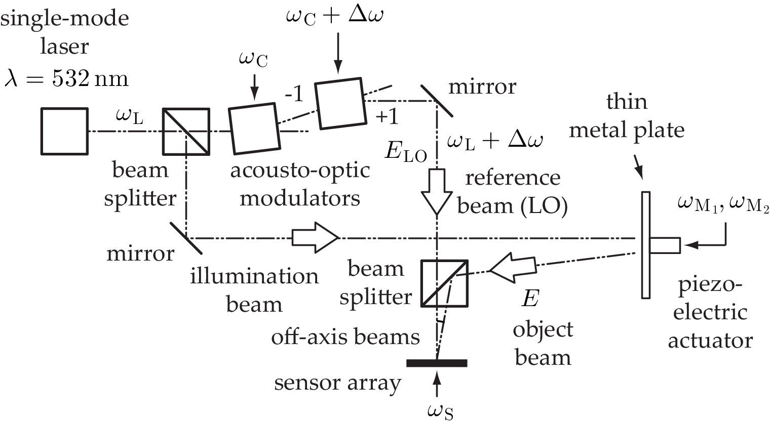
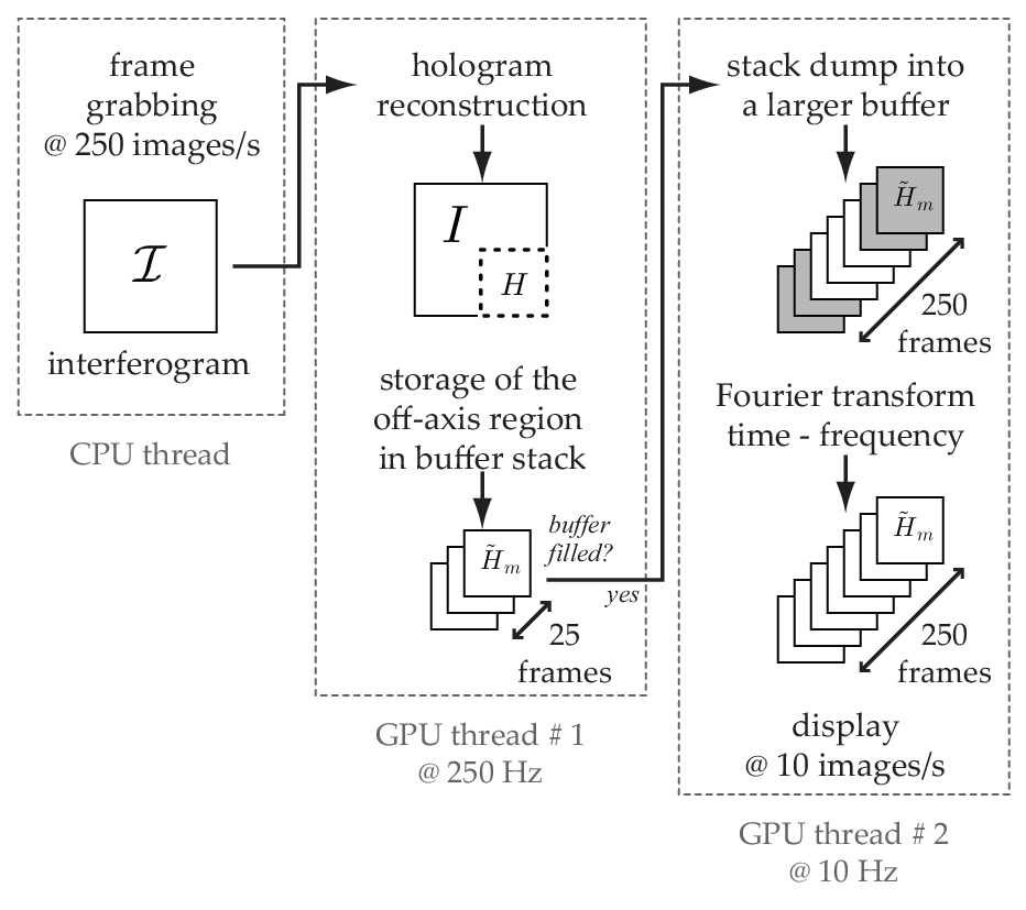
The optical setup, sketched in fig.1, is similar to the one reported in the demonstration of video-rate vibrometry at a single frequency [14], at a difference that a high throughput CMOS camera is used to achieve megapixel recordings at 250 frames per second. An off-axis, frequency-shifted Mach-Zehnder interferometer is used to perform a multipixel heterodyne detection of an object field beating against a separate local oscillator (LO) field , in reflective geometry. The main optical radiation field is provided by a 100 mW, single-mode laser (wavelength nm, optical frequency , Oxxius SLIM 532). The optical frequency of the LO beam is shifted by an arbitrary quantity in the low RF range by two acousto-optic modulators (AA-electronics, MT80-A1.5-VIS). The object studied is a thin metal plate with hexagonal holes, shined over with 50 mW of impinging light. It is excited with a piezo-electric actuator (PZT, Thorlabs AE0505D08F), vibrating sinusoidally, driven at 10 V. The structure’s vibrations provoke a local phase modulation (eq.7) of the backscattered optical field . Interference patterns are measured with a Basler A504k camera (Micron MV13 progressive scan CMOS sensor array of pixels, quantum efficiency 25 % at 532 nm). The camera is run in external trigger mode at , at 8 bit/pixel quantization. Images of the central pixels region are recorded. The image acquisition is interfaced with a National Instruments NI PCIe-1433 frame grabber. Each raw interferogram digitally acquired at time , noted is dumped to a frame buffer in the GPU RAM of a NVidia GTX 580 graphics card by a CPU thread (fig. 2). The object field of complex amplitude is noted
| (1) |
where and is the fluctuating phase, as a result of optical path length modulation. The acousto-optic modulators enable the optical LO field of complex amplitude to be detuned by
| (2) |
Holographic image rendering from each recorded interferogram is performed with a numerical Fresnel transform. The hologram , back-propagated to the object plane, is calculated by forming the Fast Fourier Transform (FFT) of the product of with a quadratic phase map, depending on the relative curvature of the wavefronts of and in the sensor plane [15]. This calculation is handled by the GPU (thread #1, Fig. 2), by an algorithm elaborated with Microsoft Visual C++ 2008 and NVIDIA’s Compute Unified Device Architecture (CUDA) software development kit 3.2, on single precision floating point arrays. The practical implementation of free-space propagation with a discrete Fresnel transform [8] yields complex-valued holograms carried by the cross-terms of the interference pattern reconstructed in the object plane. In off-axis configuration [16], the zero-order terms and and the twin-image term can be filtered-out. After filtering, the remaining complex-valued contribution to the off-axis hologram is
| (3) |
The heterodyne spectrum of the radiation field is detected by a short-time discrete Fourier transform (DFT) of over consecutive samples (fig. 2, thread # 2), 10 times per second. The -th Fourier component of the DFT,
| (4) |
is a heterodyne measurement of the laser fluctuation spectrum at time , at frequency
| (5) |
The discrete frequencies of the measured spectra lie within the Nyquist limits of the camera bandwidth , while the LO detuning frequency can be set arbitrarily by the acousto-optic modulators (fig. 3).


We assessed the thin metal plate’s out-of-plane vibration modes around 3.2 kHz with the presented holographic approach. The metallic structure was excited sinusoidally at one () or two () frequencies and . In either case, the resulting out-of-plane motion at a given point of the surface of the plate, considered as a linear medium for acoustic waves, is
| (6) |
where and are the angular frequency and the local amplitude of each component, respectively. The phase modulation of the backscattered light is
| (7) |
where . The temporal part of the field undergoing sinusoidal phase modulation can be decomposed in a basis of Bessel functions with the Jacobi–Anger identity. If , the object field is
| (8) |
where is the Bessel function of the first kind of rank . The only remaining low frequency, camera-filtered term in eq. 3 beating around , within the Nyquist domain (i.e. for ) is
| (9) |
This modulated hologram yields a single component in the short-time DFT spectrum , at the frequency . In the first part of the movie (media 1, when ), the excitation frequency was swept from 3210 Hz to 3290 Hz, and the LO was detuned by ; the measurement frequency of the short-time DFT was swept concurrently from 10 Hz to 90 Hz, in 5 Hz steps. The reported spectra result from the magnitude averaged within the red square superimposed on the vibration maps.
The metallic structure was then excited sinusoidally at two frequencies : , and . The object field undergoing phase modulation from a double excitation ( in eq. 7) takes the form
| (10) |
The terms of eq. 3 modulated at frequencies within the camera bandwidth are actually measured. The others are filtered out. The temporal part of the camera-filtered hologram reduces to the low frequency component
| (11) |
where
| (12) |
Eq.11 yields the frequency comb observed in fig.4(g), whose peaks are separated by . In the second part of the movie reported in media 1, the first excitation frequency was set to , the second one was swept from to , in 5 Hz steps. The frequency comb broadened with in accordance with equations 11 and 12. For a larger frequency difference , only two lines of the comb are visible (fig.4(e,f)).
In conclusion, we performed laser Doppler imaging from sustained sampling of 1 Mega pixel interferograms at a throughput of 250 Mega bytes per second, and rendering of 0.25 Mega pixel off-axis heterodyne holograms by short-time discrete Fourier transform with a refreshment rate of 10 Hz. This demonstration was made with commodity computer graphics hardware. We reported video-rate optical monitoring of out-of-plane vibration amplitudes in a frequency band of 250 Hz, shifted by 3.2 kHz from DC. This demonstration opens the way to high bandwidth laser Doppler holography in real time.
We thank Francois Bruno and Fiona Quinlan-Pluck careful rereading of the manuscript. We gratefully acknowledge support from Fondation Pierre-Gilles de Gennes (FPGG014), Agence Nationale de la Recherche (ANR-09-JCJC-0113, ANR-11-EMMA-046), région Île-de-France (C’Nano, AIMA), and the ”investments for the future” program (LabEx WIFI: ANR-10-IDEX-0001-02 PSL*).
References
- [1] P. Castellini, M. Martarelli, and EP Tomasini. Laser doppler vibrometry: Development of advanced solutions answering to technology’s needs. Mechanical Systems and Signal Processing, 20(6):1265–1285, 2006.
- [2] J.B. Allen and L.R. Rabiner. A unified approach to short-time fourier analysis and synthesis. Proceedings of the IEEE, 65(11):1558–1564, 1977.
- [3] M. Leutenegger, E. Martin-Williams, P. Harbi, T. Thacher, W. Raffoul, M. André, A. Lopez, P. Lasser, and T. Lasser. Real-time full field laser doppler imaging. Biomedical Optics Express, 2(6):1470–1477, 2011.
- [4] J.M. Kilpatrick and V. Markov. Matrix laser vibrometer for transient modal imaging and rapid non-destructive testing. Proc. of SPIE, 7098:709809, 2008.
- [5] Y. Fu, M. Guo, and P. B. Phua. Multipoint laser doppler vibrometry with single detector: principles, implementations, and signal analyses. Appl. Opt., 50(10):1280–1288, Apr 2011.
- [6] Giancarlo Pedrini, Wolfgang Osten, and Mikhail E. Gusev. High-speed digital holographic interferometry for vibration measurement. Appl. Opt., 45(15):3456–3462, May 2006.
- [7] R. L. Powell and K. A. Stetson. Interferometric vibration analysis by wavefront reconstruction. J. Opt. Soc. Am., 55:1593, 1965.
- [8] P. Picart, J. Leval, D. Mounier, and S. Gougeon. Time-averaged digital holography. Opt. Lett., 28:1900–1902, 2003.
- [9] P. Hariharan, B. F. Oreb, and C. H. Freund. Stroboscopic holographic interferometry: measurements of vector components of a vibration. Appl. Opt., 26(18):3899–3903, Sep 1987.
- [10] C. C. Aleksoff. Temporally modulated holography. Applied Optics, 10:1329–1341, 1971.
- [11] F. Joud, F. Verpillat, F. Laloë, M. Atlan, J. Hare, and M. Gross. Fringe-free holographic measurements of large-amplitude vibrations. Opt. Lett., 34(23):3698–3700, 2009.
- [12] Tomoyoshi Shimobaba, Yoshikuni Sato, Junya Miura, Mai Takenouchi, and Tomoyoshi Ito. Real-time digital holographic microscopy using the graphic processing unit. Opt. Express, 16(16):11776–11781, 2008.
- [13] Lukas Ahrenberg, Andrew J. Page, Bryan M. Hennelly, John B. McDonald, and Thomas J. Naughton. Using commodity graphics hardware for real-time digital hologram view-reconstruction. J. Display Technol., 5(4):111–119, 2009.
- [14] Benjamin Samson, Frédéric Verpillat, Michel Gross, and Michael Atlan. Video-rate laser doppler vibrometry by heterodyne holography. Opt. Lett., 36(8):1449–1451, Apr 2011.
- [15] Nicolas Verrier and Michael Atlan. Off-axis digital hologram reconstruction: some practical considerations. Appl. Opt., 50(34):H136–H146, Dec 2011.
- [16] Etienne Cuche, Pierre Marquet, and Christian Depeursinge. Spatial filtering for zero-order and twin-image elimination in digital off-axis holography. Applied Optics, 39(23):4070, 2000.