A Wireless Channel Sounding System for Rapid Propagation Measurements
Abstract
Wireless systems are getting deployed in many new environments with different antenna heights, frequency bands and multipath conditions. This has led to an increasing demand for more channel measurements to understand wireless propagation in specific environments and assist deployment engineering. We design and implement a rapid wireless channel sounding system, using the Universal Software Radio Peripheral (USRP) and GNU Radio software, to address these demands. Our design measures channel propagation characteristics simultaneously from multiple transmitter locations. The system consists of multiple battery-powered transmitters and receivers. Therefore, we can set-up the channel sounder rapidly at a field location and measure expeditiously by analyzing different transmitters’ signals during a single walk or drive through the environment. Our design can be used for both indoor and outdoor channel measurements in the frequency range of MHz to GHz. We expect that the proposed approach, with a few further refinements, can transform the task of propagation measurement as a routine part of day-to-day wireless network engineering11 1 (c) 2012 AT&T Intellectual Property. All rights reserved..
I Introduction
Radio propagation measurement is essential for developing propagation models [1] and crucial for deploying and maintaining operational systems. There are numerous path loss and delay spread models based on measurements made in a variety of environments, using different transmitter heights and carrier frequencies [2, 3, 4, 5, 6, 7]. However, most models have substantial errors when compared to reality [8], due to the complicated nature of wireless propagation through complex environments. Besides, a new environment to deploy wireless systems (e.g., small-cell systems with low base stations in urban areas), often requires a measurement campaign to determine if existing models can be adapted to it, and if so, what parameters must be changed.
In deployment of wireless systems in complex, high-value locations (such as dense urban areas, or unique and complex buildings), propagation modelling or even ray-tracing prediction tools may not account for important and unpredictable realities of target locations. At least spot verifications of the modelling outputs and calibrations, by means of a small measurement campaign, may be required. In addition, sophisticated modeling approaches [6, 7] may require 3D models of the environment or the associated material properties, which may be difficult and expensive to obtain and yet may not account for hidden metal structures or openings.
In short, it would be ideal if wireless propagation measurements were so simple, inexpensive and quick that measuring an environment would often be the first choice by radio engineers, rather than modeling and verifying. Short of that ideal goal, we argue that the current wireless channel measurement practices can be made far simpler and quicker so that more measurements can be taken at modest cost to support further modelling, design and deployment efforts. We would like to achieve this without sacrificing too much in accuracy or scope of measured parameters, compared to the conventional channel measurement campaigns using laboratory equipment or custom-built apparatus.
In this paper, we describe our first effort in designing a rapid wireless channel sounding system. We also mention our rapid prototyping exercise that was enabled by the recent advancements of software-defined radio (SDR) technologies. We use Universal Software Radio Peripheral (USRP) [9] and GNU Radio [10] as the SDR platform. We perform sliding correlator and frequency domain channel sounding in indoor and outdoor experiments respectively.
II A CASE FOR RAPID CHANNEL SOUNDING SYSTEM
II-A Limits of propagation models
Most easy-to-use channel models [2, 3, 4, 5] are statistical in nature, and thus almost certain to have errors at specific locations. More location-specific modelling approaches such as ray-tracing [7] or partition-based models [6] require more detailed information on the environment. In all cases, at least some measurements are often required for calibration and verification. Some complex deployment environments might benefit from more extensive measurements, if such measurements can be made rapidly and cheaply by field personnel without extensive training.
II-B Benefits of using multiple transmitters
An important decision during deployment engineering would be where to place base stations in a given environment, given coverage and capacity requirements. Using multiple transmitters at many candidate locations emitting reference signals that can be distinguished by the receiver, a single walk or drive through the environment enables rapid measurements taken for all candidate locations. Also, if the effect of different antenna heights, carrier frequencies, antenna types or mounting arrangements need to be measured, multiple transmitters can be set up with different parameters of interest to quickly measure during a single run through the areas of interest.
II-C Essential features
II-C1 Reference signals
The reference signals from multiple transmitters should be distinguishable even when their respective received power levels differ by large amounts at the receiver, as the receiver can be close to one transmitter while measuring a far-away transmitter at the same time.
II-C2 Battery-powered operation
Arranging power supply to many transmitter locations before starting measurements can be burdensome in most environments. Thus, the fixed transmitters must be battery-powered for several hours with a reasonably-sized battery.
II-C3 Small form factor
To further ease the preparation and measurement, the transmitters and the receivers should be reasonably small and light so that they can be quickly and safely placed or mounted on desired locations.
II-C4 Low cost
Having to use multiple transmitters and receivers, it would be desirable to keep the cost of individual units low.
II-C5 Flexibility
The approach should be flexible to support channel measurement across a wide frequency region.
II-D Our contributions
Our approach incorporates the simultaneous measurement of channel propagation characteristics from multiple transmitter locations. Previous works in the related literature [1, 11, 12, 13, 6, 14] focused on channel sounding measurements from a single transmitter location. To the best of our knowledge, ours is the only work in the literature that implements multiple transmitter simultaneous channel sounding.
Traditional channel sounding systems use expensive measurement equipment like vector network analyzers [11, 12], vector signal generators [8], spread spectrum channel sounders [6], etc. Due to the open source GNU Radio software and inexpensive USRP radios, our proposed channel sounding system costs significantly less than these systems.
The carrier frequency of the USRP daughterboards can be varied from megahertz (MHz) to gigahertz (GHz). Therefore, our approach can perform channel measurements in this wide frequency range.

III Measurement System
We use GNU Radio software and USRP daughterboards in the channel sounding experiments. The top and bottom parts of Fig. 1 show the transmit and receive block diagrams of the USRP respectively. In the transmitter side, the host processor sends complex baseband samples to the field programmable gate array (FPGA) through an ethernet cable. The FPGA board low pass filters and up-converts the signal to a higher sampling rate. Thereafter, the signal goes through the digital-to-analog converter (DAC) and passband frequency conversion stage to the transmitter antenna. The receiver side operates exactly in the opposite manner.
The host processor views these complex baseband samples as floating point numbers. GNU Radio is an open source software that allows the use of digital signal processing algorithms on these floating point numbers.
We use USRP networked (N) and embedded (E) series radios for our indoor and outdoor experiments respectively. The N series requires an external laptop for operation. On the other hand, the E series radios contain an embedded processor and can work as stand-alone pre-programmed transceivers. USRP radios can offer up to 400 megasample per second (MS/s) and 100 MS/s sampling rate in the DAC and analog-to-digital converter (ADC) respectively. However, the speed bottleneck of the GNU Radio software usually comes from the host processor speed and the capacity of the ethernet cable. The N series and E series software allow up to 50 MS/s and 8 MS/s data transfer rate from the host processor respectively. The N and E series are used in sliding correlator and frequency domain channel sounding systems respectively.
IV Sliding Correlator Channel Sounding
IV-A Methodology
In the sliding correlator approach, the transmitters send a pseudo-noise (PN) sequence with a nanosecond (ns) pulse duration and the receiver obtains the wideband path loss and multipath delay profile. The upper and lower parts of Fig. 2 uses a single transmitter and receiver to show the transmit and receive diagrams of the sliding correlator system respectively .
IV-A1 Transmission
The transmitter sends , a Galois linear feedback shift register (GLFSR) maximal length PN sequence of degree 10. can be analytically written as follows:
| (1) |
where, and is a chip sequence of length 1023, . Here, takes the value of either or . Defining as the correlation output of and and using the properties of PN sequence,
| (2) |
The signal is passed through a root raised cosine (RRC) filter and then sent to the real input of the USRP transmitter module. The imaginary input comes from a null source. The USRP transmitter module sends the complex baseband samples to the USRP transmit path and establishes the transmit frequency and sampling rate. The baseband equivalent transmitted signal is given by:
| (3) |
where is the period of the RRC generated pulse.

IV-A2 Multipath Channel
The impulse response of the multipath channel can be written as:
| (4) |
Here, is the number of multipaths in the channel. is the complex gain of each multipath and is the associated delay. We assume since we focus on relative delay.
| Parameter | Value |
|---|---|
| Pathloss dynamic range | 45-105 dB |
| Temporal resolution | 60 ns |
| Maximum multipath delay | 61 millisecond |
IV-A3 Reception
The baseband equivalent received signal, in time domain, is obtained by:
| (5) |
goes through the USRP receive path, gets sampled and arrives at the USRP receiver module of Fig. 2. The time synchronizer block finds the proper phase of the RRC pulses. A detailed theoretical description of the time synchronizer can be found in [15] and the open source code description can be found in [16]. Proper timing synchronization leads to the following discrete received signal ,
| (6) |
Equation (6) follows from (3) and (5). Assume that the multipath delay is an integer multiple of the pulse period . With this assumption, where is a non-negative integer. The properties of the RRC filter suggest that if [17]. Therefore,
| (7) | |||||
Now, the correlator block produces,
| (8) |
where, . Using (2) in (8), one can easily find the complex multipath gain at delay, . For example, lead to the calculation of whereas, lead to . The multipath power-delay profile can be obtained from the powers of the individual multipath components . The path loss can be found from the difference of the known transmit power and the total power in the multipath components ().
Our approach probes the channel only at the integer multiples of the pulse duration, . However, the multipath rays can arrive at other times, as well. Therefore, our observation at time is actually an effect of multipath at nearby times. The author of [18] theoretically estimates the number of arrival paths and the associated attenuation and delay from the channel gain at the integer multiples of the pulse duration. The implementation of [18] in GNU Radio USRP framework remains an area of future research.
| Parameter | Value |
|---|---|
| Pathloss dynamic range | 45-120 dB |
| Frequency separation | 2 MHz |
| Number of steps | 10 |
| Temporal resolution | 27.8 ns |
IV-B Multiple transmitter sliding correlator channel sounding algorithm
Different transmitters repeatedly access their allotted time slots and transmit the GLFSR PN sequence. The receiver captures the PN sequences from each transmitter and finds the path loss and delay profile for each of them. The overall algorithm is summarized below:
- 1.
Assume there are transmitters. Transmitter transmits in the desired frequency band during the time slot . Here, is the allotted time slot length of each transmitter during each time period and . Also, is the total experiment duration.
- 2.
The user opens the floor map image in the receiver laptop and clicks a point that corresponds to the present location. The receiver flow graph is initiated at time where is the nearest integer.
- 3.
The receiver captures the samples during the time slot , splits the floating point numbers into segments and uses the segment to calculate the path loss and delay profile of the transmitter.
- 4.
The wideband path loss, delay profile and X & Y coordinates of the location are stored in the laptop.

IV-C Challenges of multiple transmitter channel sounding in the sliding correlator method
IV-C1 Time synchronization
We use the USRP N series radios, controlled by external laptops, in the sliding correlator channel sounding method. The clock timing of these laptops is synchronized in advance through network time protocol (NTP) servers [19]. The synchronized laptops control the TDMA operation of the multiple transmitters.
IV-C2 Near-far effect
In an ideal transmitter TDMA system, transmitters remain silent when one transmits. In order to implement this method in our setup, the USRP radios have to either turn off or transmit null source during the active transmission period of the other radio. The frequent turn on-and-off leads to the freezing up of USRP radios. On the other hand, USRP radios leak a small amount of power while transmitting a null source. This leakage power leads to the classical near-far problem in a multiple transmitter scenario, i.e., the channel measurements of the far transmitter get overwhelmed by the leakage from the near transmitter, due to the large difference of path loss among the transmitters. In order to avoid these two problems, we take the following approach: when transmitter transmits, transmitter transmits in the industrial, scientific and medical radio band at the lowest power possible. The receiver receives samples in the desired frequency band and therefore, the channel measurements of different transmitters remain independent of each other.
The design parameters of the sliding correlator channel sounder are given in Table I.
V Frequency Domain Channel Sounding
The USRP N series radio based sliding correlator channel sounding system requires an external laptop for each transmitter and receiver. The use of an external laptop in outdoor environments is inconvenient due to its heavy weight and limited battery lifetime. Therefore, we use USRP E series transmitters in outdoor experiments. The embedded processor of E series radios can provide sampling rates up to 8 MS/s. In a sliding correlator channel sounding system, this sampling rate limits the temporal resolution to ns. This resolution is too low to handle the rich multipath delay spread of an outdoor environment. Therefore, we perform frequency domain channel sounding in outdoor experiments.
V-A Methodology
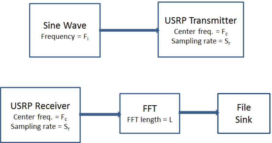
In the frequency domain channel sounding method, the transmitters and the receiver synchronously sweep a given frequency band in discrete steps of . By sweeping a large frequency band, one can obtain a very fine temporal resolution [11]. The top and bottom parts of Fig. 3 show the transmitter and receiver block diagrams of a frequency domain channel sounder using a single transmitter and receiver.
V-B Multiple transmitter frequency domain channel sounding algorithm

Assume that there are carrier frequency steps and transmitters. There is a predefined list of carrier frequencies, and sinusoidal frequencies, .
- 1.
The USRP clocks of the transmitters and the receiver get time synchronized on-the-fly through global positioning system (GPS) [20].
- 2.
Transmitter steps through the carrier frequency list and transmits a sinusoidal tone at frequencies in steps.
- 3.
The receiver synchronously steps through the carrier frequency list with sampling rate and performs an FFT of length on the received samples.
- 4.
Transmitter ’s signal falls in the bin of the FFT. The narrowband path loss of the transmitter at frequencies is found based on the power in the corresponding bin.
V-C Challenges of multiple transmitter channel sounding in the frequency domain method
Theoretically, a large number of complex sine waves can be accommodated in the Nyquist transmission band . However, some of the power in a tone from a given transmitter can leak into adjacent frequency regions due to phase noise and other imperfections. Hence, the transmitters’ sinusoidal tones need to be separated by a guard band so that the path loss calculations of different transmitters remain independent of each other. This guard band, along with the maximum sampling rate of the receiver, limits the maximum number of transmitters to 5-6 in one time frame. However, separation of the transmitters in both time and frequency domain, can accommodate a large number of transmitters in the frequency domain channel sounding method.
V-D Mean wideband path loss
The frequency domain approach provides narrowband path losses in the frequency range . The wideband path loss in this frequency band can be obtained by taking the average of the individual path losses.
The design parameters of the frequency domain channel sounder are given in Table II.
VI Experimental Results

VI-A Sliding correlator channel sounding results
The indoor channel measurements were obtained using the sliding correlator system. The measurements were performed in the frequency band near MHz. The experiment was set up in the 5th floor of Building A of AT&T’s Middletown facility. Three transmitters were set up in different parts of a wing and the receiver moved through the wing. A total of simultaneous channel sounding measurements for the three transmitters were made. The wideband path loss and the multipath delay profile of each transmitter were stored for each location. The X & Y coordinates of the floor map image, corresponding to the measurement location, were saved, as well.
Fig. 4 and Fig. 5 plot the wideband path loss of two transmitters as a heat map on the floor plan layout of the wing. The X & Y ticks in Fig. 4-7 denote distances in meters. In all these figures, the star and the circles show the transmitter and measurement locations respectively. The height of the indoor transmitter 1, 2 and the receiver were , and inches from the floor level.
Fig. 4 and 5 show that the path loss becomes higher as the receiver moves away from the transmitter. Since transmitter 2 is placed in the central location of the wing, the mean path loss from transmitter 2 is lower than that from transmitter 1. Therefore, transmitter 2 will require less power than transmitter 1 to cover the whole wing.
The RMS delay spreads, averaged across all the measurement points in the wing, were found to be ns and ns for transmitter and respectively. We skip presenting the delay profiles of the measurement locations for brevity.
VI-B Frequency domain channel sounding results

The outdoor channel measurements were obtained using the frequency domain channel sounding system. The measurements were performed in ten discrete steps of MHz and in the frequency band near MHz. The experiment was set up in the courtyard of Building A of AT&T’s Middletown facility. Two transmitters were set up in two different corners of the courtyard. In total, channel sounding measurements were taken simultaneously for each transmitter in different locations of this court yard. The height of the outdoor transmitter 1, 2 and the receiver were 6, 12 & 3 feet respectively from the ground level. The ten narrowband path loss measurements of each transmitter were stored for each location. The GPS location [20] and the X & Y coordinates in the satellite image view were saved, as well.
Fig. 6 and 7 plot the mean wideband path loss of outdoor transmitter 1 and 2 as a heat map on the satellite image view of the courtyard. A comparison between Fig. 4 & 5 and Fig. 6 & 7 reveals that the outdoor path losses decrease less rapidly than the indoor ones. This happens because the outdoor signal does not get attenuated through any wall.
We now focus on variation in the narrowband path losses across the frequency band. The star, diamond and circle shapes in Fig. 8 show the locations of outdoor transmitter , transmitter and the receiver respectively for a particular measurement. Fig. 9 shows the path loss spectrum of transmitter and at the receiver location. The path loss from transmitter varies only by dB in the MHz band. This happens since the receiver is located very close to transmitter 2 and therefore, it does not experience much multipath from transmitter 2. On the other hand, the receiver is located in a far and non-line-of-sight location from transmitter 1. Therefore, it experiences rich multipath from transmitter 1 due to the nearby buildings and foliage. Fig. 9 shows that the path loss from transmitter 1 varies by dB across the frequency band.

VII Conclusion
We design and implement rapid wireless channel sounding systems, using both sliding correlator and frequency domain approaches. Our design measures the channel propagation characteristics simultaneously from multiple transmitter locations. Thus, the proposed design allows researchers to quickly verify channel models with real data. It also assists engineers to compare the coverage of multiple transmitter sites with a single run of measurements.
Our achieved temporal resolution ( ns) in the sliding correlator method is limited by the data transfer rate of the ethernet interface. The implementation of our algorithm directly on the USRP FPGA will avoid this bottleneck and obtain a temporal resolution of ns. This extension remains an area of future research.
For simplicity and time, we decided to design without explicit coordination between transmitters and receivers. Our future efforts will focus on more coordination through explicit communication to dynamically change power, timing, frequency, and other aspects of the system.
VIII Acknowledgements
We thank the members of the GNU Radio mailing list for their continuous support throughout the project.
References
- [1] D. Cox, “Delay doppler characteristics of multipath propagation at 910 mhz in a suburban mobile radio environment,” IEEE Transactions on Antennas and Propagation, vol. 20(5), pp. 625–635, Sept. 1972.
- [2] M. Hata, “Empirical formula for propagation loss in land mobile radio services,” IEEE Transactions on Vehicular Technology, vol. 29(3), pp. 317–325, Aug. 1980.
- [3] K. Herring, J. Holloway, D. Staelin, and D. Bliss, “Path-loss characteristics of urban wireless channels,” IEEE Transactions on Antennas and Propagation, vol. 58(1), pp. 171–177, Jan. 2010.
- [4] “The ITS irregular terrain model,” accessed September 2012, http://flattop.its.bldrdoc.gov/itm.html.
- [5] D. J. Cichon and T. Kurner, “Digital mobile radio towards future generation systems: cost 231 final report,” Action 231, European Cooperation in the Field of Scientific and Technical Research, 1993.
- [6] G. Durgin, T. Rappaport, and H. Xu, “Measurements and models for radio path loss and penetration loss in and around homes and trees at 5.85ghz,” IEEE Transactions on Communications, vol. 46(11), pp. 1484–1495, Aug. 1998.
- [7] V. Sridhara and S. Bohacek, “Realistic propagation simulation of urban mesh networks,” Computer Networks, vol. 51(12), pp. 3392–3412, Aug. 2007.
- [8] D. Sicker C. Phillips and D. Grunwald, “Bounding the error of path loss models,” in Proc. IEEE Symposium on New Frontiers in Dynamic Spectrum Access Networks (DySPAN), May 2011, pp. 71–82.
- [9] “ETTUS research,” accessed September 2012, http://www.ettus.com.
- [10] “GNU Radio Website,” accessed September 2012, http://www.gnuradio.org.
- [11] S. S. Ghassemzadeh, R. Jana, C. W. Rice, W. Turin, and V. Tarokh, “Measurement and modeling of an ultra-wide bandwidth indoor channel,” IEEE Transactions on Communications, vol. 52(10), pp. 1786–1796, Oct. 2004.
- [12] S. J. Howard, K. Pahlavan, R. Co, and M. A.Marlboro, “Measurement and analysis of the indoor radio channel in the frequency domain,” IEEE Transactions on Instrumentation and Measurement, vol. 39(5), pp. 751–755, Oct. 1990.
- [13] D. Porrat, “UHF propagation in indoor hallways,” IEEE Transactions on Wireless Communications, vol. 3(4), pp. 1188–1198, July 2004.
- [14] M. H. Firooz, J. Zhang, N. Patwari, and S. K. Kasera, “Channel sounding for the masses: Low complexity gnu 802.11b channel impulse response estimation,” IEEE Transactions on Wireless Communications, vol. 11(1), pp. 1–8, Jan. 2012.
- [15] F. J. Harris, Multirate Signal Processing for Communication Systems, Prentice Hall, Upper Saddle River, NJ, 2008.
- [16] “GNUradio polyphase time synchronizer,” accessed September 2012, http://gnuradio.org/doc/doxygen/.
- [17] J. G. Proakis, Digital Communications, Mcgraw Hills, New York, NY, 2001.
- [18] J. Fuchs, “Multipath time-delay detection and estimation,” IEEE Transactions on Signal Processing, vol. 47(1), pp. 237–243, Jan. 1999.
- [19] “Network Time Protocol Server List,” accessed September 2012, http://tf.nist.gov/tf-cgi/servers.cgi.
- [20] “GPS synchronization,” accessed September 2012, http://www.gpsinformation.org/dale/nmea.htm.