Low-field microwave absorption in epitaxial La0.7Sr0.3MnO3 films resulting from the angle-tuned ferromagnetic resonance in the multidomain state
Abstract
We studied magnetic-field induced microwave absorption in 100-200 nm thick La0.7Sr0.3MnO3 films on SrTiO3 substrate and found a low-field absorption with a very peculiar angular dependence: it appears only in the oblique field and is absent both in the parallel and in the perpendicular orientations. We demonstrate that this low-field absorption results from the ferromagnetic resonance in the multidomain state (domain-mode resonance). Its unusual angular dependence arises from the interplay between the parallel component of the magnetic field that drives the film into multidomain state and the perpendicular field component that controls the domain width through its effect on domain wall energy. The low-field microwave absorption in the multidomain state can be a tool to probe domain structure in magnetic films with in-plane magnetization.
Keywords:
ferromagnetic resonance, magnetic domains, microwave absorption, manganite, thin filmpacs
76.50+g, 75.60.Ch, 75.78.Fg, 75.47.GkI introduction
Low-field microwave absorption is a useful tool of detection of magnetic transitions in bulk materials and thin films [1, 2, 3]. It is also known as nonresonant, zero-field, or magnetically-modulated microwave absorption and it was used to find the traces of ferromagnetic and superconducting phases in bulk materials [1, 4]. The low-field absorption in magnetic materials has multiple sources that operate in different frequency ranges [5]. The dominant contribution at radiofrequencies arises from magnetoimpedance [6, 7, 8] (the field dependence of the skin-depth) and domain wall resonances [9, 10, 11], while at microwave frequencies it is commonly attributed to various ferromagnetic resonances in the magnetically unsaturated state. These include non-aligned FMR mode [12, 13], the natural FMR [14], off-resonant absorption associated with the FMR tail [15, 16], and the domain mode resonances [17, 18, 19, 20, 21, 22, 23, 24, 25]. Magnetoresistive absorption in conducting ferromagnetics contributes at all frequencies and is most spectacular at the field when magnetization changes abruptly, namely at zero field [26, 27] and upon transition from the unsaturated to saturated state [28, 29, 30, 31, 32].
Manganites are conducting ferromagnetics with exceptionally high magnetoresistance [33]. Their microwave properties in magnetic field have been extensively studied and the low-field microwave absorption was found in many compounds. While the dominant contribution in bulk manganites arises from magnetoimpedance [14, 34] there are many observations of the low-field microwave absorption in thin films that can’t be explained in this way. Some of these observations were attributed to magnetoresistance in the magnetically-unsaturated state [8, 35, 36] while the origin of others [37, 38, 32, 14] is unclear.
Here, we studied microwave absorption in high-quality epitaxial La0.7Sr0.3MnO3 (LSMO) films in the presence of magnetic field and observed the low-field microwave absorption peak with a very peculiar angular dependence: it appears only in the oblique field. We show that this peak is not related to magnetoresistance but arises from the ferromagnetic resonance in the multidomain state.
II Domain mode resonance in a thin film with ”easy-plane” anisotropy in the oblique magnetic field
The theory of the ferromagnetic resonance in the multidomain state was originally developed in relation to bubble or stripe domains in ferromagnetic films with out-of-plane anisotropy [17, 21, 20, 19]. The few studies of films with in-plane magnetization were restricted to the case of uniaxial anisotropy and parallel field orientation [18, 19]. Here, we consider a ferromagnetic film with biaxial easy-plane anisotropy in oblique field and calculate its high-frequency susceptibility following the approach of Refs. [18, 20, 19].
II.1 Magnetostatics
Consider a thin ferromagnetic film in oblique magnetic field (Fig.1). Its free energy is
| (1) |
where and are the in-plane and out-of-plane anisotropy energies, is the energy associated with domain walls and stray field of domains, is the Zeeman energy, and absorbs all contributions that do not depend on field orientation. We assume a strong easy-plane anisotropy, , and a weak in-plane anisotropy, . Here, is the saturation magnetization, is the effective demagnetizing factor that includes both the shape and the crystalline anisotropies, are hard axes and is the (positive) in-plane anisotropy constant, whereas . We assume that the external field has only and components, in such a way that the field projection on the film plane is parallel to one of the in-plane hard axes.

Figure 1 schematically shows the magnetic structure of the film when the external field slowly decreases to zero. At high field the film is in the single domain state, the magnetization lies in the plane (Fig.1a,b), and . At lower field the magnetization deviates towards the in-plane easy axes (which lie at 450 to and -axes) and . The film splits onto parallel domains with domain walls in the plane (Fig.1c). When the field is nearly perpendicular to the film, the resulting magnetic structure is not clear. We believe that the film exhibits an irregular domain pattern (Fig.1d).
Consider the structure shown in Fig.1c. Magnetizations of the adjacent domains, , have the same magnitude but different orientation. The free energy of a domain is:
| (2) |
where are the demagnetizing factors in the and directions, is the magnetization, are projections of the field onto and axes, and is the Lagrange multiplier. The contribution of the domain wall energy and stray field of domains was neglected. The effective field is
| (3) |
A similar expression holds for . The equilibrium condition, , yields magnetization components and
| (4) |
where indices 1,2 were dropped. The single domain state corresponds to , while the multidomain state corresponds to finite and . The onset of the multidomain state occurs when and . Equation 4 yields the field that corresponds to the onset of the domain state,
| (5) |
where and are the parallel and the perpendicular anisotropy fields. For weak in-plane anisotropy, , Eq.5 yields for , and for where is the critical angle that delineates between two regimes that exhibit different domain patterns.
- •
Oblique field, . Upon decreasing field the film goes from the magnetically-saturated to the unsaturated state when the following condition is met: . At lower field when the film goes into multidomain state and splits into parallel domains. The preferential direction of the domain walls is determined by the field projection onto the film plane (Fig.1,c).
- •
Nearly perpendicular orientation, . When the film goes from the magnetically-saturated to unsaturated state at , the second condition, , is already met. The in-plane component of the external field at the onset of the domain state is too small to impose preferential orientation of the domain walls, hence the film most probably splits into irregular domain pattern (Fig.1d).
II.2 Domain mode resonance
To derive the dynamic response of the film with parallel domains to the microwave magnetic field oriented along the domain walls (Fig.1c) we use the Landau-Lifshitz equation without damping
| (6) |
where is the gyromagnetic ratio. We consider the microwave field as a small perturbation that induces rotation of magnetization of each domain, in other words we assume where is the static equilibrium magnetization and is a small time-dependent contribution. The effective field also acquires small dynamic contribution, , where is given by Eq.3. We linearize Eqs.3,6 and find the dynamic effective field:
| (7) |
A similar expression holds for domain 2. Solution of Eqs. 6,7 yields two eigenfrequencies
| (8) |
| (9) |
Since magnetization in the unsaturated state is almost parallel to the film, we can simplify these cumbersome expressions by omitting the terms with . Equations 8, 9 reduce to:
| (10) |
| (11) |
Both eigenfrequencies depend on external field (through ) and go to zero at the onset of the domain state where . The lower frequency, , almost does not depend on the domain structure since in this ”acoustic” mode the magnetizations of neighboring domains precess almost in phase. On the other hand, the higher frequency, , depends on the domain shape (through the demagnetizing factor ) since in this ”optical” mode the magnetizations of neighboring domains precess in antiphase and the resulting magnetization has poles on the domain walls. The complex susceptibility
| (12) |
exhibits resonance at . The resonant frequency can be crudely estimated from Eq.11,
| (13) |
Since the domain demagnetizing factors are where is the film thickness and is the domain width [18], Eq.13 yields (we neglected here the contribution of stress and crystallographic anisotropy to ). When the field is decreased to zero the magnetization in domains rotate (affecting ), domain width also changes, in such a way that and, correspondingly, the microwave susceptibility (Eq.12) can pass through the resonance. For nearly perpendicular field orientation, when the film splits into irregular domains (Fig.1d) such resonance is impeded.
Although the above model assumes that the field projection on the film plane is exactly along the hard magnetization axis (Fig.1) this assumption is probably not too restrictive. To observe the domain mode resonance it is necessary to have a system of parallel domains with alternating magnetizations and the component of the microwave magnetic field parallel to the domain walls. This requirement can be satisfied when the field projection on the film considerably deviates from the hard magnetization axis, especially for the films with biaxial in-plane anisotropy.

III Experiment and comparison to model
III.1 Experimental procedure
To measure the low-field microwave absorption associated with the domain mode resonance we used a bipolar -band Bruker ESR spectrometer, a resonant cavity, and an Oxford helium flow cryostat (Fig.2). We studied La0.7Sr0.3MnO3 films with thicknesses 50, 100, 150, and 200 nm. The films were grown by the pulsed laser deposition technique on the mm3 (001) SrTiO3 substrates in two different laboratories [39, 40] and have of 330 K. The FMR measurements in the parallel field showed biaxial (four-fold) in-plane anisotropy of all these epitaxial films. We measured magnetically-modulated microwave absorption and dispersion in mm2 pieces of these films when the magnetic field was swept from large negative to large positive values (typically, from -10 kOe to 10 kOe). To change the field orientation with respect to the film we rotated the sample whereas the microwave magnetic field was always parallel to the film plane and perpendicular to the dc magnetic field. To find the exact perpendicular orientation we slightly tilted the sample holder in different directions, measured the field of the ferromagnetic resonance (FMR), and found the orientation in which the resonant field attained its maximum value. In what follows we focus on the results for the different pieces of the 200 nm thick film. We got similar results for the 100 nm and 150 nm thick films but not for the 50 nm thick film. According to our interpretation this difference can be related to the different domain structure in thin films whose thickness is comparable to the domain wall width.

III.2 Low-field microwave absorption at 295 K
Figure 3 shows derivative microwave absorption in oblique field for the 200 nm thick film and for two opposite directions of the field sweep. The narrow peaks at 7.6 kOe arise from the ferromagnetic and spin-wave resonances, the baseline arises from magnetoresistance, the pronounced zero-field feature exhibiting hysteresis is attributed to domain mode resonance. This zero-field feature does not depend on the magnitude (1-10 Oe) or frequency of the modulation field (1-100 kHz).


Figure 4 shows corresponding integrated absorption and dispersion (details of the integration procedure are in Ref. [36]). The absorption baseline linearly increasing with field arises from magnetoresistance (rigorously speaking, from magnetoconductance) and is absent in the dispersion spectrum, as expected. The focus of our study is a low-field peak in the absorption spectrum and a corresponding dip in the dispersion spectrum. We attribute both these features to the tail of the domain mode resonance. Indeed, we substitute into Eq.13 0.5 m [48, 49], nm, 4 kG and find 5.1 GHz. This value is below but not far away from our operating frequency of 9.4 GHz, hence the tail of the resonance should introduce positive contribution to and negative contribution to (Eq.12, ) that conforms to our observations (Fig.4).
Note that the magnitude of the zero-field absorption peak is close to the magnitude of the FMR peak. Since the FMR absorption peak arises from the microwave absorption in the whole film, the zero-field absorption peak is an intrinsic effect (if it were related to the microwave absorption associated with some defect, its magnitude should be much smaller). Moreover, when we took a film with the size mm2 where and cut it to several smaller pieces we observed the zero-field absorption peak in each piece.
III.2.1 Angular dependence
Figure 5 shows that the low-field absorption peak appears in the oblique field and disappears when the field deviation from the perpendicular orientation is too large or too small. Since the conventional protocol of the angular-dependent microwave absorption measurements with the ESR spectrometer starts from and goes with 100 steps, it is not a surprise that the low-field absorption peak with such a peculiar angular dependence was overlooked in previous studies.
Figure 6 shows angular dependence of the maximum low-field absorption and dispersion, , as well as the magnitude of the FMR peak, . In the narrow angular range around perpendicular orientation the latter are nearly constant, while the former appear at , grow towards perpendicular orientation and suddenly disappear in the even more narrow angular range of .
III.2.2 Field dependence
The low-field absorption achieves its maximum value at small but non-zero field, , that depends on the direction of the field sweep (Fig.3) and on the field orientation (Fig.7). The angular dependence of this field is satisfactorily accounted by the following function where 7.8 Oe which is close to the coercive field. This means that the maximum absorption is achieved when the in-plane component of the magnetic field is close to the coercive field that is consistent with Eq.13 (since at then most closely approaches ).
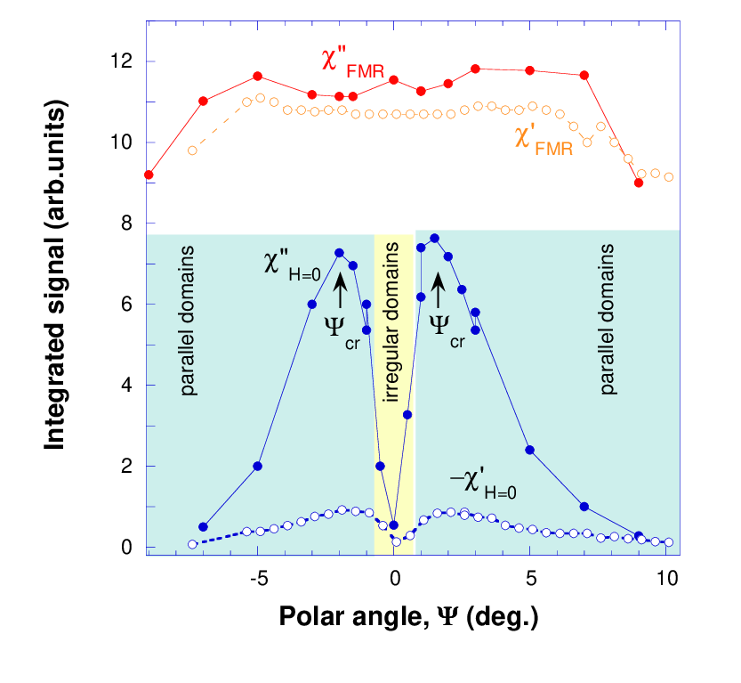

Figure 8 shows the field range where the low-field absorption peak is observed at 295 K. This range has a four-lobed shape with the lobes oriented along the directions . Remarkably, this value coincides with the critical angle that was defined in relation to Eq.5. Indeed, by substituting into Eq.5 the perpendicular anisotropy field, 4 kOe (measured from the FMR in the perpendicular geometry), and the parallel anisotropy field, 180 Oe (found from magnetization measurements) we find . The lobes are within the rectangle defined by the conditions: . The former defines the onset of the multidomain state for the nearly parallel field orientation, while the latter means that the magnetization lies predominantly in-plane (more precisely, the deviation of the magnetization from the in-plane orientation does not exceed ).

III.2.3 Comparison to the model
The unusual angular dependence of the low-field absorption peak (Fig.6) and its hysteretic behavior (Fig.3) imply that the peak magnitude strongly depends on the field orientation during magnetic field sweep. How such dependence on magnetic history can be qualitatively explained by Eqs.11,12? The film has out-of-plane hard axis in the -direction and the in-plane hard axes in the and directions. Figure 8 shows that the low-field absorption appears when the film is in the unsaturated state both with respect to the out-of-plane and in-plane hard axes. This state is presumably the multidomain state. Indeed, there are quite a few observations of magnetic domains in the LSMO films on STO [43, 44, 45, 46, 47, 48]. Photoelectron emission spectroscopy [46] revealed 3-30 m wide parallel domains, magnetic force microscopy showed much smaller, 1 m wide domains [47], or the checkerboard domain pattern with 0.5-0.75 m wide domains [48], and even smaller 0.3 m wide domains (in LCMO thin films) [49]. To explain our results we assume parallel domains whose width and orientation depend on the values of and at the onset of the domain state, hence the dependence on magnetic history.
We attribute the absorption peaks shown in Figs.4, 5 to the tail of the domain mode resonance. The peak magnitude is set by the proximity of the resonant frequency to the operating frequency . Dependence of on magnetic history is captured by the parameter (Eq.13) which is determined by the domain width . The latter is found by minimizing the sum of the energy associated with the stray field of domains and the total energy of domain walls [41]. The onset of the multidomain state is set by while the domain wall energy and, correspondingly, the domain width are set by . The latter can strongly affect the energy and structure of the domain walls and even drive the transition from the Bloch to Néel wall [41, 42]. When the field is lowered, the domain width changes but due to pinning some memory of the magnetic conditions at the onset of the multidomain state is conserved. Since and play very different roles in establishing the domain state, the domain pattern and the frequency of the domain mode resonance (Eq.13) depend on field orientation during field sweep, hence the resulting absorption peak is strongly angular- and field-dependent. We can speak on ”angle-tuned” domain mode resonance.
When the field is parallel to the film, domain width is large and is too low to produce appreciable absorption at 9.4 GHz. When the field is close to the perpendicular orientation, the domain width is small, approaches and absorption strongly increases. When the field is too close to the perpendicular orientation there is no preferential domain wall orientation, domain pattern is irregular, and the resonance is not excited. These considerations can be succinctly summarized as follows: .
III.3 Low-field microwave absorption at low temperatures

Table I demonstrates that the maximum low-field absorption (achieved at different angles for each temperature) does not disappear at low temperatures and even increases. This stays in sharp contrast with the microwave losses associated with magnetoconductance (magnetoresistance), whose magnitude for our highly conducting films dramatically decreases at low temperatures. This proves once again that the low-field microwave absorption is unrelated to magnetoresistance. We observe also that is on the same order as the FMR absorption peak in the parallel geometry. This is not surprising since according to our model the zero-field absorption peak is nothing else but the FMR absorption peak in the parallel geometry which is shifted to zero field due to dynamic demagnetization factor associated with magnetic domains.
| (K) | 11 1 The maximum low-field microwave absorption (at corresponding angle). | 22 2 The magnitude of the FMR absorption peak in parallel field. | 33 3 Nonresonant microwave losses associated with magnetoresistance in parallel field, . |
| 295 | 3.3 | 2.5 | 31 |
| 270 | 3 | 1 | 12 |
| 220 | 2.5 | 3.4 | 6.2 |
| 110 | 4.3 | 4 | 2.8 |
| 4.5 | 8.8 | 2.6 | 0.3 |
The temperature dependence of the low-field absorption is dictated mostly by and its proximity to the operating frequency (Eq.13). The low-field absorption at 295 K arises from the tail of the domain mode resonance since . To estimate at 4.5 K we note that at 4.5 K 7.4 kG (saturation magnetization of LSMO). We substitute this value and 200 nm, and 0.5 m into Eq.13 and find 12.2 GHz, in such a way that . This means that the maximum absorption is achieved at resonant field that satisfies the condition . Upon field sweep across the zero this condition is met twice- once for negative and once for positive field.
Figure 9 shows the low-temperature microwave absorption spectra at different angles. In contrast to Fig.5 there are two low-field absorption peaks: one at negative and one at positive field. There are other differences with respect to Fig.5 as well. The baseline in Fig.9 is flat indicating negligible contribution from magnetoresistance, in such a way that in the parallel orientation the absorption spectrum exhibits only the FMR peak. When the field is rotated away from the parallel orientation there appears a low-field absorption peak that becomes a dominant feature at . This peak disappears again when the deviation from the perpendicular orientation is less than .
IV Conclusions
In thin La0.7Sr0.3MnO3 films with easy-plane anisotropy there is a special kind of the domain mode resonance that is absent in the parallel and perpendicular field orientation and appears only in the oblique magnetic field. It can be ”angle-tuned” by varying the field orientation with respect to the film. The resonance in oblique field should not be unique to manganites and it can be a source of pronounced low-field microwave absorption in other magnetic materials as well.
V Acknowledgments
We are grateful to S. Mercone, S.V. Kapel’nitskii, and K.N. Rozanov for stimulating discussions and constructive comments.
References
- [1] R. C. Haddon, S. H. Glarum, S. V. Chichester, A. P. Ramirez, and N. M. Zimmerman, Phys. Rev. B 43, 2642 (1991).
- [2] B.F. Kim, J. Bohandy, K. Moorjani, and F.J. Adrian, J. Appl. Phys. 63, 2029 (1988).
- [3] F.J. Owens, J. Phys. Chem. Sol. 58, 1311 (1997);ibid. 66, 793 (2005).
- [4] A. I. Veinger, A. G. Zabrodskii, T. V. Tisnek, Supercond. Sci. Technol. 8, 368 (1995).
- [5] G.F. Dionne, IEEE Trans. Magn. 39, 3121 (2003).
- [6] R. Valenzuela, R. Zamorano, G. Alvarez, M.P. Gutierrez, H. Montiel, J. Non-Crystalline Solids 353, 768 (2007).
- [7] H. Montiel, G. Alvarez, R. Zamorano, R. Valenzuela, J. Non-Crystalline Solids 353, 908 (2007)
- [8] D. Stanescu, P. Xavier, J. Richard, and C. Dubourdieu, J. Appl. Phys. 99, 073707 (2006).
- [9] N. Bahlmann, R. Gerhardt, H. Doetsch, J. Magn. Magn. Materials, 16l, 22 (1996).
- [10] V.T. Synogach and H. Dotsch, Phys. Rev. B 54, 15266 (1996).
- [11] N. Vukadinovic, J. Ben Youssef, H. Le Gall, J. Ostorero, Phys.Rev. B. 62, 9021 (2000).
- [12] G.A. Prinz, G.T. Rado, J.J. Krebs, J. Appl. Phys. 53, 2089 (1982).
- [13] F. Gerhardter, Yi Li, K. Baberschke, Phys. Rev. B 47, 11204 (1993).
- [14] S.E. Lofland, V. Ray, P.H. Kim , S.M. Bhagat, K. Ghosh, R.L. Greene, S.G. Karabashev, D.A. Shulyatev, A.A. Arsenov, Y. Mukovskii, J. Phys. Cond. Matter, 9, L633 (1997).
- [15] S. J. Lee, C. C. Tsai, H. Cho, M. Seo, T. Eom, W. Nam, Y. P. Lee,and J. B. Ketterson, J. Appl. Phys. 106, 063922 (2009).
- [16] M. Rivoire and G. Suran, J. Appl. Phys. 78, 1899 (1995).
- [17] J.O. Artman, Phys. Rev. B 105, 74 (1957).
- [18] T.E. Hasty, J. Appl. Phys. 35, 1434 (1964).
- [19] N. M. Salansky, B.P. Khrustalev, Czech. J. Phys. 21, 419 (1971).
- [20] N.A. Buznikov, K.N. Rozanov, J. Magn. Magn. Materials 285, 314 (2005).
- [21] A. Layadi, F. W. Ciarallo, J. 0. Artman, IEEE Trans. Magn., 23, (1987).
- [22] N. Vukadinovic, J. Ben Youssef, H. Le Gall, J. Magn. Magn. Mat. 150, 213 (1995).
- [23] U. Ebels, P.E. Wigen, K. Ounadjela, J.Magn.Magn Materials 177, 1239 (1998).
- [24] S.-Y. Bi, J. Appl. Phys. 67, 3179 (1990).
- [25] O. Acher, C. Boscher, B. Brule, G. Perrin, N. Vukadinovic, G. Suran, H. Joisten, J. Appl. Phys. 81, 4057 (1997).
- [26] A.A. Zakhidov, I.I. Khairullin, V.Y. Sokolov, R.H. Baughman, Z. Iqbal, M. Maxfield, B.L. Ramakrishna, Synthetic Metals 41-43, 3717 (1991).
- [27] J. Dubowik, F. Stobiecki, P.Y. Goscianska, Czech. J. Physics 52, 227 (2002).
- [28] K. Fukui, K. Uno, H. Ohya-Nishiguchi, and H. Kamada, J. Appl. Phys. 83, 2158 (1998).
- [29] J. J. Krebs, P. Lubitz, A. Chaiken, and G. A. Prinz, J.Appl.Phys. 69, 4795 (1991).
- [30] F.J. Rachford, P. Lubitz, C. Vittoria, J. Appl. Phys. 53, 8940 (1982).
- [31] B.A. Belyaev, A.V. Izotov, A.L. Leksikov, IEEE Sensors Journal, 5, 260 (2005).
- [32] V. V. Demidov, I. V. Borisenko, A. A. Klimov, G. A. Ovsyannikov, A. M. Petrzhik, and S. A. Nikitov, J. Exp. Theor. Phys. 112, 825 (2011).
- [33] M.B. Salamon, M. Jaime, Rev. Mod. Phys. 73, 583 (2001).
- [34] S. Budak, M. Ozdemir, B. Aktas, Physica B 339, 45 (2003).
- [35] D. L. Lyfar, S. M. Ryabchenko, V. N. Krivoruchko, S. I. Khartsev, and A. M. Grishin, Phys. Rev. B 69, 100409(R) (2004).
- [36] M. Golosovsky, P. Monod, P. K. Muduli, R. C. Budhani, L. Mechin, and P. Perna, Phys. Rev. B 76, 184414 (2007).
- [37] M.Golosovsky, M.Abu-Teir,D. Davidov, O.Arnache, P.Monod, N.Bontemps, R.C.Budhani, J. Appl. Phys. 98, 084902 (2005).
- [38] D.K. Aswal, A. Singh, R.M. Kadam, M.K. Bhide, A.G. Page, S. Bhattacharya, S.K. Gupta, J.V. Yakhmi, V.C. Sahni, Materials Letters 59, 728 (2005).
- [39] K. Senapati and R. C. Budhani, Phys. Rev. B 71, 224507 (2005).
- [40] F. Yang, L. Mechin, J. M. Routoure, B. Guillet, and R. A. Chakalov, J. Appl. Phys. 99, 024903 (2006).
- [41] A. Hubert, R. Schaefer, Magnetic Domains. The Analysis of Magnetic Microstructures, Springer, Berlin-Heidelberg-New York, 1998. p.238.
- [42] S. A. Manuilov, A. M. Grishin, and M. Munakata, J. Appl. Phys. 109, 083926 (2011).
- [43] P. Lecoeur, Pl. Touilloud, Gang Xiao, A. Gupta, G.Q. Gong, X.W. Li, J. Appl. Phys. 82, 3934 (1997).
- [44] J. Dho, Y. N. Kim, Y. S. Hwang, J. C. Kim, and N. H. Hur, Appl. Phys. Lett. 82, 1434 (2003).
- [45] Y. Murakami, H. Kasai, J. J. Kim, S. Mamishin, D. Shindo, S. Mori, and A. Tonomura, Nature Nanotechnology 5, 37 (2010).
- [46] T. Taniuchi et al. Appl. Phys. Lett. 89, 112505 (2006).
- [47] M. Ziese, Phys. stat. sol. (b) 243, 1383 (2006).
- [48] E. P. Houwman, G. Maris, G. M. De Luca, N. Niermann, G. Rijnders, D. H. A. Blank, and S. Speller, Phys. Rev. B 77, 184412 (2008).
- [49] S. J. Lloyd, N. D. Mathur, J. C. Loudon, and P. A. Midgley, Phys. Rev. B 64, 172407 (2001).